






Показаны все (6)

Фильтр по цене
Фильтровать по брендам

- Национальные инструменты
- PCI ModulesPCI Modules
- Системы PXI
- PXI Шасси
- PXI Контроллер
- Модули PXI
- PXI Semiconductor Test
- PXI FPGA and RIO Modules
- PXI MXI Interfaces
- PXI Programmable Power Supplies & SMU
- PXI Sensor Measurements
- Генераторы сигналов PXI
- PXI Vision
- Сбор данных PXI
- Осциллографы/Цифровые преобразователи PXI
- PXI Счетчики/Таймеры
- PXI РЧ и беспроводное тестирование
- PXI GPIB, Ethernet and VXI
- PXI-коммутаторы
- Цифровые мультиметры PXI
- Цифровой ввод-вывод PXI
- Промышленная связь PXI
- Динамический анализ сигналов PXI
- Передача данных PXI
- CompactDAQ Systems
- CompactRIO Systems
- PCI Modules
- USB Devices
- Устройство программно-определяемого радио USRP
- ключи
- ТекТроникс
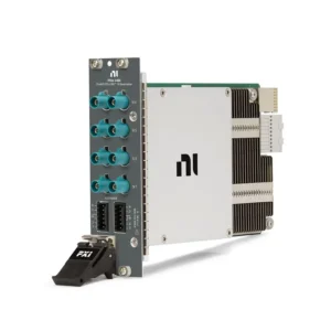
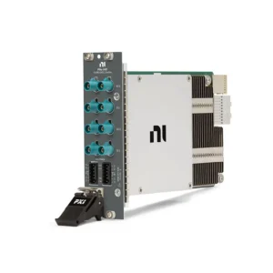
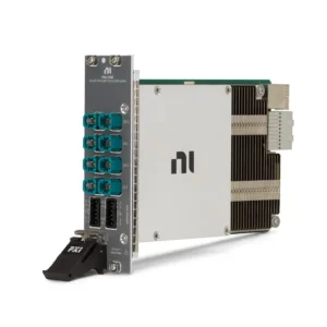
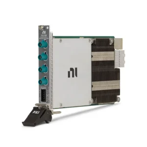
NI PXI Vision and Automotive Camera Interface Modules
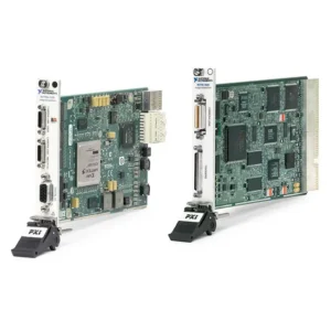
NI PXI Vision modules provide image acquisition, camera simulation, video injection and FPGA-based processing for machine vision, automated optical inspection, automotive camera validation and advanced driver-assistance system testing. They combine PXI Express bandwidth and synchronization with industrial Camera Link, GMSL and FPD-Link interfaces.
Selecting the correct module requires identifying the camera interface, SerDes generation, input or output direction, channel count, video format, pixel rate, trigger requirements and FPGA-processing workload. The chassis, controller, storage path, cable assembly, connector breakout and software environment must also support the total image-data rate.
What Is PXI Vision?
PXI Vision is a modular image acquisition and camera-interface architecture built on the PXI or PXI Express platform. A system can combine camera data with electrical measurements, motion, switching, RF instruments and synchronization hardware under one automated test application.
Traditional machine vision applications acquire images from industrial cameras and analyze them for dimensions, alignment, presence, identification or defects. Automotive vision testing expands this architecture by capturing or generating serialized camera streams used by cameras, electronic control units, displays and ADAS domain controllers.
PXI Vision Interface Types
| Interface Type | Primary Function | Типичные применения | Important Selection Criteria |
|---|---|---|---|
| Camera Link | Acquires images from compatible industrial and scientific cameras | Automated optical inspection, semiconductor inspection, line-scan imaging and scientific research | Base, Medium or Full configuration, pixel clock, tap geometry, PoCL and triggering |
| GMSL2 | Captures or generates serialized automotive camera data | ADAS camera testing, ECU validation, video injection, logging and HIL | Serializer, deserializer, channel direction, video mode, cable and back-channel control |
| GMSL3 | Interfaces with newer high-bandwidth GMSL automotive cameras and ECUs | High-resolution camera validation, autonomous-driving development and next-generation HIL | GMSL generation, Pixel Mode, channel configuration, FPGA image path and ECU compatibility |
| FPD-Link III/IV | Captures or emulates Texas Instruments FPD-Link camera and display connections | Automotive camera, display, ECU and ADAS validation | SerDes device, input/output direction, operating mode, coax or STP connection and power-over-coax |
| GigE Vision | Transfers industrial camera images through Ethernet | Distributed factory inspection and long-distance camera installations | Network bandwidth, camera count, cable distance, packet configuration and triggering |
| USB3 Vision | Connects standardized USB 3 industrial cameras | Laboratory imaging, prototyping and compact inspection systems | Host USB controller bandwidth, cable length, camera power and sustained transfer rate |
GMSL, FPD-Link, Camera Link, GigE Vision and USB3 Vision are different electrical and protocol standards. They are not interchangeable merely because they transfer video. Confirm the camera manufacturer, sensor model, serializer or deserializer, connector, pinout and operating mode before selecting PXI hardware.
NI PXI Vision Module Guide
| Модель | Unique Category | Key Differentiator | Best Fit |
|---|---|---|---|
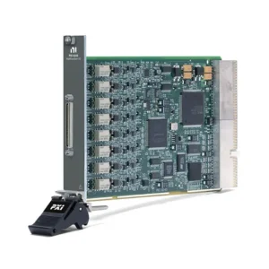
| ПХИ-6143 | Synchronized Electrical Measurement Companion | Eight simultaneously sampled, 16-bit analog inputs at up to 250 kS/s per channel, plus digital I/O and counters; it does not acquire camera images | Correlating camera events with voltage, sensor, encoder or control-system measurements |
| PXIe-1435 | Camera Link Frame Grabber | Supports one Base, Medium or Full Camera Link camera, pixel clocks up to 85 MHz, PoCL, trigger I/O and a quadrature encoder input | Industrial inspection, line-scan imaging, semiconductor inspection and scientific cameras |
| PXIe-1486 | Eight-Channel FPD-Link III Camera Emulator | Eight FPD-Link III outputs using DS90UB953 serializer architecture | Generating simulated automotive camera streams for ECU and ADAS controller testing |
| PXIe-1487 | High-Density GMSL2 FlexRIO Interface | Available in eight-input, eight-output or four-input/four-output configurations with a user-programmable FPGA | GMSL2 camera capture, playback, ECU video injection, data logging and HIL validation |
| PXIe-1488 | High-Density FPD-Link III/IV FlexRIO Interface | Configurable input, output or bidirectional FPD-Link architecture with a Kintex UltraScale+ FPGA and onboard DRAM | Automotive camera, display and ECU testing using FPD-Link III or IV |
| PXIe-1489 | Four-Channel GMSL3 FlexRIO Interface | Available with four inputs, four outputs or two inputs and two outputs, with GMSL3 Pixel Mode and a Kintex UltraScale+ FPGA | Next-generation high-bandwidth automotive camera and ADAS validation |
The PXI-6143 is a simultaneous-sampling DAQ module rather than a frame grabber or automotive SerDes interface. It can complement a vision system when electrical signals must be measured at the same time as an image event, but it cannot replace the PXIe-1435 or PXIe-148x camera-interface modules.
How to Select a PXI Vision Module
1. Identify the Exact Camera Interface
Begin with the camera, ECU or display datasheet. Determine whether the interface is Camera Link, GMSL2, GMSL3, FPD-Link III, FPD-Link IV, GigE Vision, USB3 Vision or another protocol.
For an automotive SerDes interface, record the serializer and deserializer part numbers. Equipment using different GMSL or FPD-Link generations may share a similar connector while remaining electrically or logically incompatible.
2. Determine Capture or Generation Direction
An input configuration receives video from a camera or ECU output and normally uses deserializer hardware. An output configuration generates a camera-like or display-like stream and normally uses serializer hardware.
A bidirectional configuration combines inputs and outputs for capture-and-playback, pass-through processing or closed-loop HIL testing. The channel direction is determined by the ordered hardware variant and generally cannot be changed only through software.
| Test Requirement | Required Direction | Typical Hardware Role |
|---|---|---|
| Capture images from an automotive camera | Input | Deserializer receives the serialized camera stream |
| Inject prerecorded video into an ECU | Output | Serializer emulates the camera connection |
| Record and later reproduce camera data | Input and output | Capture, storage and playback data paths |
| Modify video before sending it to the ECU | Двунаправленный | Deserializer, FPGA processing and serializer |
| Test an automotive display or display controller | Application dependent | Confirm whether the DUT sources or receives the video stream |
3. Select the Required Channel Count
Count every physical camera or video link that must operate simultaneously. The PXIe-1487 and PXIe-1488 provide high-density configurations for systems requiring up to eight input or output links, while the PXIe-1489 provides four GMSL3 channels.
Do not assume that an eight-channel model provides eight inputs and eight outputs simultaneously. Verify the specific part number because input-only, output-only and mixed-direction versions use different onboard SerDes devices.
4. Calculate Image-Data Throughput
Estimate the uncompressed image rate before selecting the PXIe chassis, controller and storage system:
Image data rate = width × height × frame rate × transferred bits per pixel × active streams.
Include image blanking, protocol overhead, metadata, embedded data, multiple exposures and simultaneous playback streams where applicable. Packed RAW10, RAW12 and RAW14 formats may be transferred or stored differently from their nominal pixel depth.
The camera link rate is not automatically equal to the disk-write rate. FPGA preprocessing, pixel unpacking, image conversion and file formatting can increase or reduce the data transferred to host memory.
5. Verify Resolution, Frame Rate and Video Format
Confirm the maximum resolution, frames per second, pixel clock, number of lanes, pixel format and virtual-channel configuration. Automotive cameras may use raw Bayer data, YUV, RGB, embedded metadata or multiple virtual channels within one serialized link.
The interface generation alone does not guarantee support for every camera format. The FPGA image path, SerDes mode and available example design must understand the stream produced by the camera or required by the ECU.
6. Review FPGA Processing Requirements
FlexRIO-based automotive interfaces expose a user-programmable FPGA for functions such as video routing, format conversion, region-of-interest extraction, metadata handling, fault insertion and low-latency processing.
Check whether the application can use a supplied example design or requires custom LabVIEW FPGA development. Custom processing also consumes FPGA logic, memory, DMA channels and development time.
7. Verify Triggering and Synchronization
Machine vision systems may need to synchronize camera exposure with a strobe, conveyor encoder, motion stage or electrical measurement. The PXIe-1435 includes industrial trigger I/O and a quadrature encoder input for compatible Camera Link systems.
Automotive vision tests may need to coordinate video playback with CAN, Automotive Ethernet, power, RF or sensor-simulation events. PXI timing resources can distribute triggers between modules, but camera-frame alignment and protocol timing still require application-specific configuration.
8. Confirm Cable, Connector and Power Requirements
Verify the complete signal path, including the camera connector, coax or shielded twisted-pair cable, breakout assembly, SerDes pinout, power-over-coax requirement and control-channel wiring.
Automotive cameras frequently combine video, power and bidirectional control on the same physical cable. Incorrect voltage, polarity or PoC configuration can damage the camera, interface module or DUT.
9. Select the PXIe Chassis and Controller
High-resolution multichannel vision applications require substantial PCI Express, memory and storage bandwidth. Review the selected Шасси PXI slot map, PCIe generation, lane width, segment bandwidth, cooling and controller connection.
Земля PXI controller must provide sufficient processing, system memory and PCIe throughput for acquisition, analysis, display and recording. A compatible external workstation may be used when greater CPU, GPU or storage expansion is required.
Camera Link Machine Vision Systems
Camera Link is designed for deterministic, high-throughput image transfer from industrial and scientific cameras. The PXIe-1435 supports Base, Medium and Full Camera Link configurations, pixel clocks from 20 MHz to 85 MHz and image widths up to 80 bits.
Power over Camera Link can supply a compatible camera through the camera cable, reducing external wiring. Before enabling PoCL, verify the camera, cable and power requirements. Camera Link serial communication can be used to configure exposure, gain, tap arrangement and operating mode.
For line-scan and web-inspection systems, an encoder can trigger image lines according to material movement. This produces more consistent spatial sampling than triggering only at a fixed time interval when conveyor speed changes.
Automotive Camera Capture and Video Injection
Camera Capture
Camera capture receives the serialized output from a physical automotive camera. The interface deserializes the stream, transfers image data through the FPGA and sends selected data to host memory or storage.
Capture systems are used for camera characterization, production testing, image-quality analysis, in-vehicle logging and recording data for later reproduction.
Camera Emulation and Video Injection
Camera emulation generates a serialized stream expected by an ECU or ADAS controller. The source may be a prerecorded camera sequence, synthetic scene, modified image or algorithmically generated test pattern.
Video injection allows the test system to reproduce repeatable driving scenarios without requiring a physical camera and scene for every test. Timing, metadata, virtual channels, frame counters and control-channel behavior must match the receiving ECU.
Pass-Through and Fault Insertion
A mixed input/output interface can receive a camera stream, process it in the FPGA and transmit the modified stream to the ECU. This architecture supports image manipulation, delay insertion, frozen frames, dropped frames, corrupted metadata and other controlled fault conditions.
Safety-related testing should validate that the selected module and FPGA design can introduce the required fault without unintentionally changing unrelated portions of the stream.
GMSL and FPD-Link Selection
| Consideration | GMSL | FPD-Link |
|---|---|---|
| Primary Supplier Ecosystem | Analog Devices/Maxim Integrated serializer and deserializer families | Texas Instruments serializer and deserializer families |
| Typical Application | Automotive cameras, ECUs and high-speed vehicle video links | Automotive cameras, displays, ECUs and video distribution |
| Current PXI Models | PXIe-1487 for GMSL2 and PXIe-1489 for GMSL3 | PXIe-1486 for FPD-Link III output and PXIe-1488 for configurable FPD-Link III/IV testing |
| Compatibility Requirement | Match GMSL generation, SerDes device, mode and control channel | Match FPD-Link generation, SerDes device, mode and control channel |
| Interchangeability | GMSL and FPD-Link hardware are not directly interchangeable | |
PXI Vision Software
NI Vision Acquisition Software provides camera discovery, configuration and acquisition support for compatible frame grabbers and camera interfaces. NI Measurement & Automation Explorer can be used to detect supported hardware and test compatible acquisition configurations.
The Vision Development Module provides image-processing and machine-vision functions such as filtering, pattern matching, edge detection, particle analysis, measurement and identification. It is separate from the hardware driver and should be included only when the application requires those analysis functions.
PXI FlexRIO automotive interfaces may also require the FlexRIO driver, LabVIEW FPGA Module, compatible example projects and model-specific firmware or FPGA images. Confirm software versions before ordering replacement or additional modules for an existing system.
Image Storage and Data Streaming
Raw multichannel camera data can consume storage rapidly. Determine whether the application will process images in real time, retain selected frames, record every stream or replay previously captured data.
Continuous recording requires a validated path from the camera interface through the PXIe backplane and controller memory to the storage target. Review PXI data-streaming solutions when sustained recording or playback is required.
Benchmark the final configuration with the intended resolution, frame rate, channel count, pixel format, file structure and recording duration. Short storage benchmarks may not reveal thermal throttling, buffer overflow or sustained-write limitations.
Typical PXI Vision Applications
- Automated optical inspection and defect detection
- Semiconductor wafer and component inspection
- PCB assembly and solder-joint inspection
- Line-scan, web and conveyor inspection
- Scientific, microscopy and laboratory imaging
- ADAS camera characterization and validation
- Automotive ECU video injection
- Camera simulation and prerecorded video playback
- GMSL and FPD-Link interface validation
- Automotive hardware-in-the-loop testing
- In-vehicle camera-data logging
- Robot guidance and motion-synchronized imaging
- Display and infotainment video-interface testing
- Combined optical and electrical production test
Legacy Vision System Replacement
Replacing a legacy frame grabber or automotive camera interface requires checking more than the PXI form factor. Newer hardware may use a different camera standard, connector, SerDes device, FPGA architecture, driver or software API.
Compare the following before approving a replacement:
- PXI or PXI Express slot compatibility
- Camera interface and protocol generation
- Serializer and deserializer part numbers
- Input, output or mixed channel direction
- Number of simultaneous video links
- Resolution, frame rate and pixel format
- Camera trigger, encoder and digital I/O requirements
- Cable, connector, breakout and pinout
- Power-over-coax or Power over Camera Link requirements
- FPGA code and example-project compatibility
- Driver, LabVIEW and operating-system support
- Chassis bandwidth, cooling and storage throughput
A module with greater bandwidth may still require new cables, FPGA development, software changes and complete system requalification.
PXI Vision Procurement and RFQ Guide
Provide the following information for technical review and quotation:
- Camera, ECU or display manufacturer and complete model
- Required PXI Vision module and part number
- Camera Link, GMSL or FPD-Link generation
- Serializer and deserializer part numbers
- Required input and output channel configuration
- Image resolution, frame rate and pixel format
- Video mode and virtual-channel requirements
- Camera connector, cable type and required length
- Power-over-coax or PoCL requirements
- Trigger, synchronization and encoder requirements
- Required FPGA processing or fault insertion
- Continuous recording and playback data rates
- Existing PXIe chassis and controller models
- Operating system and NI software versions
- Required quantity and preferred product condition
For pre-owned vision hardware, request module-recognition results, interface testing and inspection of the camera, cable and backplane connectors. Detection by the PXI controller alone does not verify image acquisition, video generation or SerDes link operation.
Часто задаваемые вопросы
Is the PXI-6143 a PXI Vision frame grabber?
No. The PXI-6143 is an eight-channel simultaneous-sampling analog input module. It can measure electrical signals alongside a vision test, but it does not connect to or acquire images from a camera.
What is the difference between PXIe-1435 and PXIe-1487?
The PXIe-1435 is a Camera Link frame grabber for industrial and scientific cameras. The PXIe-1487 is a FlexRIO GMSL interface for automotive camera capture, emulation and ADAS testing. The camera standards and intended applications are different.
Can a GMSL interface test an FPD-Link camera?
No. GMSL and FPD-Link use different SerDes technologies. Select a module that matches the camera or ECU interface, protocol generation and serializer or deserializer device.
What is the difference between PXIe-1487 and PXIe-1489?
The PXIe-1487 supports high-density GMSL2 configurations with up to eight links. The PXIe-1489 provides four GMSL3 links for newer high-bandwidth automotive camera systems.
Can an input module generate camera video?
Not unless the ordered hardware includes output serializer channels. Input, output and mixed-direction configurations contain different SerDes components, so the required direction must be selected before ordering.
Is Vision Acquisition Software the same as Vision Development Module?
No. Vision Acquisition Software provides camera and image-acquisition drivers. Vision Development Module adds image-processing and machine-vision analysis functions. FlexRIO automotive interfaces may also require LabVIEW FPGA and model-specific examples.
How is a camera synchronized with electrical measurements?
Use compatible trigger lines, PXI timing resources or synchronization modules to coordinate image exposure with DAQ, motion or other instruments. Timestamping alone does not always provide deterministic exposure alignment.
Can PXI Vision continuously record every camera stream?
Only when the complete PXIe backplane, controller memory, software buffers and storage target sustain the aggregate data rate. Validate the final system under the intended channel count and recording duration.
Recommended PXI Vision Modules
Consider the PXIe-1435 for Camera Link machine vision, the PXIe-1487 for high-density GMSL2 testing, the PXIe-1488 for configurable FPD-Link III/IV systems, or the PXIe-1489 for four-channel GMSL3 camera and ECU validation.
Related NI PXI Solutions
Explore PXI FPGA and RIO modules for custom real-time processing, PXI data acquisition modules for synchronized electrical measurements, or the complete NI PXI system catalog for compatible chassis, controllers and instruments.
NI PXI Vision Solutions from PXISOURCE
PXISOURCE supports engineers, automotive validation teams, system integrators and procurement departments with camera-interface identification, SerDes compatibility review, PXI module selection, chassis and controller matching, legacy-system replacement and sourcing for new or existing vision platforms.
Need help selecting an NI PXI Vision module? Email sales@pxisource.com or contact PXISOURCE through WhatsApp.