




- Национальные инструменты
- Системы PXI
- PXI Шасси
- PXI Контроллер
- Модули PXI
- PXI Semiconductor Test
- PXI FPGA and RIO Modules
- PXI MXI Interfaces
- PXI Programmable Power Supplies & SMU
- PXI Sensor Measurements
- Генераторы сигналов PXI
- PXI Vision
- Сбор данных PXI
- Осциллографы/Цифровые преобразователи PXI
- PXI Счетчики/Таймеры
- PXI РЧ и беспроводное тестирование
- PXI GPIB, Ethernet and VXI
- PXI-коммутаторы
- Цифровые мультиметры PXI
- Цифровой ввод-вывод PXI
- Промышленная связь PXI
- Динамический анализ сигналов PXI
- Передача данных PXI
- CompactDAQ Systems
- CompactRIO Systems
- PCI Modules
- USB Devices
- Устройство программно-определяемого радио USRP
- Системы PXI
- ключи
- ТекТроникс
C Series Digital Input Module
Товаров, соответствующих вашему запросу, не обнаружено.
NI C Series Digital Input Modules
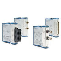
NI C Series Digital Input Modules acquire logic states, switch signals, industrial sensors, relay contacts and digital control signals in compatible CompactDAQ and CompactRIO systems. They are used for machine monitoring, production test, safety-status monitoring, position sensing, automotive validation and embedded control applications.
The correct module depends on the electrical signal rather than the number of digital points alone. TTL, differential, sinking, sourcing and 24 V industrial signals require different input architectures, thresholds, isolation levels and wiring arrangements.
What Is a C Series Digital Input Module?
A C Series digital input module detects whether an external signal is in a logical high or low state. It converts field-level signals into data that can be monitored, logged, synchronized with analog measurements or used by an embedded control application.
Digital input modules can support logic-level signals, industrial-voltage signals, differential digital signals and isolated field I/O. The input type determines how sensors, switches, encoders, PLC outputs, relays and other equipment must be wired.
Do not connect a 24 V industrial signal to a TTL-level digital input module. Confirm the external signal voltage, polarity, sourcing or sinking behavior, common reference, isolation requirement and maximum transient conditions before wiring the module.
C Series Digital Input Types
| Input Type | Typical External Signal | Key Selection Factors | Типичные применения |
|---|---|---|---|
| TTL and Logic-Level Input | 5 V or other compatible logic-level digital signals | Logic threshold, update rate, line direction, reference and connector type | Electronic test, laboratory systems, digital fixtures and logic monitoring |
| High-Speed Digital Input | Rapid state changes, pulse trains and digital events | Maximum rate, timing engine, buffering, synchronization and cable quality | Pulse monitoring, fast digital test, motion feedback and event capture |
| Differential Digital Input | Balanced differential logic signals | Supported differential standard, line termination, cable impedance and noise environment | Longer cable runs, noise-sensitive digital systems and differential encoders |
| Industrial Voltage Digital Input | 24 V field sensors, PLC outputs, relay contacts and industrial control signals | Input voltage range, source type, input current, isolation and external field power | Factory automation, machinery, process systems and sensor-status monitoring |
| Isolated Digital Input | Field digital signals with ground-potential differences | Isolation topology, common-mode limits, bank grouping and field wiring | Distributed equipment, industrial cabinets and electrically noisy installations |
Representative NI C Series Digital Input Modules
| Модель | Unique Category | Key Differentiator | Best Fit |
|---|---|---|---|
| NI-9401 | High-Speed TTL Digital I/O | Fast logic-level digital interface with bidirectional operation | Digital test, pulse monitoring, custom timing and embedded control systems |
| NI-9411 | Differential Digital Input | Differential digital input architecture for compatible high-speed signals | Noise-sensitive digital monitoring and differential signal acquisition |
| NI-9412 | Differential Digital Input | Multichannel differential digital signal monitoring | Encoder-related signals, industrial digital feedback and differential I/O systems |
| NI-9421 | Industrial Digital Input | Field-level digital input for industrial control signals | PLC status monitoring, switches, sensors and machine-state acquisition |
| NI-9423 | Industrial Digital Input | Industrial digital input architecture for field wiring applications | Factory automation, relay contacts and industrial sensor interfaces |
| NI-9425 | High-Density Industrial Digital Input | High channel density for large industrial digital input systems | Production fixtures, machine monitoring and multichannel status acquisition |
This table represents common C Series digital input architectures rather than every available module. Confirm the exact module model, input voltage, wiring type, isolation arrangement, terminal accessory and software support before ordering.
How to Choose a C Series Digital Input Module
1. Identify the Signal Voltage and Logic Standard
Start with the output specification of the external device. Determine whether it provides TTL logic, differential logic, 24 V industrial output, relay contact closure, open collector, push-pull output or another digital interface.
Record the nominal and maximum voltage, logic threshold, signal polarity, source type, common reference and expected switching rate. These values define the required input architecture.
2. Determine Sourcing or Sinking Behavior
Industrial digital systems commonly use sourcing and sinking terminology. A sourcing device provides positive voltage to the input, while a sinking device provides a path to the return reference. The module, external sensor and field power supply must be wired as a compatible system.
Do not assume that a module can accept both sourcing and sinking signals without checking its wiring diagram. Incorrect polarity or reference wiring can prevent detection or damage the connected equipment.
3. Select the Required Channel Count
Count the monitored signals, including limit switches, fault outputs, relay contacts, interlocks, proximity sensors, device-ready signals and spare channels. Include future expansion where the equipment design is expected to grow.
High-density modules can reduce chassis space and wiring complexity, while lower-channel-count modules can be easier to isolate, troubleshoot and group by machine function.
4. Determine Required Update Rate
Slow machine status signals may only need periodic software polling. Fast pulses, encoder signals, short events and rapidly changing logic require a module and timing architecture capable of detecting transitions at the required rate.
A standard sampled digital input is not automatically a replacement for a counter, timer or dedicated encoder interface. For edge counting, frequency, position or pulse-width measurement, evaluate a compatible counter module or FPGA-based implementation.
5. Review Isolation and Grounding
Industrial equipment can have ground-potential differences, switching noise and transients that are not present in laboratory logic circuits. Isolation can protect the measurement platform and reduce ground-loop problems, but the isolation topology must match the actual field wiring.
Check whether channels are isolated individually, in banks or not isolated. Also review shield termination, cabinet grounding, cable routing and nearby contactors, motors or variable-frequency drives.
6. Confirm Connector and Field Wiring
Digital input modules can use different terminal blocks, connectors and pin assignments. Confirm the module connector, mating accessory, terminal labeling, external power routing and fuse or protection requirements before installation.
Use suitable cable type, wire gauge and strain relief for the installation. Long unshielded cables placed near high-current switching equipment can introduce false transitions or unreliable status readings.
TTL and Logic-Level Digital Inputs
Logic-level digital input modules are used for electronic circuits, test fixtures, laboratory instruments and embedded devices. They are designed for compatible low-voltage logic levels and are not intended to accept industrial field voltage directly.
Important selection factors include input threshold, logic family compatibility, maximum switching rate, cable length, common reference, line direction and whether the application also requires digital output capability.
For fast logic signals, use controlled cable routing and confirm whether the system requires termination, differential signaling, edge capture or FPGA-based timing.
Industrial 24 V Digital Inputs
Industrial digital input modules are used with field sensors, PLC outputs, relays, contact closures and machine-control signals. They are designed for higher-voltage field wiring and can provide isolation or more robust input conditioning than logic-level modules.
Before connecting a field signal, confirm:
- Nominal and maximum input voltage
- Sourcing, sinking or push-pull external device output
- Required field power supply and return reference
- Input current and load requirements
- Isolation topology and common-mode conditions
- Switching speed, pulse width and debounce requirements
- Surge protection, fusing and cabinet-wiring practices
Digital Timing, Counters and FPGA Processing
Digital input modules report logic states, but many applications also need accurate timing information. Examples include encoder position, pulse frequency, pulse width, edge count and precise event timestamps.
For those requirements, verify whether the selected module and platform provide suitable hardware timing. CompactRIO systems can use FPGA logic for custom edge detection, pulse processing and deterministic response. For standard counter functions, review compatible counter and timer hardware instead of relying on a software loop.
CompactDAQ and CompactRIO Compatibility
C Series digital input modules can be used in compatible CompactDAQ systems и CompactRIO systems. The selected platform affects timing, software support, synchronization and embedded deployment options.
CompactDAQ is suitable for PC-based digital monitoring, test fixtures and data logging. CompactRIO is appropriate when the application requires deterministic response, custom FPGA logic, high-speed event handling or embedded machine control.
Software and Synchronization
CompactDAQ digital input systems commonly use NI-DAQmx for device configuration, data acquisition, timing and triggering. CompactRIO systems can use NI-RIO, LabVIEW Real-Time and LabVIEW FPGA for embedded control and custom I/O processing.
For systems that combine digital and analog signals, define the clock, trigger and timestamp relationship before development. Software polling alone is not sufficient when precise correlation between a digital event and an analog waveform is required.
Типичные применения
- Machine state, alarm and interlock monitoring
- PLC and industrial sensor signal acquisition
- Limit switch, relay contact and proximity sensor monitoring
- Automated production and functional test fixtures
- Digital logic verification and electronic-device validation
- Automotive, aerospace and transportation test systems
- Encoder, pulse and event monitoring with suitable timing hardware
- Hardware-in-the-loop and embedded control systems
- Energy, battery and power-electronics status monitoring
- Distributed industrial I/O and condition-monitoring systems
C Series Digital Input Module Procurement Guide
Provide the following information for accurate module selection and quotation:
- External device manufacturer and complete model
- Digital signal type: TTL, differential, 24 V, relay contact or other interface
- Nominal voltage, maximum voltage and logic threshold
- Sourcing, sinking, push-pull or open-collector output behavior
- Required channel quantity and future expansion needs
- Required switching rate, event timing or pulse-width requirement
- Isolation, grounding, cable length and field-power conditions
- Required terminal block, connector and field-wiring accessory
- Existing CompactDAQ chassis or CompactRIO controller model
- Required synchronization with analog, counter or output signals
- Operating system, driver and software version
- New or pre-owned hardware preference
Часто задаваемые вопросы
Can a 24 V sensor be connected to a TTL digital input module?
No. A 24 V industrial signal can exceed the limits of a TTL input. Use a compatible industrial digital input module or an approved external signal-conditioning interface.
What is the difference between sourcing and sinking digital signals?
A sourcing output supplies positive voltage to the connected input, while a sinking output provides a path to the return reference. The external device, module wiring and field power supply must be configured as a compatible circuit.
Do I need isolation for digital input signals?
Isolation is especially valuable when signals originate from distributed machinery, separate power systems or electrically noisy industrial equipment. The required isolation level depends on the grounding and common-mode conditions of the actual installation.
Can a digital input module measure encoder position?
Not always. Simple digital inputs can detect states, but accurate encoder position or pulse-frequency measurement generally requires compatible counter hardware, an encoder-capable module or FPGA-based processing.
Can digital input and analog input channels be synchronized?
Yes, when the selected platform, modules and timing architecture support shared clocks or triggers. Confirm the complete synchronization design when event timing must be correlated with analog measurements.
Can C Series digital input modules be used with CompactRIO?
Yes, when the exact module is supported by the selected CompactRIO controller or chassis. CompactRIO is useful for deterministic digital control, custom FPGA timing and embedded I/O processing.
Related NI C Series Solutions
Explore the complete NI C Series module range for analog, digital output, temperature and communication I/O. Pair digital input modules with a compatible CompactDAQ chassis for PC-based monitoring, or a CompactRIO controller for embedded real-time and FPGA applications.
NI C Series Digital Input Modules from PXISOURCE
PXISOURCE supports engineers, system integrators and procurement teams with digital interface identification, C Series module selection, CompactDAQ and CompactRIO compatibility review, field-wiring accessory matching and legacy-module replacement. Send the external-device datasheet, signal voltage, channel count, switching-rate requirement, platform model and preferred hardware condition for a technically matched quotation.
Need help selecting an NI C Series digital input module? Email sales@pxisource.com or contact PXISOURCE on WhatsApp.