




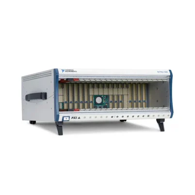
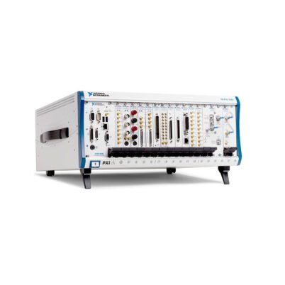

PXIe-1075 18-Slot PXI Express Chassis
Земля NI PXIe-1075 is a high-density 18-slot PXI Express chassis designed for automated test, high-channel-count data acquisition, electronic validation, RF testing and hardware-in-the-loop systems. It combines a system controller position, a dedicated system timing slot and 16 additional peripheral positions in a full-width modular enclosure.
The peripheral architecture includes eight PXI hybrid slots, eight PXI Express slots and one PXI Express system timing slot. This combination supports modern PXI Express instruments while maintaining compatibility with conventional PXI modules that have hybrid-compatible connectors.
With up to 4 GB/s aggregate system bandwidth, 791 W of usable DC power, 38.25 W cooling capacity per peripheral slot and advanced timing connections, the PXIe-1075 provides a scalable platform for synchronized automated test and measurement systems.
Key Features of the PXIe-1075
- PXI Express шасси на 18 слотов
- One system controller slot
- 17 peripheral instrument positions
- Eight PXI hybrid peripheral slots
- Eight PXI Express peripheral slots
- One PXI Express system timing slot
- Up to 4 GB/s aggregate system bandwidth
- Compatible with embedded and remote controllers
- 791 W maximum usable DC power
- 140 W maximum controller dissipation
- 38.25 W cooling capacity per peripheral slot
- Three 165 CFM module-cooling fans
- Automatic and High fan-speed settings
- External 10 MHz reference-clock input and output
- PXI star trigger support
- PXI Express differential star trigger support
- Rear-panel remote power-control connector
- Replaceable power-supply shuttle
- 0°C to 55°C operating-temperature range
- Rack-mountable full-width design
18-Slot High-Density Architecture
The PXIe-1075 provides 18 functional chassis positions. One position is assigned to the system controller, while 17 positions are available for timing and peripheral instruments.
The system controller slot includes three expansion positions required by compatible multi-slot embedded controllers and remote-control modules. These expansion positions form part of the controller area and are not counted as separate peripheral instrument slots.
The large peripheral capacity allows one chassis to integrate digitizers, digital multimeters, waveform generators, source measure units, switch modules, data acquisition devices, RF instruments and communication interfaces.
Eight PXI Hybrid Slots
Eight peripheral positions use PXI hybrid connectors. These positions accept PXI Express modules and compatible conventional PXI or CompactPCI instruments.
The hybrid architecture helps organizations preserve investments in existing PXI hardware while adding newer PXI Express instrumentation. Conventional switches, DAQ modules and communication interfaces can operate alongside newer digitizers, RF devices and FPGA instruments.
Some early PXI modules use rear connectors that are not physically compatible with hybrid slots. Always check the module connector arrangement and documentation before installation.
Eight PXI Express Slots
Eight standard peripheral positions are intended for PXI Express modules. These slots provide PCI Express-based communication between the installed instruments and the system controller.
PXI Express positions can accommodate high-speed digitizers, waveform generators, digital instruments, RF modules and other PCI Express-based measurement devices, provided their power and cooling requirements remain within specification.
Conventional PXI modules should be installed only in compatible hybrid positions because PXI Express-only slots do not provide the parallel PCI bus connections required by traditional PXI instruments.
PXI Express System Timing Slot
The dedicated system timing slot provides access to the chassis’s timing and synchronization resources. A compatible timing module can distribute or discipline reference clocks, route triggers and synchronize the chassis with other measurement systems.
The timing position supports access to PXI star triggers, PXI Express differential star triggers, PXIe_SYNC_CTRL and the system reference-clock architecture.
When no dedicated timing module is required, the system timing position can support a compatible PXI Express peripheral module, subject to the module documentation and chassis configuration.
4 GB/s System Bandwidth
The PXIe-1075 provides up to 4 GB/s of aggregate system bandwidth. This supports multichannel data acquisition, RF measurement, moderate-speed waveform streaming and automated test systems using several simultaneous instruments.
System bandwidth is shared across the chassis architecture. The actual throughput available to an individual module depends on its slot, controller, PCI Express link and the activity of other instruments.
Applications involving multiple newer-generation digitizers, vector signal transceivers or FlexRIO modules may require more than 4 GB/s. In those cases, a 12 GB/s or 24 GB/s chassis should be considered.
Embedded and Remote Controller Support
A PXI Express embedded controller can be installed directly in the system slot to create a self-contained test platform. The embedded controller provides the processor, memory, storage, network interfaces and operating system.
The system slot can alternatively accommodate a compatible remote-control module. This configuration connects the PXIe-1075 to an external desktop computer, workstation or server through the corresponding host interface and cable.
Controller selection should consider processing performance, physical width, power consumption, operating-system support, interface bandwidth and required long-term availability.
PXIe-1075 Technical Specifications
| Product Model | PXIe-1075 |
|---|---|
| Common Part Number | 780149-01 |
| Product Type | High-density PXI Express chassis |
| Total Functional Slots | 18 |
| System Controller Slots | 1 system slot with 3 system expansion positions |
| Total Peripheral Positions | 17 |
| PXI Hybrid Peripheral Slots | 8 |
| PXI Express Peripheral Slots | 8 |
| PXI Express System Timing Slots | 1 |
| Maximum System Bandwidth | Up to 4 GB/s |
| Maximum Usable DC Power | 791 W |
| Maximum Controller Dissipation | 140 W |
| Maximum Peripheral-Slot Dissipation | 38.25 W per slot |
| Module Cooling | 3 × 165 CFM forced-air fans |
| Fan Modes | Auto and High |
| Slot Airflow Direction | Bottom of module to top of module |
| AC Input Voltage | 100–120 VAC or 220–240 VAC |
| Operating Voltage Range | 90–120 VAC or 200–264 VAC |
| Input Current Rating | 12 A at low-line input or 6 A at high-line input |
| Input Frequency | 50/60 Hz |
| Operating Frequency Range | 47–63 Hz |
| AC Overcurrent Protection | 15 A circuit breaker |
| Typical Power-Supply Efficiency | 70% |
| Power-Supply Replacement Time | Under 5 minutes specified MTTR |
| PXI_CLK10 Accuracy | ±25 ppm maximum |
| PXI_CLK10 Slot-to-Slot Skew | 500 ps maximum |
| PXIe_CLK100 Slot-to-Slot Skew | 100 ps maximum |
| External Reference Input | 10 MHz through rear-panel BNC or timing-slot PXI_CLK10_IN |
| External Reference Output | 10 MHz through rear-panel BNC |
| Operating Temperature | 0°C to 55°C |
| Operating Humidity | 10% to 90%, noncondensing |
| Storage Temperature | -40°C to 71°C |
| Storage Humidity | 5% to 95%, noncondensing |
| Maximum Operating Altitude | 2,000 m at 25°C ambient temperature |
| Operational Shock | 30 g peak, half-sine, 11 ms pulse |
| Operating Random Vibration | 5–500 Hz, 0.3 grms |
| Auto-Fan Sound Pressure | 45.0 dBA at up to approximately 30°C ambient |
| High-Fan Sound Pressure | 63.3 dBA |
| Dimensions | 177.1 × 464.8 × 467.4 mm |
| Dimensions in Inches | 6.97 × 18.30 × 18.40 in. |
| Weight | 14.06 kg |
| Intended Environment | Indoor use only |
791 W Usable DC Power
The PXIe-1075 provides a maximum of 791 W of usable DC output power. This high total capacity supports a system controller and a large collection of peripheral instruments.
Power consumption must be checked both as a total and by individual voltage rail. A configuration can remain below 791 W while exceeding the current available from one rail.
| DC Rail | Максимальный ток |
|---|---|
| +3.3 V | 60 A |
| +5 V | 48 A |
| +12 V | 62 A |
| -12 V | 4 A |
| +5 V Auxiliary | 2 A |
The system controller position should not draw more than 45 A total and must not dissipate more than 140 W. Each peripheral position is limited by its applicable slot-current and 38.25 W dissipation ratings.
Power-Supply Protection
All DC outputs include short-circuit and overload protection with automatic recovery. The +3.3 V and +5 V outputs include overvoltage protection clamped approximately 20% to 30% above their nominal voltages.
Protection circuitry helps limit damage during an abnormal condition, but it does not replace correct power-budget calculations or proper system installation.
If the chassis repeatedly shuts down, disconnect AC power and test the configuration with peripheral modules removed. Reinstall the modules individually to identify an overloaded rail or faulty instrument.
Replaceable Power-Supply Shuttle
The chassis uses a serviceable power-supply shuttle. NI specifies a mean time to repair of less than five minutes for power-supply shuttle replacement when the correct procedure and replacement assembly are used.
This service-oriented design can reduce downtime in production and validation systems where the chassis must be returned to operation quickly.
Disconnect the AC cable before servicing the chassis. Power-supply replacement should be performed only by qualified personnel following the applicable service instructions.
Three 165 CFM Cooling Fans
The PXIe-1075 uses three 165 CFM fans to provide positive-pressure cooling for the controller and peripheral modules.
Cooling air enters through the bottom-rear area, passes from the bottom to the top of the installed modules and exits along both sides and the top of the chassis.
The power supply has a separate integrated fan with right-side intake and left-side exhaust. Maintain approximately 44.45 mm of clearance around the top and side vents and at least 76.2 mm behind the chassis.
38.25 W Cooling per Peripheral Slot
Each peripheral position supports a maximum module dissipation of 38.25 W. This rating is appropriate for many DAQ modules, digitizers, switches, communication interfaces and RF instruments produced for earlier PXI Express generations.
Total available chassis power does not override the cooling limit of an individual slot. A module requiring more than 38.25 W of cooling should not be installed even if sufficient total power remains.
Use filler panels in unused positions to direct airflow through populated slots and prevent hot-air recirculation.
Fan Filters and Maintenance
The chassis includes 30 ppi polyurethane foam fan-filter material. NI specifies a maximum fan-filter cleaning interval of six months.
The correct maintenance interval can be shorter in dusty production facilities, workshops or laboratories. Inspect filters regularly and clean them before restricted airflow causes elevated internal temperature.
After cleaning, confirm that the filters are completely dry and correctly installed before powering the chassis.
Auto and High Fan Modes
The fan-speed selector provides Auto and High settings. Auto mode balances cooling performance and acoustic noise according to the internal temperature.
High mode provides maximum airflow and is recommended for densely populated chassis, elevated ambient temperatures, high-altitude installations and configurations containing several high-power modules.
The specified sound-pressure level is approximately 45.0 dBA in Auto mode at up to approximately 30°C ambient and 63.3 dBA in High mode.
External 10 MHz Reference Input
The rear-panel BNC input accepts an external 10 MHz reference clock with frequency accuracy within ±100 ppm. The input accepts a 200 mVpp to 5 Vpp sine-wave or square-wave signal.
A compatible timing module can also provide a 3.3 V or 5 V TTL clock through PXI_CLK10_IN in the system timing slot.
When an external source is selected, the chassis distributes the reference through PXI_CLK10 to compatible modules.
External 10 MHz Reference Output
A rear-panel BNC connector provides access to the chassis 10 MHz reference output. The specified amplitude is 1 Vpp ±20% into 50 Ω or approximately 2 Vpp when unloaded.
This output can provide a reference to compatible external instruments or another synchronization device. Verify the required termination because signal amplitude depends on the connected load.
PXI Star Trigger
The PXI star-trigger architecture provides point-to-point trigger connections between the system timing slot and peripheral positions. The maximum slot-to-slot skew is 250 ps.
Star triggers are useful when multiple instruments must begin an acquisition or generation operation with closely controlled timing alignment.
PXI Express Differential Star Triggers
The PXIe-1075 supports PXIe-DSTARA, PXIe-DSTARB and PXIe-DSTARC differential star trigger resources. Maximum slot-to-slot skew is 150 ps, with maximum differential skew of 25 ps.
Compatible timing and peripheral modules can use these differential resources for low-skew triggering, clocking and synchronization across the chassis.
Rear-Panel Remote Power Control
A rear-panel nine-pin D-Sub connector and power-mode switch allow the internal chassis power supply to be controlled remotely.
This feature is valuable in automated racks where the chassis must power on or shut down as part of a coordinated system sequence.
The connector should be wired only according to the official pinout. Incorrect wiring can prevent startup or damage the external control circuit.
0°C to 55°C Operation
The PXIe-1075 has an operating-temperature range of 0°C to 55°C, making it suitable for laboratories, production floors and controlled industrial installations.
Actual internal temperature depends on module power, fan mode, filter condition, airflow clearance and heat generated by adjacent rack equipment.
PXIe-1075 Part Number and Accessories
| Item | Part Number or Model | Описание |
|---|---|---|
| PXIe-1075 | 780149-01 | 18-slot PXI Express chassis with 4 GB/s system bandwidth |
| Embedded Controller | Model dependent | Installs in the system slot for self-contained operation |
| Remote-Control Module | Interface dependent | Connects the chassis to an external computer or workstation |
| PXI Express Timing Module | Application dependent | Uses the dedicated timing slot for advanced clock and trigger control |
| Front Rack-Mount Kit | Configuration dependent | Secures the chassis to the front rails of a compatible rack |
| Rear Rack-Mount Kit | Configuration dependent | Provides additional support for rack installations |
| Power-Supply Shuttle | Hardware-revision dependent | Service replacement for the chassis power supply |
| Replacement Fan Assembly | Hardware-revision dependent | Service replacement for the module-cooling fans |
| Fan Filter | Configuration dependent | Replacement polyurethane cooling-air filter |
| Slot Filler Panels | Configuration dependent | Covers unused positions and maintains proper airflow |
| AC Power Cord | Region dependent | Selected according to installation country and input-current requirements |
PXIe-1075 Part Number
A common ordering part number associated with the PXIe-1075 is 780149-01. Because chassis revisions and regional bundles can differ, confirm the complete number printed on the product label before purchasing a replacement.
Verify whether the quotation includes only the chassis or also includes an embedded controller, remote interface, timing module, power cord, rack hardware or filler panels.
Choosing an Embedded Controller
An embedded controller creates a self-contained system and eliminates the need for a separate host interface and cable. It is useful in production racks and systems requiring a dedicated computing platform.
The controller must fit within the system expansion area, dissipate no more than 140 W and remain within the chassis’s electrical limits.
Selection factors include CPU performance, memory, storage, network interfaces, operating system, software support and required lifecycle.
Choosing a Remote-Control Interface
A remote-control module allows the chassis to use an external computer or workstation. The system requires a compatible chassis-side module, host-side adapter and interface cable.
The remote interface should support enough bandwidth for the installed instruments. A low-bandwidth connection can reduce system performance even though the chassis backplane supports up to 4 GB/s.
Selecting a Timing Module
A PXI Express timing module can use the dedicated system timing position to manage clocks, triggers and synchronization.
Select the timing device according to required reference sources, oscillator stability, GPS support, IRIG support, IEEE 1588 capability and multi-chassis synchronization requirements.
Rack-Mounting Accessories
Front and optional rear rack-mounting kits can secure the chassis in a standard equipment cabinet. Rear support is recommended because of the chassis depth and weight.
Rack installation must preserve access to the top, side and rear ventilation areas. Support the chassis correctly during installation rather than relying only on the front rack ears.
Power-Cord Selection
The chassis can draw up to 12 A on a low-voltage AC supply. Use an approved grounded power cord and outlet rated for the applicable voltage and current.
The power cord is the main disconnect device and should remain accessible after rack installation.
PXIe-1075 Applications
- High-density automated test equipment
- Production functional testing
- Валидация электронного дизайна
- Multichannel data acquisition
- РФ и беспроводное тестирование
- Semiconductor characterization
- Симуляция с аппаратным входом
- Automotive ECU validation
- Испытания в аэрокосмической и оборонной промышленности
- Power electronics measurement
- Digital multimeter and switching systems
- FPGA-based measurement and control
- Synchronized waveform acquisition
- Industrial controller testing
- Research and laboratory automation
High-Density Automated Test Equipment
The 17 peripheral positions allow one chassis to integrate a large collection of stimulus, switching and measurement instruments.
A centralized controller can coordinate power supplies, waveform generators, digitizers, digital multimeters and communication interfaces as part of a repeatable automated sequence.
Production Functional Testing
Production systems can use the PXIe-1075 to test several DUT functions without manual cable changes. Switching modules route signals while measurement instruments verify voltage, current, resistance, frequency and waveform behavior.
The replaceable power-supply shuttle and serviceable filters help support maintenance in continuously operated production environments.
Multichannel Data Acquisition
Multiple DAQ modules can measure voltage, current, temperature, strain, pressure, vibration and digital signals.
Calculate the total streaming rate when several modules acquire simultaneously. High channel count does not necessarily create high traffic, but high sample rates and long continuous recordings can approach the 4 GB/s system limit.
RF and Wireless Testing
The chassis can combine RF signal generators, analyzers, switches and timing modules for wireless-device testing.
Its dedicated system timing position and external 10 MHz connections can coordinate RF instruments with a common frequency reference.
Характеристика полупроводников
Semiconductor systems can use source measure units, programmable power supplies, switches, digital instruments and digitizers to characterize devices and integrated circuits.
The 17 peripheral positions support parallel test resources and multi-site architectures, subject to available power, cooling and data bandwidth.
Hardware-in-the-Loop Testing
HIL systems can combine analog I/O, digital I/O, FPGA devices, vehicle networks, fault insertion switches and timing modules.
Hybrid slots are useful when maintaining conventional PXI hardware already validated for a particular simulator or test fixture.
Aerospace and Defense Testing
The timing architecture, external reference connectors and remote power control support complex aerospace and defense test racks.
The complete system must still comply with the environmental, safety, grounding and qualification requirements of the final application.
Laboratory Automation
Research laboratories can use the chassis as a flexible platform shared by multiple projects. Individual instruments can be replaced without redesigning the complete system.
LabVIEW, TestStand and compatible driver-supported programming environments can automate instrument control, analysis and data storage.
PXIe-1075 Installation Workflow
Step 1: Define the Complete Configuration
List the system controller, timing module and all peripheral instruments. Record each device’s slot type, physical width, power demand, cooling requirement and expected data-transfer rate.
Step 2: Create a Slot Map
Reserve hybrid slots for conventional PXI modules. Identify the system timing position and allocate PXI Express-only instruments to appropriate PXIe slots.
Step 3: Calculate the Power Budget
Add the power required on the +3.3 V, +5 V, +12 V, -12 V and auxiliary rails. Confirm that total demand remains below 791 W and that every rail remains within its current rating.
Step 4: Calculate Cooling Requirements
Confirm that no peripheral module requires more than 38.25 W of slot cooling and that the controller remains within its 140 W limit.
Step 5: Calculate Bandwidth Requirements
Estimate the sustained data rate of all modules that will operate simultaneously. Compare the total with the 4 GB/s aggregate system bandwidth.
Step 6: Prepare the Rack or Bench
Provide at least 44.45 mm of clearance around top and side vents and approximately 76.2 mm behind the chassis. Use front and rear rack support when appropriate.
Step 7: Disconnect AC Power
Turn off the chassis and unplug its power cord before installing or removing any controller, timing module or peripheral instrument.
Step 8: Install the Controller
Insert the embedded or remote controller into the system position and required expansion positions. Fully engage the backplane connector and tighten the front-panel screws.
Step 9: Install the Timing Module
If required, install the compatible timing device in the dedicated system timing position. Configure external clocks and triggers only after reviewing the timing-module documentation.
Step 10: Install Peripheral Modules
Insert each instrument into a compatible hybrid or PXIe slot. Close the injector/ejector handle and secure the module front panel.
Step 11: Install Filler Panels
Cover all unused positions to maintain correct airflow, electromagnetic shielding and physical protection.
Step 12: Configure Fan and Power Modes
Select Auto or High fan mode according to module power and ambient conditions. Configure the rear power-mode switch according to local or remote power-control requirements.
Step 13: Connect AC and Signal Cables
Use an appropriately rated grounded power cord. Connect the external 10 MHz reference and remote power-control wiring only when required.
Step 14: Install Drivers and Verify Operation
Install the required NI software and device drivers. Open NI Measurement & Automation Explorer, verify every module and run available self-tests.
PXIe-1075 Troubleshooting
The PXIe-1075 Does Not Power On
Check the AC supply, circuit breaker, power cord, front power switch and rear power-mode setting. If remote power control is enabled, verify the nine-pin D-Sub wiring.
The Embedded Controller Does Not Start
Power down the chassis and confirm that the controller is fully seated. Check its memory, storage, width and power requirements.
A Peripheral Module Is Not Detected
Verify that the module is installed in a compatible slot and that the correct driver is installed. Move the device to another suitable position to distinguish a module fault from a slot issue.
A Conventional PXI Module Does Not Fit
The device may not have a hybrid-compatible connector or may have been placed in a PXI Express-only position. Do not force the module into the backplane.
The Chassis Reports Excessive Temperature
Inspect the fan filters and all intake and exhaust openings. Install filler panels, select High fan mode and confirm that no module exceeds the 38.25 W cooling limit.
The Fans Are Unusually Loud
Check whether High mode is selected. In Auto mode, fan speed can increase because of high internal temperature, dirty filters or restricted airflow.
The Chassis Shuts Down Under Load
Calculate total power and individual rail currents. Remove high-power modules and reinstall them individually to identify an overload or defective instrument.
The External 10 MHz Reference Is Not Recognized
Confirm that the input frequency is 10 MHz within ±100 ppm and that its amplitude remains between 200 mVpp and 5 Vpp.
Check the reference-source configuration in the timing module and connected instruments.
The 10 MHz Output Amplitude Is Incorrect
Verify the termination. The output is approximately 1 Vpp into 50 Ω and approximately 2 Vpp when unloaded.
Modules Are Not Properly Synchronized
Review PXI_CLK10, PXIe_CLK100, star-trigger and differential-star-trigger routing. Confirm that every module supports the selected timing resource.
Data Throughput Is Lower Than Expected
Check the controller or remote-interface bandwidth, storage performance and simultaneous activity of all modules. The chassis provides up to 4 GB/s aggregate bandwidth.
The Fan Filters Require Frequent Cleaning
A dusty installation may require maintenance more frequently than the six-month maximum interval. Improve cabinet filtration and reduce airborne contamination where possible.
PXIe-1075 Comparison
| Модель | Peripheral Configuration | Пропускная способность системы | Cooling per Slot | Best Suited For |
|---|---|---|---|---|
| PXIe-1075 | 8 hybrid, 8 PXIe and 1 timing slot | Up to 4 GB/s | 38.25 W | Established high-density PXI and PXIe systems |
| PXIe-1081 | 17 гибридных периферийных слотов | Up to 2 GB/s | Up to 58 W | High-density systems requiring broad hybrid compatibility |
| PXIe-1084 | 17 гибридных периферийных слотов | Up to 4 GB/s | Up to 58 W | Newer 4 GB/s systems with higher cooling capacity |
| PXIe-1085 | 18-slot high-performance architecture | Up to 24 GB/s | Up to 38 W | High-bandwidth acquisition and RF systems |
| PXIe-1086 | 18-slot redundant architecture | Up to 12 GB/s | Up to 38 W | Mission-critical systems requiring redundancy |
| PXIe-1095 | 18-slot high-performance architecture | Up to 24 GB/s | Up to 82 W | Modern high-power, high-throughput instruments |
PXIe-1075 vs PXIe-1081
The PXIe-1075 provides greater system bandwidth and includes a dedicated system timing slot with external 10 MHz connections. It is better suited to synchronized systems that require advanced timing access.
The PXIe-1081 provides 17 hybrid slots and cooling for modules dissipating up to 58 W. It is more flexible for systems containing many conventional PXI modules or higher-power instruments.
PXIe-1075 vs PXIe-1084
Both chassis provide up to 4 GB/s aggregate system bandwidth. The PXIe-1075 includes a dedicated timing slot, external reference connections and remote power-control functions.
The PXIe-1084 provides 17 hybrid peripheral positions and higher cooling capacity per slot. Select according to timing requirements, module connector compatibility and cooling demand.
PXIe-1075 vs PXIe-1085
The PXIe-1085 provides up to 24 GB/s system bandwidth, substantially exceeding the PXIe-1075’s 4 GB/s architecture.
The PXIe-1085 is more appropriate for several high-speed digitizers, RF instruments or FPGA devices streaming simultaneously. The PXIe-1075 remains suitable for switching, source-measurement and moderate-throughput systems.
PXIe-1075 vs PXIe-1095
The PXIe-1095 combines up to 24 GB/s system bandwidth with cooling capacity up to 82 W per slot. It is designed for modern high-power PXI Express instruments.
The PXIe-1075 is appropriate for established systems whose modules remain within the 38.25 W cooling limit and 4 GB/s aggregate bandwidth.
Recommended Related Products
- PXIe-1081 18-Slot PXI Express Chassis
- PXIe-1084 18-Slot PXI Express Chassis
- PXIe-1085 High-Bandwidth PXI Express Chassis
- PXIe-1086 Redundant PXI Express Chassis
- PXIe-1095 High-Power PXI Express Chassis
- PXIe-6674T Timing and Synchronization Module
- Встроенный контроллер PXIe-8822
- PXIe-8862 High-Performance Embedded Controller
- View More NI PXI and PXI Express Chassis
Selecting the Right PXI Express Chassis
Choose the PXIe-1075 when the application requires 17 peripheral positions, a dedicated system timing slot, external 10 MHz reference connections and up to 4 GB/s aggregate bandwidth.
Select a PXIe-1084 when similar system bandwidth and greater hybrid-slot or cooling flexibility are required. Choose a PXIe-1085 or PXIe-1095 for modern instruments that require substantially greater bandwidth.
Chassis selection should account for slot type, controller width, total power, voltage-rail demand, cooling, timing resources, sustained bandwidth and future expansion.
Why Choose the PXIe-1075?
- Provides 17 peripheral instrument positions
- Includes eight PXI hybrid slots
- Includes eight PXI Express slots
- Provides a dedicated PXI Express system timing slot
- Supports up to 4 GB/s aggregate system bandwidth
- Provides 791 W of usable DC power
- Supports embedded and remote-control architectures
- Provides external 10 MHz reference input and output
- Supports PXI and PXI Express star triggers
- Includes rear-panel remote power control
- Uses three 165 CFM cooling fans
- Provides a serviceable power-supply shuttle
- Operates at ambient temperatures up to 55°C
PXIe-1075 Frequently Asked Questions
What is the PXIe-1075?
The PXIe-1075 is an 18-slot PXI Express chassis designed for high-density automated test, synchronized measurement and modular instrumentation systems.
What is the PXIe-1075 part number?
A common ordering part number associated with the PXIe-1075 is 780149-01. Confirm the exact label and included accessories before ordering.
How many peripheral slots does it provide?
The chassis provides 17 peripheral positions in addition to the system controller slot.
What is the correct slot configuration?
The peripheral layout includes eight PXI hybrid slots, eight PXI Express slots and one PXI Express system timing slot.
What is the maximum system bandwidth?
The PXIe-1075 provides up to 4 GB/s aggregate system bandwidth.
Can it accept conventional PXI modules?
Yes. Compatible conventional PXI modules can be installed in the eight hybrid positions.
Does it have a dedicated timing slot?
Yes. It includes one PXI Express system timing slot with access to star triggers, differential star triggers and reference-clock resources.
Does it have external clock connections?
Yes. Rear-panel BNC connectors provide external 10 MHz reference input and output connections.
How much usable power does it provide?
The chassis provides a maximum of 791 W of usable DC output power.
What is the cooling capacity per peripheral slot?
The maximum specified peripheral-slot cooling capacity is 38.25 W.
Can the power supply be replaced?
Yes. The chassis uses a replaceable power-supply shuttle with a specified replacement MTTR of less than five minutes.
How often should the fan filters be cleaned?
NI specifies a maximum cleaning interval of six months. Dusty environments may require more frequent inspection and cleaning.
Can the PXIe-1075 be powered on remotely?
Yes. A rear-panel nine-pin D-Sub connector and power-mode switch support external power-supply control.
What is the operating-temperature range?
The specified ambient operating-temperature range is 0°C to 55°C.
Does the PXIe-1075 support 400 Hz AC input?
No 400 Hz operation is specified. The documented operating-frequency range is 47–63 Hz.
Can it use an embedded controller?
Yes. A compatible PXI Express embedded controller can be installed in the system slot.
Can it connect to an external computer?
Yes. Install a compatible remote-control module and use the corresponding host adapter and cable.
When should the PXIe-1075 be replaced with a newer chassis?
Consider a newer chassis when instruments require more than 38.25 W cooling per slot, aggregate bandwidth above 4 GB/s or newer-generation PCI Express links.
Request a Quote for the PXIe-1075
Contact us for current availability, lead time and project pricing for the NI PXIe-1075 18-Slot PXI Express Chassis. We can also help select compatible embedded controllers, remote-control interfaces, timing modules, rack accessories, replacement power supplies and PXI instruments for your automated test system.















