




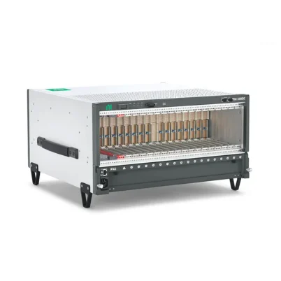

PXIe-1086 18-Slot Redundant PXI Express Chassis
Земля NI PXIe-1086 is an 18-slot PXI Express chassis designed for automated test, measurement and control systems that require high channel capacity and dependable continuous operation. It provides 16 hybrid peripheral slots, one PXI Express system timing slot and one dedicated system-controller slot.
The PXIe-1086 delivers up to 12 GB/s maximum system bandwidth and as much as 855 W of usable power. Its hot-swappable redundant AC power supplies and front-accessible redundant cooling fans help reduce system downtime and simplify maintenance in production, validation and long-duration test installations.
Integrated monitoring tracks power-supply health, voltage conditions, air-intake temperature, fan health and fan speed. Chassis status indicators provide visible notification of detected faults, helping operators identify developing power or cooling problems before they interrupt a critical test process.
Key Features of the PXIe-1086
- 18-slot 3U PXI Express chassis
- One dedicated system-controller slot
- 16 hybrid peripheral slots
- One PXI Express system timing slot
- Up to 12 GB/s maximum system bandwidth
- 855 W maximum total usable power
- Hot-swappable redundant AC power-supply architecture
- Power-supply shuttle replacement in less than one minute
- Hot-swappable front-accessible redundant cooling fans
- Six 150 CFM chassis fans arranged as three dual-fan assemblies
- 38.25 W maximum peripheral-slot dissipation
- 140 W maximum system-controller-slot dissipation
- Internal 10 MHz and 100 MHz reference clocks
- External 10 MHz reference input and output
- PXI star and differential star trigger resources
- Power-supply, voltage, temperature and fan monitoring
- Front-panel chassis status indicators
- Universal 100 VAC to 240 VAC input
- Compatible with rack-mounted automated test systems
PXIe-1086 Technical Specifications
| Product Model | PXIe-1086 |
|---|---|
| Part Number | 781720-01 |
| Product Type | Redundant PXI Express chassis |
| Chassis Format | 3U, 18-slot PXI Express chassis |
| Total Physical Slots | 18 |
| System-Controller Slots | 1 |
| Hybrid Peripheral Slots | 16 |
| PXI Express System Timing Slots | 1 |
| Maximum System Bandwidth | Up to 12 GB/s |
| Maximum Total Usable Power | 855 W |
| Maximum Controller-Slot Dissipation | 140 W |
| Maximum Peripheral-Slot Dissipation | 38.25 W |
| Power-Supply Type | AC, hot-swappable redundant architecture |
| Nominal Input Voltage | 100 VAC to 240 VAC |
| Operating Voltage Range | 90 VAC to 264 VAC |
| Input Current Rating | 12 A to 6 A |
| Nominal Input Frequency | 50/60 Hz |
| Operating Frequency Range | 47 Hz to 63 Hz |
| Typical Power-Supply Efficiency | 70% |
| Power-Supply Replacement Time | Less than one minute |
| Cooling System | Forced-air positive-pressurization cooling |
| Chassis Cooling Fans | Six 150 CFM fans in three dual-stacked assemblies |
| Fan-Speed Modes | Auto and High |
| Module Airflow Direction | Bottom to top |
| Module Cooling Intake | Bottom of chassis |
| Module Cooling Exhaust | Top of chassis |
| System Timing Slot | Да |
| External Clocking | Да |
| Integrated External Trigger Access | No |
| Onboard Clock Type | VCXO |
| PXI_CLK10 Accuracy | ±25 ppm maximum |
| PXI_CLK10 Slot-to-Slot Skew | 1 ns maximum |
| PXIe_CLK100 Accuracy | ±25 ppm maximum |
| PXIe_CLK100 Slot-to-Slot Skew | 100 ps maximum |
| PXI Star Trigger Slot-to-Slot Skew | 250 ps maximum |
| PXI Differential Star Trigger Skew | 150 ps maximum between slots |
| External Reference Output | 10 MHz through rear-panel BNC |
| External Reference Input | 10 MHz ±100 ppm |
| Operating Temperature | 0°C to 50°C |
| Operating Humidity | 5% to 95%, noncondensing |
| Storage Temperature | −40°C to 71°C |
| Storage Humidity | 5% to 95%, noncondensing |
| Maximum Operating Altitude | 4,600 m at 25°C with High fan mode |
| Operational Shock | 30 g peak, half-sine, 11 ms pulse |
| Operational Random Vibration | 5 Hz to 500 Hz, 0.3 grms |
| Auto-Fan Sound Pressure | 57.0 dBA at up to approximately 30°C ambient |
| High-Fan Sound Pressure | 69.0 dBA |
| Dimensions | 268.7 × 467.1 × 476.5 mm |
| Weight with Two Power Supplies | 17.1 kg |
| Weight with One Power Supply | 14.3 kg |
| Intended Environment | Indoor use |
PXIe-1086 Part Number and Accessories
| Item | Part Number | Описание |
|---|---|---|
| PXIe-1086 | 781720-01 | 18-slot, 12 GB/s redundant AC PXI Express chassis |
| Power-Supply Filler Panel | 784057-01 | Required in the unused power-supply position when operating with one supply under specified shock and vibration conditions |
| Single-Slot Filler Panels | Included | Seven single-slot panels supplied with the chassis |
| Double-Slot Filler Panel | Included | One double-slot panel supplied with the chassis |
| Quadruple-Slot Filler Panels | Included | Two quadruple-slot panels supplied with the chassis |
| Mini-COMBICON Connector Plug | Included | Connector for compatible chassis power-control functions |
| Front Rack-Mount Kit | Configuration dependent | Mounting brackets for front-facing rack installation |
| Rear Rack-Mount Kit | Configuration dependent | Rear mounting support for compatible instrument cabinets |
| Replacement AC Power Supply | Configuration dependent | Hot-swappable replacement or additional redundant supply |
| Replacement Fan Module | Configuration dependent | Front-accessible hot-swappable cooling-fan assembly |
The standard package includes the chassis, seven single-slot filler panels, one double-slot filler panel, two quadruple-slot filler panels, a Mini-COMBICON connector plug and the applicable safety and regulatory documentation.
Because the PXIe-1086 can be configured with one or two power supplies, confirm the installed power-supply quantity, redundant operating requirement, power cord, rack hardware and replacement components before ordering.
18-Slot PXI Express Architecture
The PXIe-1086 provides one system-controller position and 17 peripheral positions. Sixteen peripheral positions use hybrid connectors, while the remaining position is a dedicated PXI Express system timing slot.
This high slot count allows one chassis to accommodate a substantial collection of measurement and control hardware. Systems can combine digitizers, signal generators, RF instruments, switching modules, data acquisition devices, programmable power supplies and communication interfaces without dividing the configuration across several smaller chassis.
The system slot includes space for a controller and as many as three system-slot expansion positions. A wide embedded controller can occupy adjacent physical slots, so its width must be included when calculating the number of remaining peripheral positions.
Sixteen Hybrid Peripheral Slots
The 16 hybrid peripheral slots accept compatible PXI Express instruments and hybrid-compatible conventional PXI modules. This provides more placement flexibility than a chassis containing mainly PXI Express-only peripheral connectors.
The hybrid architecture is useful when upgrading an established test system. Supported legacy PXI modules can be retained while newer PXI Express instruments are added for higher-speed acquisition, signal processing or data transfer.
Physical fit does not guarantee complete compatibility. Verify the module connector, voltage signaling, power demand, driver support and operating-system requirements before installation.
Dedicated System Timing Slot
The PXIe-1086 includes a dedicated PXI Express system timing slot for compatible timing and synchronization modules. This slot provides access to specialized clocking and differential star-trigger resources.
A timing module can be used to distribute or receive reference clocks, coordinate triggers and improve synchronization among instruments in the chassis. This capability is important in phase-coherent acquisition, multichannel digitizer systems and synchronized stimulus-and-response testing.
When several PXI chassis must operate together, a compatible timing module can help distribute common timing signals between systems. The complete synchronization design should account for cable delay, module delay, trigger routing and clock accuracy.
12 GB/s System Bandwidth
The PXIe-1086 provides up to 12 GB/s of aggregate system bandwidth between the controller and chassis backplane. This supports simultaneous communication with multiple PXI Express instruments.
Actual application throughput depends on the controller, backplane topology, module link widths, storage performance and number of devices transferring data at the same time.
For continuous streaming applications, calculate the required data rate of each digitizer, FPGA device and waveform instrument. Modules with modest command and status traffic can share resources more easily than high-speed instruments performing sustained DMA transfers.
855 W Total Usable Power
The chassis provides up to 855 W of total usable backplane power. This supports large configurations containing many measurement, switching and control modules.
Power budgeting must consider individual voltage rails as well as total wattage. With one power supply, the specified maximum currents include 50 A at +3.3 V, 40 A at +5 V and 50 A at +12 V. With two supplies, the available current increases, subject to the total usable-power limit and system operating conditions.
The power outputs include short-circuit and overload protection with automatic recovery. Over-voltage protection is also provided on the 3.3 V and 5 V rails.
Hot-Swappable Redundant AC Power Supplies
The PXIe-1086 supports dual hot-swappable AC power supplies. When both supplies are installed and the system load remains within the redundancy limit, one supply can maintain chassis operation if the other supply fails or is removed.
This architecture helps reduce unplanned downtime in manufacturing, qualification and continuously operating test systems. A failed power-supply shuttle can be replaced in less than one minute without dismantling the chassis.
Redundancy does not automatically guarantee uninterrupted operation under every load. Confirm that either individual supply can support the installed system load and that both AC inputs receive suitable power.
Single-Power-Supply Operation
The PXIe-1086 can also operate with one power supply. However, the system will not retain power-supply redundancy, and the available current differs from the dual-supply configuration.
When only one supply is installed, the empty position must use the specified power-supply filler panel, part number 784057-01, to meet the documented operational shock and vibration requirements.
The filler panel also helps protect the open supply bay and maintain the intended airflow through the chassis.
Hot-Swappable Redundant Cooling
The module area uses six 150 CFM fans arranged as three sets of dual-stacked fans. The redundant design helps preserve cooling when one fan in an assembly develops a fault.
The fan modules are accessible from the front and can be serviced without completely dismantling a rack installation. This design reduces mean time to repair in systems where maintenance access is limited.
Fan redundancy should not be treated as permission to continue indefinitely with a failed fan. Replace a defective assembly promptly and monitor chassis temperature during maintenance.
Positive-Pressurization Airflow
Cooling air enters from the bottom of the chassis and flows upward through the installed modules before leaving through the top. Positive pressurization helps deliver cooling air through each instrument slot.
The power supplies use integrated cooling fans with air entering at the rear and exhausting through the top of the chassis.
Unused slots must be covered with filler panels. Open positions allow air to bypass installed instruments, which can reduce cooling performance and create uneven module temperatures.
Chassis Monitoring and Fault Indicators
The PXIe-1086 monitors power-supply health, supply voltages, air-intake temperature, cooling-fan health and fan speed. Chassis status LEDs provide immediate visual feedback when the monitoring system detects a failure.
This information helps operators distinguish between a power, fan or temperature problem. In unattended installations, the test application can incorporate chassis-health monitoring into the overall system-maintenance strategy.
Operators should establish an appropriate response procedure for warnings, including saving test data, placing the DUT in a safe state and scheduling replacement of the affected component.
External 10 MHz Reference Clock
A rear-panel BNC connector provides a 10 MHz reference-clock output. The output has a specified amplitude of 1 Vpp into 50 Ω and an output impedance of 50 Ω.
The chassis also accepts an external 10 MHz reference source. This allows the backplane reference clock to be related to an external laboratory standard or other compatible test equipment.
The external source must remain within the specified frequency, amplitude and impedance limits. Clock distribution cables should use the proper impedance and termination to limit reflections and timing errors.
PXI and PXI Express Timing Resources
The backplane distributes PXI_CLK10 as well as PXIe_CLK100 and PXIe_SYNC100. PXI_CLK10 provides ±25 ppm accuracy and a maximum slot-to-slot skew of 1 ns.
PXIe_CLK100 provides ±25 ppm accuracy with maximum slot-to-slot skew of 100 ps. The PXI star trigger has a maximum slot-to-slot skew of 250 ps, while PXI differential star triggering supports a maximum slot-to-slot skew of 150 ps.
These backplane resources support repeatable coordination between compatible modules. Final measurement synchronization also depends on the instruments, routes, cables and software configuration.
Remote Power-Control Capability
The chassis includes a front-panel four-pin terminal-block connection and power-mode selector that can be used with supported power-control functions.
This allows the PXIe-1086 to be integrated into larger test racks where the chassis must follow a centralized startup, shutdown or safety-control sequence.
Power-control wiring must follow the user manual and applicable electrical-safety practices. The AC cord remains the main means of fully disconnecting power.
Embedded and Remote Controller Options
A compatible PXI Express embedded controller can be installed to create a self-contained measurement system. The embedded architecture is suitable when computing, instrument control and data storage must remain inside the rack.
A remote-control module can connect the chassis to an external workstation or industrial computer. This may provide greater flexibility for processor selection, data storage, graphics hardware and integration with existing IT systems.
The correct controller architecture depends on bandwidth, operating-system, processing, cable-distance and service requirements.
Rack-Mount System Integration
The PXIe-1086 is designed for large benchtop and rack-mounted systems. Front and rear mounting-hole patterns allow compatible rack hardware to be installed according to the required equipment orientation.
The chassis requires at least 44.45 mm of clearance above and on both sides, plus at least 76.20 mm behind it. Cable routing and nearby equipment must not obstruct the bottom intake or top exhaust.
Because a dual-supply chassis weighs approximately 17.1 kg before modules and cables are added, use suitable rack support and follow safe lifting procedures.
PXIe-1086 Applications
- High-availability automated test equipment
- Continuous production functional testing
- Large mixed-signal validation systems
- Semiconductor characterization
- Aerospace and defense electronic testing
- Automotive ECU and HIL validation
- RF and wireless-device testing
- High-channel-count data acquisition
- Power-electronics validation
- Long-duration reliability testing
- Research laboratory automation
- Multi-instrument stimulus-and-response systems
High-Availability Production Testing
The redundant power and cooling architecture makes the PXIe-1086 particularly suitable for production lines where unexpected chassis downtime can interrupt output and delay delivery.
A failed supply or fan assembly can be serviced quickly, while integrated health monitoring gives maintenance personnel information about the affected component.
Large Automated Test Systems
The 17 peripheral positions allow many instrument types to share one controller and backplane. A system can combine signal generation, switching, measurement, communication and power-control hardware without requiring several smaller chassis.
Centralizing the hardware can simplify triggering, cabling and software coordination, although the complete power and bandwidth budget must still be verified.
High-Channel-Count Data Acquisition
Multiple analog input, digital I/O, temperature, strain or dynamic-signal modules can be installed to build a high-channel-count acquisition system.
The 12 GB/s backplane supports data transfer from several instruments, while the timing resources help coordinate sampling across compatible modules.
Aerospace and Defense Validation
Aerospace test systems often require many signal types, deterministic timing and long operating periods. The PXIe-1086 can host avionics interfaces, DAQ hardware, switches, FPGA modules and stimulus instruments in one chassis.
The system timing slot and external reference clock connections help integrate the PXI system into a synchronized laboratory environment.
Automotive ECU and HIL Testing
The chassis can combine vehicle-network interfaces, fault-insertion switches, FPGA devices, programmable power instruments and acquisition modules for ECU validation.
Power and cooling redundancy can be useful during extended HIL regression tests where an interruption would require a long sequence to be restarted.
RF and Wireless Testing
Signal generators, vector signal analyzers, RF downconverters and switching modules can be combined for wireless component and subsystem testing.
For high-volume RF streaming, verify that the 12 GB/s system bandwidth and individual module connections meet the aggregate data-rate requirement.
Reliability and Environmental Testing
Long-duration tests may run continuously for days or weeks. The replaceable power and cooling assemblies help maintenance teams address component faults while reducing the time required to restore full redundancy.
The test software should still save data regularly and define a controlled DUT shutdown procedure for serious temperature or power events.
PXIe-1086 Installation Workflow
Step 1: Inspect the Chassis and Accessories
Check the chassis, power-supply modules, fans, filler panels, terminal-block plug and rack hardware for shipping damage. Confirm that the chassis part number is 781720-01.
Step 2: Create a Slot Map
List the controller, timing module and every peripheral instrument. Record each module’s width, connector type, bandwidth, power and cooling requirements.
Reserve the System Timing Slot
Install the timing module only in the dedicated system timing position when the application requires access to PXI Express differential star resources.
Account for Wide Modules
Controllers and instruments wider than one slot reduce the remaining usable capacity. Include connector clearance and front-panel cable space in the slot map.
Step 3: Calculate the Power Budget
Confirm that the combined configuration remains within the 855 W usable-power limit and the current ratings of the individual voltage rails.
For redundant operation, make sure either power supply can sustain the intended load if the second supply is removed or fails.
Step 4: Prepare the Installation Location
Place the chassis on a stable bench or install it using compatible front and rear rack hardware. Maintain the required top, side and rear clearances.
Do not position equipment beneath the chassis in a way that blocks its bottom air intake.
Step 5: Connect Protective Ground
Connect the approved regional AC power cord to a grounded outlet. Keep the connector accessible because removing the cord is the primary method of completely disconnecting AC power.
Step 6: Power Off Before Installing Modules
Keep the chassis switched off while installing the controller, timing module and peripheral devices. Follow antistatic precautions and handle modules only by their approved surfaces.
Step 7: Install the System Controller
Insert the embedded controller or remote-control interface into the system slot. Align the module with the guides, seat the backplane connectors fully and tighten the retaining screws.
Step 8: Install the Timing and Peripheral Modules
Install the system timing module in its dedicated position and place the remaining instruments according to the prepared slot map.
Verify that every peripheral module dissipates no more than 38.25 W and that all hybrid-slot modules use compatible connectors.
Step 9: Install Filler Panels
Cover all unused instrument positions with appropriately sized filler panels. If only one power supply is used, install the required 784057-01 power-supply filler panel.
Step 10: Connect Power and Signal Cables
Connect both AC power supplies when redundant operation is required. Where practical, use suitable independent branch circuits so that a single upstream failure does not remove both inputs.
Connect instrument cables, the external clock source and remote power-control wiring only according to the applicable hardware documentation.
Step 11: Power On and Check Status
Turn on the chassis and controller. Confirm that the power-supply and fan indicators show normal operation and that no temperature or voltage fault is reported.
Step 12: Detect and Verify the Hardware
Use NI Measurement & Automation Explorer to verify the controller, chassis and installed instruments. Install the required device drivers and run the available self-tests before connecting a valuable DUT.
PXIe-1086 Troubleshooting
The PXIe-1086 Does Not Power On
Confirm that the AC cords are securely connected and that the outlets provide power within the specified voltage and frequency range. Check the front-panel power switch and configured power-control mode.
If remote power control is used, inspect the Mini-COMBICON wiring and confirm that an external inhibit signal is not preventing startup.
One Power Supply Reports a Fault
Check its AC input, status indicator and seating within the supply bay. Confirm that the second supply is carrying the system without exceeding its capacity.
Replace a defective hot-swappable supply promptly to restore redundancy. Follow the service instructions and use the correct replacement model.
The Chassis Shuts Down When a Supply Is Removed
The installed system load may exceed the capacity available from one supply, or the remaining supply may not be receiving AC power.
Review the single-supply current limits and reduce the load before testing redundancy again.
A Cooling-Fan Fault Is Displayed
Identify the affected fan assembly from the status information. Check for blocked airflow or foreign material and replace the failed front-accessible fan module as soon as possible.
Monitor temperature during service because the remaining fan preserves availability only within the supported operating conditions.
The Chassis Reports Excessive Temperature
Check the bottom air intake, top exhaust and required installation clearances. Confirm that filler panels cover all unused slots and that all fans operate correctly.
Reduce ambient temperature or module load when necessary. Use High fan mode in elevated-temperature or high-altitude installations.
An Installed Module Is Not Detected
Power down the chassis and reseat the module. Confirm that it is installed in a compatible hybrid or PXI Express position and that the correct driver is installed.
Use NI MAX to rescan the hardware. Moving the module to another compatible slot can help distinguish a module issue from a slot or configuration problem.
Data Throughput Is Lower Than Expected
Review the controller, module link widths, backplane topology and combined streaming rate. The 12 GB/s specification is an aggregate chassis maximum and does not guarantee that every slot can transfer at that rate.
Storage performance, CPU load, DMA configuration and concurrent transfers can also limit sustained acquisition speed.
Modules Do Not Synchronize Correctly
Verify the reference-clock source, timing-module configuration, trigger routing and termination. Confirm that the external source is 10 MHz and remains within the specified frequency and amplitude limits.
Account for cable and module delays when precise phase alignment is required.
The Fans Are Louder Than Expected
The chassis produces approximately 57 dBA in Auto mode under specified lower-temperature conditions and approximately 69 dBA in High mode.
High fan speed may be required by ambient temperature, altitude or the selected operating mode. Do not reduce cooling performance solely to lower acoustic noise.
A Legacy PXI Module Does Not Fit
Not every conventional PXI module uses a hybrid-compatible connector. Check the module hardware documentation before installation and never force a card into the backplane.
PXIe-1086 Comparison
| Функция | PXIe-1086 | PXIe-1086DC | PXIe-1085 | PXIe-1095 |
|---|---|---|---|---|
| Общее количество слотов | 18 | 18 | 18 | 18 |
| Hybrid Peripheral Slots | 16 | 16 | 16 | 5 |
| System Timing Slot | Да | Да | Да | Да |
| Maximum System Bandwidth | 12 GB/s | 12 GB/s | Up to 24 GB/s | 24 ГБ/с |
| Maximum Slot Cooling | 38.25 W | 38.25 W | 38 Вт | 82 Вт |
| Power Input | AC | DC and supported AC input | AC | AC |
| Redundant Hardware | Да | Да | No | Да |
| Primary Advantage | High availability and broad hybrid-slot compatibility | Redundant architecture for DC-powered installations | Higher bandwidth with all-hybrid layout | Higher bandwidth, power and per-slot cooling |
PXIe-1086 vs PXIe-1086DC
The two chassis share an 18-slot architecture, 16 hybrid peripheral slots, a system timing slot and up to 12 GB/s of bandwidth.
The principal difference is the intended power architecture. The PXIe-1086 is the AC-focused version, while the PXIe-1086DC supports redundant DC power for specialized installations. Select the version that matches the facility power source and redundancy design.
PXIe-1086 vs PXIe-1085
The PXIe-1085 provides up to 24 GB/s of bandwidth and an all-hybrid peripheral architecture, but it does not offer the PXIe-1086 hot-swappable redundant-hardware design.
Choose the PXIe-1086 when serviceability and system uptime are more important than maximum bandwidth. Choose the PXIe-1085 when higher data throughput is required and redundant power and cooling are not essential.
PXIe-1086 vs PXIe-1095
The PXIe-1095 is a newer high-performance chassis providing up to 24 GB/s of bandwidth and as much as 82 W of power and cooling per slot. It also supports hot-swappable power supplies.
The PXIe-1086 provides more hybrid-compatible peripheral positions and is useful for systems containing numerous supported conventional PXI modules. The PXIe-1095 is preferable for newer, higher-power PXI Express instrumentation.
Selecting the Right 18-Slot PXI Chassis
Choose the PXIe-1086 when the system requires 16 hybrid slots, 12 GB/s bandwidth, redundant AC power and serviceable cooling hardware.
Select a 24 GB/s chassis when several high-speed digitizers, RF instruments or FPGA devices must stream concurrently. Choose the PXIe-1086DC when the installation requires redundant DC input.
Why Choose the PXIe-1086?
- Provides 17 peripheral positions in one chassis
- Supports 16 hybrid-compatible instrument slots
- Delivers up to 12 GB/s system bandwidth
- Provides up to 855 W of usable power
- Supports hot-swappable redundant AC supplies
- Includes redundant front-accessible cooling fans
- Monitors supply health, voltage, temperature and fan operation
- Includes a dedicated PXI Express system timing slot
- Supports external 10 MHz reference input and output
- Reduces repair time in high-availability test installations
PXIe-1086 Frequently Asked Questions
What is the PXIe-1086?
The PXIe-1086 is an 18-slot PXI Express chassis designed for high-availability automated test, measurement and control applications.
What is the PXIe-1086 part number?
The standard NI part number is 781720-01.
How many peripheral slots does it provide?
It provides 17 peripheral positions: 16 hybrid slots and one PXI Express system timing slot. One additional position is reserved for the system controller.
What is the maximum system bandwidth?
The PXIe-1086 supports up to 12 GB/s of aggregate system bandwidth.
What is the maximum available power?
The chassis provides up to 855 W of total usable power, subject to the individual voltage-rail and slot-current limits.
Does the PXIe-1086 support redundant power supplies?
Yes. It supports hot-swappable redundant AC power supplies. For genuine redundancy, the complete system load must remain within the capacity that one supply can sustain.
Can a power supply be replaced while the system is operating?
Yes, when a properly configured redundant supply remains installed and can carry the complete load. The specified replacement time for the power-supply shuttle is less than one minute.
Can the chassis operate with one power supply?
Yes, but power redundancy is lost and the single-supply current limits apply. The empty bay requires power-supply filler panel 784057-01 to meet the documented shock and vibration specifications.
Are the cooling fans redundant?
Yes. The chassis uses six fans arranged as three dual-stacked assemblies. The fan modules are front accessible and hot swappable.
What is the maximum cooling capacity per slot?
The maximum permitted peripheral-slot power dissipation is 38.25 W. The system-controller position supports up to 140 W.
Does it have a system timing slot?
Yes. The PXIe-1086 includes one dedicated PXI Express system timing slot for compatible clocking and synchronization modules.
Does the chassis support an external reference clock?
Yes. It supports a 10 MHz external reference input and provides a rear-panel 10 MHz reference output.
Can conventional PXI modules be installed?
Compatible hybrid-connector PXI modules can be installed in the 16 hybrid peripheral slots. Each module must be checked for physical, electrical and driver compatibility.
Can the PXIe-1086 be rack mounted?
Yes. Compatible front and rear rack-mount kits can be used. The rack must provide proper support and preserve the required intake and exhaust clearances.
What is the current NI lifecycle status?
NI currently lists the PXIe-1086 under Standard Support and indicates that it is no longer available for direct purchase. Procurement may therefore depend on remaining new inventory, unused surplus units or professionally tested used equipment.
Recommended Related Products
- PXIe-1086DC 18-Slot Redundant DC PXI Express Chassis
- PXIe-1085 18-Slot 24 GB/s PXI Express Chassis
- PXIe-1095 18-Slot High-Power PXI Express Chassis
- PXIe-1088 9-Slot All-Hybrid PXI Express Chassis
- PXIe-6674T Timing and Synchronization Module
- PXIe-8842 Embedded Controller
- PXIe-8862 Embedded Controller
- View More NI PXI and PXI Express Chassis
- View More NI PXI and PXI Express Modules
Request a Quote for the PXIe-1086
Contact us for current stock, condition, lead time and project pricing for the NI PXIe-1086 18-Slot Redundant PXI Express Chassis. We can also help identify compatible power supplies, fan modules, rack-mount hardware, embedded controllers, timing modules and PXI instrumentation for your test system.















