






Product Introduction
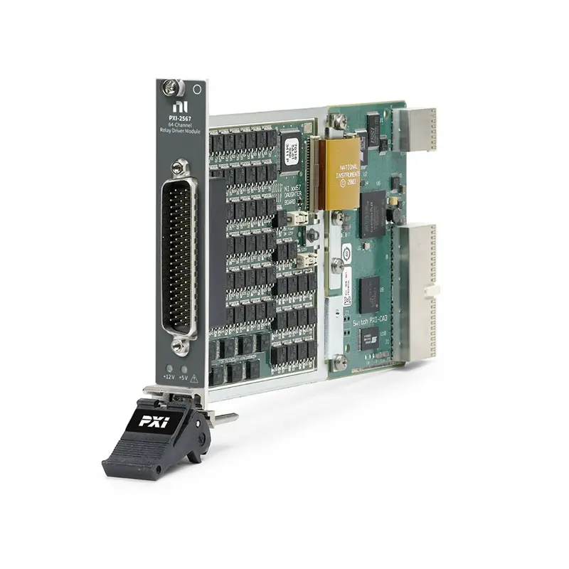
The NI PXI-2567 is a 64-channel PXI external relay driver module designed for controlling external relays, small DC motors, inductive relay coils, and other compatible external switching devices in automated test and control systems.
Unlike a conventional PXI relay switch module, the PXI-2567 does not primarily route measurement signals through onboard relay contacts. Instead, it provides 64 independent relay-driver channels that can control external relays when the voltage, current, contact configuration, or switching requirements exceed the capabilities of standard integrated PXI relay modules.
With an external power supply, the PXI-2567 supports drive voltages up to 50 VDC and drive current up to 600 mA per channel. The module supports up to 25 A total drive current and incorporates overcurrent, overvoltage, overtemperature, and flyback protection for reliable control of inductive loads.
Product Overview
The National Instruments PXI-2567 provides a flexible interface between a PXI automated test system and externally mounted relays or other compatible loads.
A typical system architecture is:
PXI Controller → PXI-2567 → External Relay Coil → External Relay Contacts → DUT Signal
In this architecture, the PXI-2567 controls the relay coil while the external relay contacts perform the actual signal switching.
This allows system designers to select external relays according to the specific electrical requirements of the application, including:
- High-current switching
- High-voltage switching
- RF signal switching
- Multipole switching
- Power switching
- Custom switching topologies
Key Features
64 Independent Relay Driver Channels
The PXI-2567 provides 64 independent relay-driver channels.
The channels are organized into eight banks of eight channels, providing high channel density for automated relay-control applications.
This architecture is useful when a test system contains many externally mounted relays that need to be controlled independently through software.
Up to 50 VDC External Drive Voltage
When used with an appropriate external power supply, the PXI-2567 supports a maximum external drive voltage of 50 VDC.
This allows the module to control compatible relay coils requiring drive voltages beyond the internal PXI backplane supply options.
The actual external supply voltage should always match the electrical requirements of the connected relay or load.
Up to 600 mA Drive Current Per Channel
Each PXI-2567 driver channel supports up to 600 mA maximum drive current.
This relatively high per-channel current capability allows the module to drive many types of external relay coils and compatible inductive loads.
The connected load must remain within both the individual channel limit and total module current limit.
Up to 25 A Total Module Drive Current
The PXI-2567 supports up to 25 A maximum total module drive current when operating within the specified electrical and thermal conditions.
System designers should evaluate simultaneous channel activation carefully when a large number of high-current relay coils are energized at the same time.
Internal 5 V and 12 V Drive Power
The PXI-2567 can use power available from the PXI backplane for compatible low-power relay-drive applications.
Internal drive power includes:
- 5 V at up to 1.25 A
- 12 V at up to 0.5 A
For applications requiring higher voltage or greater total drive power, an appropriate external power supply can be used.
External Power Supply Support
One of the major advantages of the PXI-2567 is its ability to operate with an external power source.
This provides additional flexibility when external relays require different coil voltages or greater drive power than the PXI backplane can provide.
A typical architecture is:
External DC Supply + PXI-2567 Driver Channel → Relay Coil
Overcurrent Protection
The PXI-2567 includes per-channel protection circuitry for abnormal current conditions.
This helps protect the relay-driver circuitry when connected loads create excessive current conditions.
Overvoltage Protection
The module also incorporates overvoltage protection.
According to the PXI-2567 specifications, the per-channel overvoltage protection circuitry activates at up to approximately 80 V maximum.
This protection threshold should not be interpreted as the normal operating voltage. The specified maximum external drive voltage remains 50 VDC.
Flyback Protection for Inductive Loads
Relay coils, motors, solenoids, and similar inductive devices can generate voltage transients when current is interrupted.
The PXI-2567 incorporates protection against these inductive flyback conditions.
This makes the module particularly suitable for controlling:
- Relay coils
- Small DC motors
- Solenoid-type loads
- Other compatible inductive devices
Overtemperature Protection
The PXI-2567 includes thermal protection circuitry to help protect the driver electronics from excessive operating temperatures.
Thermal loading should still be considered when many high-current channels operate simultaneously.
Fast Channel Operation
The PXI-2567 provides a typical single-channel operate time of approximately 60 μs under specified test conditions.
The module is therefore capable of rapidly controlling external relay-drive signals as part of automated test sequences.
Hardware Scanning
The PXI-2567 supports scanning functionality for automated test applications.
A predefined list of relay-driver connections can be downloaded to the switching hardware and executed according to hardware triggers.
This reduces host-processor interaction and can improve throughput in automated test systems.
78-Pin D-SUB Connectivity
The PXI-2567 uses a 78-pin D-SUB connector for its primary external relay-driver connections.
Appropriate mating connectors, backshells, cables, or custom interface assemblies can be used to connect the module to external relay banks and test-system wiring.
Technical Specifications
| Parameter | Specification |
|---|---|
| Product Type | PXI External Relay Driver Module |
| Model | NI PXI-2567 |
| Part Number | 778572-67 |
| Platform | PXI |
| Number of Driver Channels | 64 |
| Channel Organization | 8 Banks × 8 Channels |
| Topology | Independent Relay Drivers |
| Maximum External Drive Voltage | 50 VDC |
| Maximum Drive Current Per Channel | 600 mA |
| Maximum Total Module Drive Current | 25 A |
| Internal 5 V Drive Power | 5 V at 1.25 A |
| Internal 12 V Drive Power | 12 V at 0.5 A |
| Typical Single-Channel Operate Time | 60 μs |
| Channel-to-Ground Resistance | 0.280 Ω Maximum at 0 to 600 mA Drive Current |
| Overvoltage Protection | Per Channel |
| Overcurrent Protection | Per Channel |
| Overtemperature Protection | Supported |
| Flyback Protection | Supported |
| External Power Supply | Supported |
| Primary Connector | 78-Pin D-SUB |
| Primary Applications | External Relay Control, Inductive Load Control, Custom Switching Systems and Automated Test |
What Is a Relay Driver Module?
A relay driver module provides the electrical drive signal required to energize or de-energize external relay coils.
It is important to distinguish between a relay driver and a relay switch module.
| Function | Relay Driver | Relay Switch Module |
|---|---|---|
| Controls External Relay Coil | Yes | Usually No |
| Contains Main Signal Relay Contacts | No | Yes |
| Routes DUT Signal Directly | Through External Relay | Through Onboard Relay |
| Switch Topology | Determined by External Relay | Fixed by Module Design |
| Application Flexibility | Very High | Topology Dependent |
How Does the PXI-2567 Work?
The PXI-2567 acts as an interface between software commands from the PXI system and external relay coils.
A simplified signal chain is:
Test Software → PXI-2567 Driver → External Relay Coil → Relay Contact Changes State → DUT Signal Routed
The PXI-2567 controls the coil. The electrical characteristics of the actual switched DUT signal are primarily determined by the external relay selected by the system designer.
Why Use External Relays?
Standard PXI switch modules are convenient when their built-in relay topology and electrical specifications meet the application requirements.
However, some test systems require specialized relays for:
- Higher switching current
- Higher switching voltage
- RF and microwave signals
- Multiple poles
- Special contact arrangements
- High-power switching
- Custom fault insertion
- Application-specific isolation
The PXI-2567 allows these external relays to remain under software control from the PXI system.
External Relay Control
External relay control is the primary application of the PXI-2567.
Each driver channel can control a compatible relay coil independently.
For example:
PXI-2567 Channel 0 → Relay 0 Coil
PXI-2567 Channel 1 → Relay 1 Coil
PXI-2567 Channel 2 → Relay 2 Coil
…
PXI-2567 Channel 63 → Relay 63 Coil
This provides centralized software control for large custom relay assemblies.
High-Current External Relay Systems
The PXI-2567 can control external relays whose contacts are designed to switch currents beyond the capabilities of conventional PXI switch modules.
In this configuration:
PXI-2567 → Controls Relay Coil
External Relay → Switches High-Current DUT Circuit
The PXI-2567 itself does not carry the high-current DUT signal through its relay-driver channel.
This distinction is important when designing power switching and fault-insertion systems.
High-Voltage External Relay Systems
External relays can also be selected for applications requiring switching voltages beyond the direct signal-switching capabilities of standard PXI relay modules.
The PXI-2567 controls only the external relay coil, while the external relay contacts handle the DUT signal.
Therefore, the maximum DUT switching voltage is determined by the selected external relay and the complete system design rather than by treating the PXI-2567 as a direct high-voltage signal switch.
RF Relay Control
The PXI-2567 can control compatible external RF relays or RF switching assemblies.
A typical architecture is:
PXI-2567 → RF Relay Coil
RF Instrument → RF Relay Contacts → DUT
This allows specialized RF relays to be incorporated into a PXI-controlled automated RF test system.
RF bandwidth, insertion loss, isolation, VSWR, RF power, and connector characteristics are determined primarily by the external RF relay and associated signal path.
Small DC Motor Control
The PXI-2567 can also drive compatible small DC motors within its specified voltage and current limits.
This capability can be useful in automated test fixtures containing small mechanical actuators or positioning mechanisms.
Motor starting current and inductive characteristics should be evaluated carefully before connecting the load.
Inductive Load Control
The PXI-2567 is particularly useful for loads with inductive characteristics.
Examples can include:
- Relay coils
- Small DC motors
- Compatible solenoids
- Electromagnetic actuators
Its integrated flyback protection helps manage voltage transients generated when current through an inductive load is interrupted.
PXI-2567 for Automated Test Equipment
Automated test equipment often contains custom switching assemblies that cannot be implemented efficiently with standard PXI switch modules.
The PXI-2567 provides a scalable way to control these external switching devices directly from the PXI system.
Typical ATE applications include:
- Automotive ECU testing
- Electronic module validation
- Power electronics testing
- Aerospace electronics test
- Fault insertion systems
- Production functional test
- Custom relay matrices
Fault Insertion Applications
The PXI-2567 can control external relays used to implement custom fault-insertion architectures.
Depending on the external relay arrangement, a system can simulate conditions such as:
- Open circuits
- Short circuits
- Signal disconnection
- Power interruption
- Alternate signal routing
- Custom electrical faults
This architecture can be useful for hardware-in-the-loop, automotive electronics, aerospace electronics, and system validation applications.
PXI-2567 for Automotive Test
Automotive electronic control unit testing frequently requires large custom relay systems for signal routing and fault simulation.
The PXI-2567 can control external automotive-grade relays selected according to the voltage, current, isolation, and contact requirements of the test system.
Typical applications can include:
- ECU functional testing
- Power distribution testing
- Open-circuit simulation
- Short-circuit simulation
- Sensor fault simulation
- Actuator control
- Hardware-in-the-loop systems
Internal vs External Drive Power
The PXI-2567 provides flexibility in how external relay coils are powered.
| Power Method | Capability | Typical Application |
|---|---|---|
| Internal 5 V Supply | 5 V / 1.25 A Total | Low-Power 5 V Relay Coils |
| Internal 12 V Supply | 12 V / 0.5 A Total | Low-Power 12 V Relay Coils |
| External Supply | Up to 50 VDC | Higher-Power or Different-Voltage Relay Coils |
The appropriate power architecture depends on relay coil voltage, coil current, number of simultaneously energized channels, and total system power requirements.
PXI-2567 vs PXI-2568
Although the model numbers are similar, the PXI-2567 and PXI-2568 perform fundamentally different functions.
| Feature | PXI-2567 | PXI-2568 |
|---|---|---|
| Product Type | External Relay Driver | General-Purpose Relay Switch |
| Channels | 64 Driver Channels | 31 Relay Channels |
| Relay Contacts Onboard | No Main Signal Contacts | Yes |
| Topology | Independent Drivers | SPST Relays |
| Primary Function | Drive External Relays | Directly Switch DUT Signals |
| Best Application | Custom External Switching Systems | General-Purpose Signal Switching |
PXI-2567 vs PXI-2566
| Feature | PXI-2567 | PXI-2566 |
|---|---|---|
| Product Type | Relay Driver | Relay Switch Module |
| Channels | 64 | 16 |
| Switch Configuration | External Relay Dependent | SPDT |
| Direct DUT Signal Switching | No | Yes |
| External Relay Control | Primary Function | Not Primary Function |
| Application Flexibility | Very High | Fixed Relay Topology |
PXI-2567 in a Complete PXI System
The PXI-2567 can serve as the external relay-control interface within a complete PXI system.
A typical system may include:
- PXI Chassis
- PXI Controller
- PXI-2567 Relay Driver
- PXI Modules
- External relay assemblies
- External DC power supplies
- DUT interface fixtures
- Measurement instruments
This architecture allows custom external switching hardware to be integrated with PXI measurement, stimulus, timing, and automation functions.
Software and Driver Support
The PXI-2567 can be controlled using NI switching software and compatible PXI test-development environments.
Software-controlled functions can include:
- Activating individual driver channels
- Deactivating driver channels
- Controlling relay banks
- Executing predefined scan lists
- Coordinating relay operations with measurements
- Automating switching sequences
The PXI-2567 is supported by NI-SWITCH and can also be used with compatible NI software architectures for automated test applications.
PXI-2567 Connectivity
The PXI-2567 uses a 78-pin D-SUB connection for relay-driver signals.
When designing the wiring system, verify:
- Relay coil voltage
- Relay coil current
- External supply voltage
- Total simultaneous current
- Ground connections
- Connector pin assignments
- Wire current rating
- External protection requirements
Relay Selection Considerations
Because the PXI-2567 controls external relays, relay selection is a critical part of the complete system design.
Important relay parameters include:
- Coil voltage
- Coil current
- Contact configuration
- Maximum switching voltage
- Maximum switching current
- Switching power
- Contact resistance
- Isolation
- Relay lifetime
- Operate and release time
- RF performance where applicable
PXI-2567 Selection Considerations
Before selecting the PXI-2567, engineers should evaluate:
- Number of required external relay drivers
- Relay coil voltage
- Relay coil current
- Number of simultaneously energized relays
- Total module current
- Internal versus external power requirements
- Inductive load characteristics
- Required switching speed
- External relay topology
- D-SUB connectivity
- PXI chassis compatibility
- Software and driver requirements
Industries
- Automated Test Equipment
- Automotive Electronics
- Aerospace and Defense
- Electronic Manufacturing
- Power Electronics
- Industrial Automation
- Semiconductor Test
- Communication Equipment
- Research and Development
Applications
External Relay Control
The PXI-2567 provides 64 independent channels for software-controlled operation of compatible external relay coils.
Custom Switching Systems
External relays can be selected according to the specific voltage, current, RF, multipole, and isolation requirements of the test system.
Automotive ECU Test
The PXI-2567 can control external relays used for ECU signal routing, power switching, and compatible fault-insertion applications.
Fault Insertion
External relay assemblies controlled by the PXI-2567 can implement open-circuit, short-circuit, disconnection, and other custom fault conditions.
Small DC Motor Control
The PXI-2567 can drive compatible small DC motors within the module’s specified voltage and current limits.
Inductive Load Control
Integrated flyback protection makes the PXI-2567 suitable for controlling compatible relay coils and other inductive loads.
Automated Production Test
Software control and hardware scanning allow external relay operations to be integrated into repeatable automated production test sequences.
Recommended Related Products
| NI PXI-2567 | 64-channel PXI external relay driver for controlling external relays, small DC motors, and compatible inductive loads. |
| NI PXI-2568 | 31-channel SPST PXI relay switch for applications requiring direct general-purpose signal switching through onboard relays. |
| NI PXI-2566 | 16-channel SPDT PXI relay module for general-purpose switching, routing, and higher-current signal-control applications. |
| NI PXI-2533 | PXI multiplexer switch module for automated signal scanning and measurement routing. |
| NI PXI Modules | PXI instrumentation for switching, data acquisition, source measurement, RF testing, waveform measurement, and automated test. |
Why Choose NI PXI-2567?
- 64 independent external relay-driver channels
- Eight banks of eight channels
- Up to 50 VDC external drive voltage
- Up to 600 mA drive current per channel
- Up to 25 A total module drive current
- Internal 5 V and 12 V power options
- External power supply support
- Overcurrent protection
- Overvoltage protection
- Overtemperature protection
- Flyback protection for inductive loads
- Fast channel operation
- Hardware scanning capability
- 78-pin D-SUB connectivity
- Suitable for custom relay systems
- Suitable for automated test equipment
Frequently Asked Questions
What is the NI PXI-2567?
The NI PXI-2567 is a 64-channel PXI external relay driver module designed to control external relays and compatible inductive loads from a PXI automated test system.
Is the PXI-2567 a relay switch module?
The PXI-2567 is primarily a relay driver, not a conventional signal-switching relay module. It controls external relay coils, while the external relay contacts perform the actual DUT signal switching.
How many channels does the PXI-2567 have?
The PXI-2567 provides 64 independent driver channels organized into eight banks of eight channels.
What is the maximum drive voltage of the PXI-2567?
When using an appropriate external power supply, the maximum specified external drive voltage is 50 VDC.
What is the maximum current per channel?
Each PXI-2567 channel supports up to 600 mA maximum drive current.
What is the maximum total current of the PXI-2567?
The maximum total module drive current is 25 A under the specified operating conditions.
Can the PXI-2567 use an external power supply?
Yes. External power support is one of the primary features of the PXI-2567 and allows compatible relay coils requiring up to 50 VDC to be controlled.
Does the PXI-2567 provide internal power?
Yes. The module provides access to internal PXI power for compatible applications, including 5 V at up to 1.25 A and 12 V at up to 0.5 A total.
Can the PXI-2567 drive a DC motor?
Yes. NI specifies that the PXI-2567 can drive compatible small DC motors and other inductive loads, provided their electrical requirements remain within the module’s limits.
Can the PXI-2567 control RF relays?
Yes. The PXI-2567 can control compatible external RF relay coils. The RF signal itself passes through the external relay, so RF frequency, insertion loss, isolation, VSWR, and RF power capability depend on the selected relay and signal path.
Does the PXI-2567 have flyback protection?
Yes. The PXI-2567 includes protection for inductive flyback voltage generated when relay coils and other inductive loads are switched off.
Does the PXI-2567 have overcurrent protection?
Yes. The module includes per-channel overcurrent protection as part of its protection circuitry.
What connector does the PXI-2567 use?
The PXI-2567 uses a 78-pin D-SUB connector for its primary external driver connections.
What is the difference between PXI-2567 and PXI-2568?
The PXI-2567 is a 64-channel external relay driver used to control external relay coils. The PXI-2568 is a 31-channel SPST relay switch containing onboard relays for directly switching compatible DUT signals. They are designed for fundamentally different switching architectures.
Can the PXI-2567 be used for fault insertion?
Yes. The PXI-2567 can control external relay assemblies designed to implement open circuits, short circuits, power interruptions, and other compatible fault conditions in automated test systems.
What is the part number of the PXI-2567?
The NI ordering part number for the PXI-2567 is 778572-67.
What should I check before purchasing a PXI-2567?
Before purchasing the PXI-2567, verify the number of required relay-driver channels, relay coil voltage and current, simultaneous channel requirements, total current, internal or external power requirements, external relay topology, inductive load characteristics, D-SUB connectivity, PXI chassis compatibility, and software requirements.
Conclusion
The NI PXI-2567 64-Channel PXI External Relay Driver Module provides a flexible way to control large numbers of external relays and compatible inductive loads from a PXI automated test system. With 64 independent channels, up to 50 VDC external drive voltage, up to 600 mA per-channel drive current, a 25 A total module limit, internal and external power options, and integrated protection circuitry, the PXI-2567 is particularly well suited for custom relay systems, automotive ECU test, fault insertion, high-power external switching architectures, industrial control, and automated test equipment.
















