






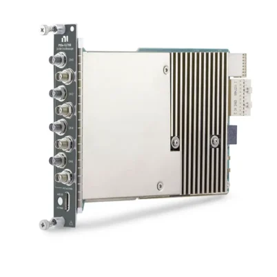
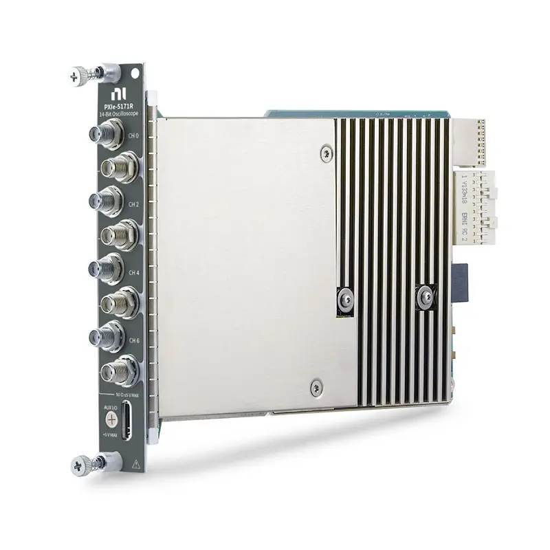
The PXIe-5171 is an 8-channel, 14-bit reconfigurable PXI oscilloscope designed for high-density waveform acquisition, automated testing and FPGA-based signal processing. It combines 250 MHz analog bandwidth, simultaneous sampling at up to 250 MS/s per channel and a user-programmable Xilinx Kintex-7 410T FPGA.
With eight simultaneously sampled analog inputs, 1.5 GB of onboard memory and advanced PXI synchronization, the PXIe-5171 is well suited for multichannel research, aerospace and defense testing, semiconductor validation, physics experiments and automated production systems.
Key Features of the PXIe-5171
- Eight simultaneously sampled analog input channels
- 250 MHz rated analog bandwidth
- 250 MS/s maximum real-time sample rate per channel
- 14-bit analog-to-digital resolution
- User-programmable Xilinx Kintex-7 410T FPGA
- 1.5 GB of onboard acquisition memory
- Five selectable input ranges from 0.2 Vpk-pk to 5 Vpk-pk
- 50 Ω analog input impedance
- AC and DC input coupling
- Selectable 100 MHz anti-alias filter
- Eight bidirectional programmable function interface lines
- Support for NI peer-to-peer data streaming
- NI-TClk multidevice synchronization
- PXI Express Gen 2 x8 interface
- Single-slot 3U PXI Express module
PXIe-5171 Technical Specifications
| Product Model | PXIe-5171 |
|---|---|
| Part Number | 783692-01 |
| Product Type | Reconfigurable PXI Oscilloscope |
| Bus Interface | PXI Express Gen 2 x8 |
| Analog Input Channels | 8, simultaneously sampled |
| Analog Bandwidth | 250 MHz rated |
| Full-Bandwidth −3 dB Point | 260 MHz on the 0.2 Vpk-pk range; 270 MHz on other ranges |
| Bandwidth-Limiting Filter | 100 MHz anti-alias filter |
| Maximum Sample Rate | 250 MS/s per channel |
| Real-Time Sample Rate Range | 3.815 kS/s to 250 MS/s |
| Resolution | 14 bits |
| Input Type | Referenced single-ended |
| Input Impedance | 50 Ω |
| Input Coupling | AC or DC |
| Full-Scale Input Ranges | 0.2 V, 0.4 V, 1 V, 2 V and 5 Vpk-pk |
| Maximum Input Overload | Absolute peak voltage of 5 V or less |
| Analog Connectors | SMA |
| Onboard Memory | 1.5 GB shared among enabled channels |
| FPGA | Xilinx Kintex-7 XC7K410T |
| Programmable Function Interface | 8 bidirectional PFI lines through the AUX I/O connector |
| Internal Timebase | 250 MHz |
| External Sample Clock Range | 150 MHz to 250 MHz |
| Trigger Types | Edge, window, hysteresis, digital, immediate and software |
| Operating Temperature | 0°C to 45°C |
| Warm-Up Time | 15 minutes |
| Calibration Interval | 2 years |
| Module Size | 3U, one-slot PXI Express module |
PXIe-5171 Part Number and Configuration
| Part Number | Channels | Bandwidth | Sample Rate | FPGA | Memory |
|---|---|---|---|---|---|
| 783692-01 | 8 | 250 MHz | 250 MS/s | Kintex-7 410T | 1.5 GB |
The PXIe-5171 is offered as a single primary hardware configuration. Verify the module part number when requesting a quotation, replacement unit or calibration service.
Eight Simultaneously Sampled Channels
All eight analog channels can be sampled simultaneously at up to 250 MS/s. This architecture preserves the timing relationships between signals and makes the module suitable for phase comparison, multichannel transient recording and synchronized device testing.
Multiple PXIe-5171 modules can be installed in the same PXI Express chassis when more than eight channels are required. NI-TClk can align sample clocks and triggers across supported modules.
250 MHz Bandwidth and 250 MS/s Sampling
The PXIe-5171 provides a rated analog bandwidth of 250 MHz. Its specified full-bandwidth −3 dB point is 260 MHz on the 0.2 Vpk-pk range and 270 MHz on the remaining input ranges.
A selectable 100 MHz anti-alias filter can reduce out-of-band noise when the full analog bandwidth is unnecessary. The real-time sampling rate can be reduced through decimation from 250 MS/s to support longer acquisitions and lower-frequency signals.
14-Bit Measurement Resolution
The 14-bit analog-to-digital converter provides greater amplitude resolution than conventional 8-bit oscilloscopes. This helps engineers observe smaller waveform changes, analyze signal distortion and characterize devices with demanding dynamic-range requirements.
Actual measurement performance also depends on the selected input range, signal frequency, grounding, cabling, source impedance and environmental noise.
Kintex-7 410T User-Programmable FPGA
The integrated Xilinx Kintex-7 XC7K410T FPGA enables custom processing directly on the oscilloscope. Engineers can develop FPGA functions for specialized triggering, inline signal processing, waveform reduction and deterministic data streaming.
| FPGA Slice Registers | 508,400 |
|---|---|
| FPGA Lookup Tables | 254,200 |
| DSP Slices | 1,540 |
| 18 Kb Block RAMs | 1,590 |
Some FPGA resources are reserved for instrument operation and software integration. Custom FPGA development requires compatible NI software and an appropriate LabVIEW FPGA development environment.
Input Ranges, Coupling and Impedance
The PXIe-5171 provides five full-scale input ranges: 0.2 Vpk-pk, 0.4 Vpk-pk, 1 Vpk-pk, 2 Vpk-pk and 5 Vpk-pk. Selecting the smallest suitable range improves utilization of the 14-bit converter.
Each channel provides AC or DC coupling and a fixed 50 Ω input impedance. Because the module does not provide a 1 MΩ input option, probes and signal sources must be selected for compatibility with a 50 Ω measurement path.
Signals exceeding an absolute peak voltage of 5 V can damage the input. Higher-voltage signals require suitable attenuation or an oscilloscope with a higher supported input range.
Onboard Memory and Data Streaming
The PXIe-5171 includes 1.5 GB of onboard memory shared among all enabled channels. Memory can be used for long records, multirecord acquisition and high-speed transient capture.
The PXI Express Gen 2 x8 interface supports high-throughput transfer to the system controller. Peer-to-peer streaming can also transfer data between compatible PXI Express modules without routing every sample through the host processor.
Triggering and Programmable I/O
Supported NI-SCOPE trigger types include edge, window, hysteresis, digital, immediate and software triggering. Trigger sources include the eight analog channels, PFI lines, PXI trigger lines and software commands.
The front-panel AUX I/O connector provides eight bidirectional PFI lines. These lines can be used for external triggering, event routing and interaction with custom FPGA logic.
Typical PXIe-5171 Applications
- High-density automated test systems
- Aerospace and defense signal acquisition
- Semiconductor characterization and validation
- Multichannel transient recording
- Physics and scientific research
- Ultrasonic and nondestructive testing
- Power electronics waveform analysis
- Radar and communications research
- Custom protocol and modulation analysis
- FPGA-based real-time signal processing
- Hardware-in-the-loop testing
- Production-line functional testing
Software Support
The PXIe-5171 can be operated as a conventional oscilloscope through the NI-SCOPE instrument driver. NI-SCOPE provides configuration, acquisition, triggering, calibration and data-transfer functions for supported programming environments.
- NI-SCOPE instrument driver
- InstrumentStudio interactive measurements
- NI Measurement & Automation Explorer
- LabVIEW
- LabWindows/CVI
- Measurement Studio
- Microsoft Visual C/C++
- .NET languages, including C# and VB.NET
- LabVIEW Instrument Design Libraries for Reconfigurable Oscilloscopes
- LabVIEW FPGA Module for custom FPGA development
PXI Express Chassis Integration
The PXIe-5171 requires a compatible PXI Express chassis and system controller. The module occupies one 3U PXI Express slot and uses a Gen 2 x8 bus interface.
For sustained high-speed operation, the chassis must provide sufficient cooling and data bandwidth. Use slot blockers and filler panels in unused slots, and follow the chassis airflow recommendations when operating the oscilloscope at high acquisition rates.
Browse compatible NI PXI modules and system components when configuring a complete measurement platform.
PXIe-5171 Troubleshooting
Why is the measured amplitude lower than expected?
Confirm that the signal source is designed to drive a 50 Ω load. An impedance mismatch can change the measured amplitude. Also check the selected input range, probe attenuation, coupling mode and cable condition.
Why does the signal appear bandwidth-limited?
Check whether the 100 MHz anti-alias filter is enabled. Disable the filter when the application requires the full 250 MHz bandwidth.
Why are long acquisitions limited?
The 1.5 GB onboard memory is shared among all enabled channels. Reduce the number of active channels, lower the sample rate or use continuous data streaming when longer acquisition periods are required.
Why is the FPGA compilation unsuccessful?
Verify that the installed LabVIEW, LabVIEW FPGA and Instrument Design Libraries versions support the PXIe-5171. Custom designs must also fit within the FPGA resources available after the instrument infrastructure is included.
Why do multiple modules show timing differences?
Use a shared reference clock, configure NI-TClk synchronization and perform self-calibration after the system reaches operating temperature. Identical acquisition settings should be used when minimizing module-to-module skew.
PXIe-5171 Comparison
| Model | Channels | Bandwidth | Sample Rate | Resolution | Primary Difference |
|---|---|---|---|---|---|
| PXIe-5171 | 8 | 250 MHz | 250 MS/s | 14-bit | Eight channels with a Kintex-7 410T FPGA |
| PXIe-5170 | 4 or 8 | 100 MHz | 250 MS/s | 14-bit | Lower-bandwidth Kintex-7 325T option |
| PXIe-5172 | 4 or 8 | 100 MHz | 250 MS/s | 14-bit | Offers 50 Ω and 1 MΩ inputs with wider voltage ranges |
| PXIe-5164 | 2 | 400 MHz | 1 GS/s | 14-bit | Higher sample rate and bandwidth with fewer channels |
| PXIe-5105 | 8 | 60 MHz | 60 MS/s | 12-bit | Conventional high-density oscilloscope without a user FPGA |
Recommended Related Products
- PXIe-5170 – Recommended when 100 MHz bandwidth is sufficient and a Kintex-7 325T FPGA meets the processing requirements.
- PXIe-5172 – Suitable for applications requiring selectable 50 Ω or 1 MΩ impedance and wider input-voltage ranges.
- PXIe-5164 – A two-channel alternative providing 400 MHz bandwidth and sampling rates up to 1 GS/s.
- PXIe-5105 – An eight-channel, 60 MHz option for conventional acquisition applications that do not require a programmable FPGA.
How to Select the Right PXI Oscilloscope
- Choose the PXIe-5171 when eight simultaneous channels and 250 MHz bandwidth are required.
- Choose the PXIe-5170 when 100 MHz bandwidth is adequate and project cost is a priority.
- Choose the PXIe-5172 for high-impedance measurements or signals requiring wider input ranges.
- Choose the PXIe-5164 when sample rate and bandwidth are more important than channel density.
- Choose the PXIe-5105 for lower-frequency eight-channel acquisition without custom FPGA processing.
Why Choose the PXIe-5171?
The PXIe-5171 combines eight simultaneous channels, 14-bit resolution, 250 MHz bandwidth and a large Kintex-7 FPGA in a single PXI Express slot. It is particularly valuable when a measurement system needs both high channel density and real-time processing close to the signal source.
Its modular PXI architecture also allows the oscilloscope to be integrated with waveform generators, digital instruments, switches, source measure units and other synchronized test hardware.
Frequently Asked Questions
What is the PXIe-5171?
The PXIe-5171 is an eight-channel, 14-bit reconfigurable PXI Express oscilloscope with 250 MHz bandwidth, 250 MS/s sampling and a Kintex-7 410T FPGA.
What is the part number for the PXIe-5171?
The standard NI part number is 783692-01.
Are all eight channels sampled simultaneously?
Yes. The PXIe-5171 provides simultaneous sampling on all eight analog input channels at rates up to 250 MS/s per channel.
Does the PXIe-5171 have a programmable FPGA?
Yes. It includes a user-programmable Xilinx Kintex-7 XC7K410T FPGA for custom acquisition, triggering, processing and streaming.
Does the PXIe-5171 support 1 MΩ input impedance?
No. Its analog inputs use a fixed 50 Ω impedance. Consider the PXIe-5172 or PXIe-5164 when a 1 MΩ input is required.
How much onboard memory is available?
The module includes 1.5 GB of onboard memory shared among all enabled channels.
Can multiple PXIe-5171 modules be synchronized?
Yes. Supported modules can be synchronized through the PXI backplane using NI-TClk, shared clocks and trigger routing.
Can the PXIe-5171 operate without a PXI Express chassis?
No. It requires a compatible PXI Express chassis, controller and software environment.
Request a Quote for the PXIe-5171
Contact us for current availability, lead time and project pricing for the PXIe-5171 Reconfigurable PXI Oscilloscope. We can also help verify compatible PXI Express chassis, controllers, cables, software and synchronized measurement modules for your application.















