








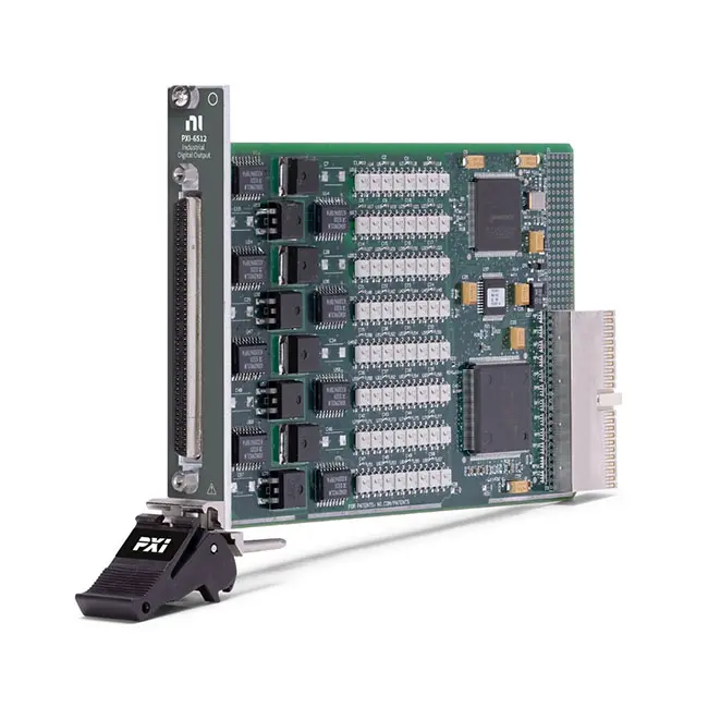
PXI-6512 64-Channel Bank-Isolated Sourcing Digital Output Module
The PXI-6512 is a 64-channel industrial digital output module designed for controlling external relays, indicators, valves, actuators and other industrial devices from a PXI automated test or control system. Its outputs are organized into eight optically isolated banks, with eight sourcing output lines in each bank.
The module supports external field supplies up to 30 VDC and provides as much as 350 mA from one active line in a port. Programmable power-up states and a digital I/O watchdog allow engineers to define predictable output behavior during system startup or if the computer application stops responding.
Key Features of the PXI-6512
- 64 industrial digital output channels
- Dedicated sourcing output architecture
- Eight isolated output banks
- Eight output lines per bank
- 30 VDC maximum switching voltage
- 350 mA maximum output current when one line in a port is active
- 75 mA per line when all eight lines in a port are active
- 30 VDC bank-to-bank and bank-to-bus isolation
- 80 µs typical output propagation delay
- Programmable power-up output states
- Digital I/O watchdog with configurable safe states
- Self-resetting fuse protection on each output port
- 100-pin keyed female SCSI front connector
- PXI hybrid-slot compatibility
- Single-slot 3U PXI module
- NI-DAQmx software support
PXI-6512 Technical Specifications
| Product Model | PXI-6512 |
|---|---|
| Part Number | 778969-01 |
| Product Type | Industrial bank-isolated digital output module |
| Total Digital Output Channels | 64 |
| Digital Input Channels | None |
| Output Direction | Sourcing |
| Number of Isolated Banks | 8 |
| Output Lines per Bank | 8 |
| Isolation Type | Bank-to-bank and bank-to-PXI-bus isolation |
| Common-Mode Isolation | 30 VDC |
| Maximum Switching Voltage | 30 VDC |
| Maximum Current, One Active Line per Port | 350 mA |
| Maximum Current, All Eight Lines Active | 75 mA per line |
| Typical Output Propagation Delay | 80 µs with a 100 Ω load |
| Default Power-On State | Logic 0, output open |
| Programmable Power-Up State | Logic 0 or logic 1 |
| Power-Up State Response Time | 400 ms |
| Overcurrent Protection | Self-resetting fuse on each output port |
| Data Transfers | Interrupts and programmed I/O |
| Front-Panel Connector | 100-pin keyed female SCSI connector |
| Bus Connector | PXI hybrid |
| Module Format | 3U, single-slot PXI module |
| Dimensions | Approximately 21 cm × 13 cm |
| Weight | Approximately 136 g |
| Typical +5 VDC Current | 250 mA |
| Typical +3.3 VDC Current | 300 mA |
| Operating Temperature | 0°C to 55°C |
| Operating Humidity | 10% to 90%, noncondensing |
| Storage Temperature | -20°C to 70°C |
| Software Support | NI-DAQmx |
PXI-6512 Part Number and Accessories
| Item | Part Number | Description |
|---|---|---|
| PXI-6512 | 778969-01 | 64-channel, 30 VDC, bank-isolated sourcing digital output module |
| SH100M-100M Flex Cable | 185095-01 | 1 m shielded 100-pin digital I/O cable assembly |
| R100M-50F-50F Cable | 182762-02 | 2 m ribbon cable converting one 100-pin connection to two 50-pin connectors |
| SCB-100A | 785024-01 | Shielded, noise-rejecting 100-pin screw-terminal connector block |
| CB-50 | 776164-90 | 50-pin I/O connector block with DIN-rail mounting |
| CB-50LP | 777101-01 | Low-cost unshielded 50-pin I/O connector block |
The recommended shielded connection uses the SH100M-100M Flex cable with the SCB-100A connector block. Shielded cables and accessories should be used to maintain the specified electromagnetic compatibility performance.
The R100M-50F-50F cable divides the module connection into two 50-pin connectors. Two CB-50 or CB-50LP blocks are required when this cable is used to access all output channels.
64 Industrial Digital Outputs
The PXI-6512 provides 64 dedicated output-only channels. This high channel count allows one module to control a large number of industrial devices from a single PXI chassis slot.
Typical loads include external relays, status indicators, low-current solenoids, valves, alarms and control inputs on programmable logic controllers or other industrial equipment.
Eight Bank-Isolated Output Groups
The 64 channels are divided into eight isolated ports or banks, each containing eight output lines. Every bank uses a shared external field supply and common connection.
The banks are electrically isolated from each other and from the PXI bus up to the specified 30 VDC common-mode isolation rating. Different banks can therefore operate from separate compatible field supplies or ground references.
Sourcing Output Architecture
The PXI-6512 uses sourcing outputs. When an output is activated, it supplies current from the external bank power connection through the selected output line to the connected load.
Sourcing outputs are commonly paired with sinking loads or PLC inputs whose return path is connected to the field-supply common. The PXI-6512 does not provide a sinking-output configuration.
For applications requiring current-sinking outputs, consider the PXI-6513 sinking digital output module.
External Field-Power Requirement
The module does not independently generate the voltage used to operate connected loads. Each output bank requires an appropriate user-provided external field supply.
The supply voltage must remain within the 30 VDC maximum switching rating. Confirm the supply polarity, load current, common connection and bank wiring before enabling the outputs.
30 VDC Output Operation
The PXI-6512 supports external output supplies and switched signals up to 30 VDC. This makes it suitable for common 12 V and 24 V industrial control systems.
Do not use the module to switch AC mains circuits or voltages above the specified limit. External interposing relays should be used when the final load operates at a higher voltage or current.
350 mA Single-Line Current Capability
One active output line in a port can supply as much as 350 mA. This rating applies when only one line in that eight-channel port carries the load current.
The 350 mA value must not be applied independently to all eight lines in the same port. Total current and thermal dissipation determine the allowable current when several outputs operate simultaneously.
Current Derating for Multiple Active Outputs
| Output Usage | Maximum Current per Active Line | Applicable Ambient Temperature |
|---|---|---|
| One active line per port | 350 mA | Up to 55°C |
| All eight lines active in a port | 75 mA per line | Up to 55°C |
For intermediate numbers of active channels, evaluate the port’s total current, ambient temperature, airflow, voltage, duty cycle and load behavior. Operation above the applicable rating may damage the module or trip its protection.
Self-Resetting Port Fuses
Each output port includes a self-resetting fuse for overcurrent protection. If excessive current causes a fuse to trip, the affected port may stop driving its connected outputs until the overload is removed and the protection device has recovered.
The fuse is an additional protective feature and should not replace properly sized external circuit protection. The system designer should limit the available fault current from the field supply.
Bank-to-Bank Isolation
The eight output banks provide 30 VDC common-mode isolation from one another and from the PXI bus. This helps prevent field wiring and ground differences from coupling directly into the controller.
Channels within the same bank are not individually isolated from one another because they share the bank power and common terminals. Select the PXI-6528 channel-to-channel isolated digital I/O module when every output requires its own isolated reference.
Programmable Power-Up States
The default power-on state is logic 0, with the output open. Software can program each output to power up in logic 0 or logic 1 after the module initializes.
This feature helps establish predictable actuator and fixture behavior while the operating system and test application are starting. The programmed state has a specified response time of approximately 400 ms.
Digital I/O Watchdog
The PXI-6512 includes a digital output watchdog that monitors whether the host application continues to operate correctly. If the application stops servicing the watchdog, the module can place its outputs into configurable expiration states.
Watchdog states can help turn off actuators, release fixture controls or activate an alarm after a computer or software failure. Safety-critical equipment should still use an independent safety-rated control system.
80 µs Typical Output Delay
Typical propagation delay is approximately 80 µs with a 100 Ω load. This response is appropriate for static industrial control and automated test switching.
The PXI-6512 is not intended for high-speed waveform generation or clocked digital-pattern applications. Select a hardware-timed digital module when precise high-frequency output timing is required.
Controlling External Relays
The sourcing outputs can energize compatible DC relay coils within the module’s voltage and current ratings. External relays allow the PXI-6512 to control higher-current or higher-voltage circuits while maintaining separation between the digital output module and final load.
Install a flyback diode or another suitable suppression device across each DC relay coil. Inductive voltage generated when the coil is switched off can damage the output circuitry.
Solenoid and Valve Control
The PXI-6512 can operate low-current solenoids and valves that remain within the applicable per-line and per-port current limits. Loads requiring more current should be driven through an external relay or power driver.
Check steady-state current, startup current and coil-release transients. A load with acceptable steady-state current can still exceed the module rating during initial energization.
Indicator and Alarm Control
The module can control LED indicators, low-current lamps, buzzers and alarm circuits in a production fixture or industrial test station.
Use external current limiting when it is not already included in the load. Verify that each device is compatible with the external field-supply voltage.
PLC Output Signal Simulation
The PXI-6512 can apply sourcing digital signals to compatible PLC inputs, industrial controllers and devices under test. This makes it useful for simulating field sensors or control commands during validation.
Confirm that the receiving input is designed for a sourcing signal and that its common connection provides the required current-return path.
Production Test Fixture Control
In production test systems, the PXI-6512 can control fixture clamps, pneumatic valves, power relays, indicators and other low-current devices. Its 64-channel density reduces the number of separate control modules required in a large fixture.
Programmable startup states and watchdog expiration states help return the fixture to a defined condition when the computer starts or an application error occurs.
Automotive Controller Testing
The module can simulate sourcing discrete outputs and control external devices in automotive electronic control-unit test systems. Separate banks can be assigned to different fixture sections or compatible voltage domains.
The PXI-6512 can be combined with analog measurement modules, CAN interfaces and fault insertion equipment for hardware-in-the-loop and electronic validation applications.
Aerospace and Industrial Validation
Aerospace and industrial test systems can use the module to operate relays, indicators and control inputs during automated qualification sequences.
The complete fixture must satisfy the required isolation, grounding, current limiting and safety requirements. The PXI-6512’s bank isolation should not be treated as channel-to-channel isolation within an individual bank.
NI-DAQmx Software Support
The PXI-6512 is controlled through the NI-DAQmx driver. NI-DAQmx provides functions for writing digital port or line values, configuring programmable startup states and managing watchdog behavior.
The module can be programmed through LabVIEW and compatible text-based development environments. NI Measurement & Automation Explorer can identify the device, assign its resource name and test output operation.
LabVIEW Real-Time Integration
The PXI-6512 can be used in compatible LabVIEW Real-Time PXI systems. A real-time controller can coordinate the outputs with data acquisition, communication, switching and test-sequence operations.
For deterministic control, include the module’s propagation delay, external relay response and load settling time in the real-time application design.
PXI Hybrid-Slot Compatibility
The PXI-6512 uses a PXI hybrid-compatible bus connector and occupies one chassis slot. It can be installed in a compatible PXI slot or PXI Express hybrid peripheral slot.
Before installation, confirm chassis compatibility, controller support, available cooling and the required NI-DAQmx software version.
Typical PXI-6512 Applications
- Industrial actuator control
- Production test fixture automation
- External relay control
- Solenoid and pneumatic-valve control
- PLC input simulation
- Status indicator control
- Alarm and annunciator operation
- Automotive ECU testing
- Aerospace controller validation
- Hardware-in-the-loop testing
- Environmental chamber automation
- Manufacturing-line control
- Industrial equipment sequencing
- High-channel-count static digital output
PXI-6512 Troubleshooting
The PXI-6512 is not detected in NI MAX
Confirm that the module is fully installed in a compatible PXI or PXI Express hybrid slot. Check chassis power, controller communication and NI-DAQmx installation, then restart the system and rescan the hardware.
An output does not supply voltage
Verify that the corresponding bank has a correctly connected external field supply. The PXI-6512 does not generate the load voltage independently.
The output logic is reversed from the expected operation
Confirm that the receiving device is compatible with a sourcing output. Check the load connection, field-supply common and active-state logic used by the application.
One output port suddenly turns off
The port’s self-resetting fuse may have tripped because of excessive current. Disconnect the loads, check for wiring shorts and confirm that the total port current remains within the applicable rating.
The module can drive one load but not eight loads
The 350 mA rating applies when only one line in a port is active. When all eight lines are active, the maximum rating is 75 mA per line.
An output works without the load but fails when connected
Measure the load’s startup and steady-state current. Confirm that the external supply can provide the required current and that the output does not exceed its single-line or total port rating.
The output state changes after an application failure
Review the watchdog timeout and expiration-state configuration. A configured watchdog intentionally changes outputs when the application fails to service it within the selected time.
The wrong outputs activate during system startup
Check the programmable power-up states in NI-DAQmx. Also verify the external hardware design because the outputs remain open in their default unconfigured power-on condition.
An inductive load damages the output
Install a flyback diode, snubber or suitable transient suppressor directly across the inductive load. Do not rely on the PXI-6512 output to absorb coil energy.
Some outputs cannot be controlled through the terminal blocks
If using the R100M-50F-50F cable, confirm that two CB-50 or CB-50LP connector blocks are installed. One 50-pin block does not provide access to all 64 outputs.
PXI-6512 Comparison with Similar Digital Output Modules
| Model | Primary Configuration | Best Suited For |
|---|---|---|
| PXI-6512 | 64 sourcing outputs, eight isolated banks, 30 VDC | High-density sourcing industrial control |
| PXI-6513 | 64 sinking outputs, eight isolated banks, 30 VDC | High-density sinking industrial control |
| PXI-6514 | 32 isolated inputs and 32 sourcing outputs | Combined industrial input monitoring and sourcing control |
| PXI-6515 | 32 isolated inputs and 32 sinking outputs | Combined input monitoring and sinking control |
| PXI-6528 | 24 inputs and 24 outputs with channel-to-channel isolation | Applications requiring independent isolation for every channel |
| PCI-6512 | 64 bank-isolated sourcing outputs | Desktop PCI-based industrial control systems |
PXI-6512 vs PXI-6513
The PXI-6512 provides 64 sourcing outputs, while the PXI-6513 provides 64 sinking outputs. Both organize their channels into eight isolated banks and support field voltages up to 30 VDC.
Choose the PXI-6512 for loads requiring current to be supplied from the output. Select the PXI-6513 when the load requires the output module to provide a current-return path to common.
PXI-6512 vs PXI-6514
The PXI-6512 dedicates all 64 channels to sourcing outputs. The PXI-6514 provides 32 industrial inputs and 32 sourcing outputs.
Select the PXI-6512 when maximum sourcing-output density is the main requirement. Choose the PXI-6514 when the test system must monitor field inputs and control sourcing outputs with one module.
PXI-6512 vs PXI-6528
The PXI-6512 provides 64 outputs organized into eight isolated banks. The PXI-6528 provides fewer outputs but offers channel-to-channel isolation and includes 24 isolated digital inputs.
Choose the PXI-6512 for high-density sourcing control with shared bank references. Select the PXI-6528 when every channel requires an independent isolated reference or the system needs both inputs and outputs.
Recommended Related Products
- PXI-6513 64-Channel Sinking Digital Output Module
- PXI-6514 Industrial Sourcing Digital I/O Module
- PXI-6515 Industrial Sinking Digital I/O Module
- PXI-6528 Channel-to-Channel Isolated Digital I/O Module
- PCI-6512 64-Channel Sourcing Digital Output Device
- View More NI PXI and PXI Express Modules
Selecting the Right Industrial Digital Output Module
Choose the PXI-6512 when the application requires 64 sourcing outputs, 30 VDC operation and eight isolated banks. It is well suited for controlling many low-current industrial loads from one PXI slot.
Select the PXI-6513 for sinking outputs, the PXI-6514 for a combination of inputs and sourcing outputs or the PXI-6528 when channel-to-channel isolation is required.
Before ordering, confirm output direction, field voltage, load current, number of simultaneously active outputs, bank isolation and terminal-block requirements.
Why Choose the PXI-6512?
- Provides 64 dedicated sourcing outputs
- Organizes the outputs into eight isolated banks
- Supports common 12 V and 24 V industrial systems
- Provides up to 350 mA on one active line per port
- Includes programmable power-up states
- Provides watchdog-controlled safe output states
- Includes self-resetting overcurrent protection
- Uses a high-density 100-pin connector
- Integrates with NI-DAQmx and LabVIEW
- Occupies one compatible PXI chassis slot
Frequently Asked Questions
What is the PXI-6512?
The PXI-6512 is a 64-channel bank-isolated sourcing digital output module for industrial PXI control and automated test systems.
What is the PXI-6512 part number?
The standard NI part number for the PXI-6512 is 778969-01.
How many output channels does it provide?
The module provides 64 dedicated digital output channels divided into eight banks of eight lines.
Does the PXI-6512 provide digital inputs?
No. All 64 channels are dedicated sourcing outputs.
What is the maximum output voltage?
The maximum switching voltage is 30 VDC.
What is the maximum output current?
One active line in a port can supply up to 350 mA. If all eight lines in a port are active, the maximum is 75 mA per line.
Does the PXI-6512 provide sourcing or sinking outputs?
It provides sourcing outputs. Choose the PXI-6513 when sinking outputs are required.
Are all channels independently isolated?
No. The module uses bank isolation. Eight channels in each bank share the same field power and common connections.
What is the isolation rating?
The specified common-mode isolation is 30 VDC from bank to bank and from each bank to the PXI bus.
Does it require an external power supply?
Yes. A compatible external field supply is required to provide the voltage and current delivered through each output bank.
What is the default output state?
The default power-on state is logic 0 with the output open. Power-up states can be programmed to logic 0 or logic 1.
Does the PXI-6512 include a watchdog?
Yes. The digital I/O watchdog can place outputs into configured safe states after a computer or application failure.
Does it include overcurrent protection?
Yes. Each output port has a self-resetting fuse, although external current limiting and load protection are still recommended.
Which connector does the PXI-6512 use?
The front panel uses a 100-pin keyed female SCSI connector.
Which cable and terminal block are recommended?
The shielded SH100M-100M Flex cable and SCB-100A terminal block provide the recommended connection method.
Which software controls the module?
The PXI-6512 is controlled through NI-DAQmx and can be integrated with LabVIEW, LabVIEW Real-Time and compatible text-based programming environments.
Request a Quote for the PXI-6512
Contact us for current availability, lead time and project pricing for the PXI-6512 64-Channel Bank-Isolated Sourcing Digital Output Module. We can also help identify compatible SH100 cables, SCB-100A or CB-50 terminal blocks, PXI chassis and related sinking or mixed industrial digital I/O modules.















