






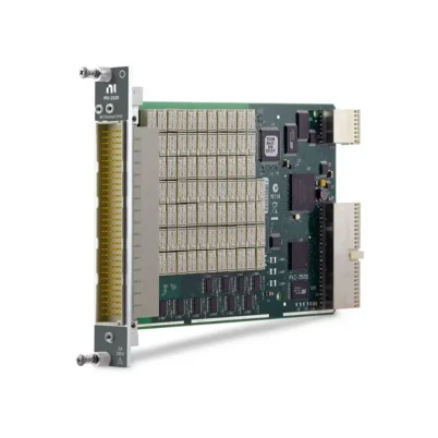

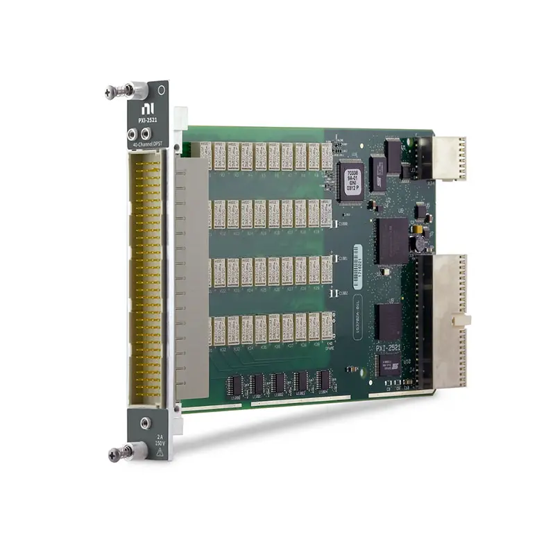
PXI-2521 40-Channel 2 A DPST PXI Relay Module
The PXI-2521 is a general-purpose PXI relay module containing 40 independently controlled double-pole single-throw relays. Each DPST relay switches two related conductors simultaneously, making the module suitable for paired-signal routing, load control and automated test equipment.
The PXI-2521 supports signals up to 150 V, current up to 2 A and switching power up to 60 W or 62.5 VA per channel. Its nonlatching electromechanical relays provide low path resistance, low thermal offset and physical contact isolation for automated validation and production test systems.
Key Features of the PXI-2521
- 40 independent DPST relay channels
- 80 simultaneously switched poles
- Nonlatching electromechanical armature relays
- 150 V maximum switching voltage
- 2 A maximum switching and carry current per channel
- 60 W or 62.5 VA maximum switching power per channel
- 25 MHz typical two-wire bandwidth
- 30 MHz typical one-wire path bandwidth
- Less than 0.5 Ω initial DC path resistance
- 12 µV typical thermal EMF
- 145 cycles/s scan rate
- 1 ms typical relay operate time
- All 40 relays can be driven simultaneously
- Onboard relay-count tracking
- Field-replaceable relays
- PXI hardware trigger support
- 160-position male DIN connector
- PXI hybrid-slot compatibility
- NI-SWITCH and NI Switch Executive support
PXI-2521 Technical Specifications
| Product Model | PXI-2521 |
|---|---|
| Part Number | 778572-21 |
| Product Type | General-purpose PXI relay module |
| Number of Relay Channels | 40 |
| Relay Configuration | DPST, double-pole single-throw |
| Number of Switched Poles | 80 |
| Default Contact State | Normally open |
| Relay Operation | Nonlatching |
| Maximum Switching Voltage | 150 V channel-to-channel or channel-to-ground |
| Measurement Category | CAT I signal circuits |
| Maximum Switching Current | 2 A per channel |
| Maximum Carry Current | 2 A per channel |
| Simultaneous Channels at Maximum Current | 40 at up to 55°C |
| Maximum Switching Power | 60 W or 62.5 VA per channel |
| Minimum Switching Conditions | 20 mV at 1 mA |
| Initial DC Path Resistance | Less than 0.5 Ω |
| End-of-Life Path Resistance | 1 Ω or greater |
| Typical Thermal EMF | 12 µV at 23°C |
| Typical One-Wire Bandwidth | 30 MHz with 50 Ω termination |
| Typical Two-Wire Bandwidth | 25 MHz with 50 Ω termination |
| Scan Rate | 145 cycles/s |
| Typical Relay Operate Time | 1 ms |
| Maximum Relay Operate Time | 3.4 ms |
| Simultaneous Drive Limit | 40 relays |
| Mechanical Relay Life | 1 × 10⁸ cycles |
| Electrical Relay Life at 30 V, 1 A | 5 × 10⁵ cycles, resistive load |
| Electrical Relay Life at 30 V, 2 A | 1 × 10⁵ cycles, resistive load |
| Relay Type | Electromechanical, nonlatching |
| Relay Contact Material | Gold-covered palladium-ruthenium |
| Input Trigger Sources | PXI trigger lines 0 through 7 |
| Minimum Input Trigger Pulse Width | 150 ns |
| Output Trigger Destinations | PXI trigger lines 0 through 7 |
| Output Trigger Pulse Width | Programmable from 1 µs to 62 µs |
| I/O Connector | 160-position male DIN 41612 |
| Bus Interface | PXI hybrid |
| PXI Power Requirement | 7 W at 5 V and 2.5 W at 3.3 V |
| Module Format | 3U, one-slot PXI/cPCI module |
| Dimensions | 21.6 × 2.0 × 13.0 cm |
| Weight | 182 g |
| Operating Temperature | 0°C to 55°C |
| Storage Temperature | −20°C to 70°C |
| Relative Humidity | 5% to 85%, noncondensing |
| Maximum Altitude | 2,000 m |
| Software Support | NI-SWITCH and NI Switch Executive |
PXI-2521 Part Number and Accessories
| Item | Part Number | Description |
|---|---|---|
| PXI-2521 | 778572-21 | 40-channel, 2 A, DPST PXI relay module |
| 160-Pin DIN to Bare-Wire Cable | 782417-01 | 1 m cable for custom test fixtures and direct signal wiring |
| 160-Pin DIN to 160-Pin DIN Cable | 782417-02 | 1 m cable for compatible DIN-to-DIN switch connections |
| 160-Pin DIN to Four 50-Pin D-Sub Cable | 782417-03 | Breakout cable for connecting the module to four compatible terminal blocks |
| 160-Pin DIN to Bare-Wire Cable | 781090-03 | Alternative compatible bare-wire connection cable |
| TBX-50B Terminal Block | 782866-01 | 50-pin screw-terminal block for external field wiring |
The PXI-2521 uses a 160-position DIN front-panel connector. Select the cable and terminal-block arrangement according to the fixture wiring, number of relay poles, cable length, voltage rating and expected current.
40-Channel DPST Relay Architecture
The PXI-2521 contains 40 independently controlled double-pole single-throw relays. Each relay opens or closes two electrically separate poles at the same time.
This paired operation is useful when both conductors of a signal, load or power circuit must be connected or disconnected together. The module provides 80 switched poles organized into 40 synchronized pairs.
Understanding DPST Relays
A DPST relay has two poles and one switched position. When the relay is open, both signal paths are disconnected. When the relay closes, both paths establish their respective connections simultaneously.
Unlike a DPDT relay, a DPST relay does not select between normally open and normally closed destinations. It performs paired on/off switching without changeover routing.
Paired Signal Switching
The two poles of each PXI-2521 channel can switch positive and negative signal conductors, line and return connections or two related control circuits.
Switching both conductors can help isolate a device under test from the connected source or measurement instrument. The isolation requirements of the complete system must still be checked against the module and fixture ratings.
Independent Software Control
Every DPST relay can be controlled independently through software. Test programs can close selected relays, open individual channels or disconnect all routes according to the automated sequence.
Multiple relay channels can operate simultaneously. The PXI-2521 supports driving all 40 relays, subject to its electrical ratings and chassis operating conditions.
150 V Switching Capability
The PXI-2521 supports signals up to 150 V between channels and up to 150 V from a channel to ground. The module is rated for Measurement Category I signal circuits.
It must not be connected directly to building mains or used for Measurement Category II, III or IV circuits. When hazardous voltage is present on any relay terminal, safety-low-voltage signals must not be connected to other relay terminals.
2 A Switching and Carry Current
Each relay channel supports switching and carry current up to 2 A. The module can operate all 40 channels at maximum current at ambient temperatures up to 55°C when all other specifications are satisfied.
The two poles, external cable, terminal block and fixture wiring must all be rated for the expected current. Connector resistance and conductor size should be considered for continuously energized loads.
60 W and 62.5 VA Switching Power
The maximum switching power is 60 W per channel for DC loads and 62.5 VA for applicable AC loads. Voltage, current and switching-power limits apply simultaneously.
The full 2 A current rating cannot be switched at 150 V because the resulting power would exceed 60 W. Calculate the voltage-current product for the actual load before operating the relay.
Low DC Path Resistance
Initial DC path resistance is specified at less than 0.5 Ω. Low path resistance reduces voltage drop and power dissipation when routing current through the relay.
The complete system path also includes cable, connector, terminal-block and fixture resistance. These external components may contribute more resistance than the module itself.
Low Thermal Offset
The PXI-2521 provides a typical thermal EMF of 12 µV at 23°C. This helps limit offset error when switching low-level DC voltage and measurement signals.
For sensitive measurements, minimize temperature gradients across the connectors and cable, separate low-level wiring from load-current paths and allow the system to settle after switching.
25 MHz Two-Wire Bandwidth
The paired two-wire signal path provides typical bandwidth of 25 MHz with 50 Ω termination. An individual one-wire path can provide typical bandwidth up to 30 MHz.
Actual system bandwidth depends on cable length, source and load impedance, external fixture design and the number of simultaneously energized signal paths.
Fast Automated Scanning
The PXI-2521 supports scanning at up to 145 cycles per second. Typical relay operate time is 1 ms, with a specified maximum of 3.4 ms.
Complete test throughput also depends on relay settling time, measurement aperture, software execution, trigger configuration and stabilization of the device under test.
Nonlatching Electromechanical Relays
The module uses nonlatching electromechanical armature relays. The relays return to their default open state when chassis power is removed.
This behavior can provide a predictable disconnected condition after shutdown. Test-system designers should verify that the power-off state is appropriate for the connected sources, loads and device under test.
Relay Life and Maintenance
The expected mechanical relay life is 100 million cycles. Electrical life depends on the switched voltage, current and load characteristics.
NI specifies approximately 500,000 operations for a 30 V, 1 A resistive load and approximately 100,000 operations for a 30 V, 2 A resistive load.
The PXI-2521 relays are field replaceable when serviced according to the appropriate NI instructions. Relay-count data can help maintenance teams identify heavily used channels.
Onboard Relay-Count Tracking
The module records the number of times each relay operates. These counts can be retrieved programmatically to support predictive maintenance and identify channels with unusually high usage.
When the fixture design allows it, frequently used signal paths can be reassigned to other relay channels to distribute wear more evenly.
PXI Hardware Triggering
The PXI-2521 accepts input triggers from PXI trigger lines 0 through 7. The specified minimum trigger pulse width is 150 ns with digital filtering enabled.
Output triggers can be routed to PXI trigger lines 0 through 7 with a programmable pulse width from 1 µs to 62 µs. This supports synchronized switching with other PXI instruments.
Typical PXI-2521 Applications
- Automated test equipment
- Paired signal connection and disconnection
- Two-conductor load switching
- Production functional testing
- Heater control
- Light and lamp control
- Fan control
- Power and return-path switching
- Device-under-test isolation
- Reliability and environmental testing
- Test-fixture automation
- Laboratory equipment control
Automated Test Equipment
The PXI-2521 can connect or disconnect paired signal paths during an automated test sequence. This removes the need for manual cable changes and allows one test station to evaluate several device operating states.
Software can coordinate the relays with digital multimeters, power supplies, data acquisition modules and other PXI instruments.
Heater, Light and Fan Control
The module’s voltage and current capacity makes it suitable for controlling appropriately rated heaters, lights and fans. The two poles can switch both conductors or operate two related load connections simultaneously.
Motors, relays, fans and other inductive loads can generate high-voltage transients when disconnected. Suitable flyback diodes, snubbers or other suppression components may be required.
Device-Under-Test Isolation
A DPST relay can disconnect both sides of a device or circuit from the test system. This can provide better isolation than opening only one conductor.
The relay is not a safety disconnect unless the complete system has been designed and certified for that purpose. Review voltage category, insulation, connector spacing and protective enclosure requirements.
Production Functional Testing
Production systems can use the PXI-2521 to switch loads, power paths and measurement connections according to the product being tested. All 40 relay channels can be controlled independently within a single PXI module.
Relay-count tracking allows production engineers to identify high-use paths and schedule maintenance before relay wear causes unexpected downtime.
NI-SWITCH Software Support
The PXI-2521 is controlled through the NI-SWITCH instrument driver. NI-SWITCH provides functions for initializing the module, opening and closing relay channels, creating scan lists, configuring triggers and reading relay counts.
The driver supports LabVIEW, LabWindows/CVI and compatible text-based programming environments.
NI Switch Executive Integration
NI Switch Executive allows developers to assign descriptive aliases to physical relay channels and create named routes or route groups.
This makes automated test programs easier to read and maintain, especially when the system contains multiple relay modules, instruments and fixture connections.
PXI Hybrid-Slot Integration
The PXI-2521 uses a PXI hybrid bus interface and occupies one 3U chassis slot. It can operate with other PXI instruments such as digital multimeters, power supplies, data acquisition modules and digitizers.
Before installation, verify the chassis slot type, power, airflow, controller compatibility and installed NI-SWITCH version. Turn off the chassis before installing or removing the module.
PXI-2521 Troubleshooting
The PXI-2521 is not detected in NI MAX
Confirm that the module is fully installed in a compatible PXI hybrid slot. Check chassis power, controller communication and NI-SWITCH installation, then rescan the system in NI Measurement & Automation Explorer.
One DPST channel does not close
Verify that the correct relay channel is addressed in software. Check both poles at the front-panel connector and inspect the cable, terminal block and external fixture wiring.
Only one pole appears to switch
Check cable continuity and connector pin assignments for both poles. A wiring error or damaged external conductor can make a correctly operating DPST relay appear to switch only one path.
The signal path has excessive resistance
Inspect the cable, connector, terminal block and fixture wiring. Compare the complete measured resistance with the module’s initial path specification and review relay usage for the affected channel.
A load causes relay-contact problems
Check for capacitive inrush current or inductive voltage transients. Confirm that the voltage, current and switching power remain within specification and add appropriate external protection.
The scan rate is lower than expected
Review relay settling time, software execution, trigger timing and measurement aperture. The specified scan rate does not include every delay in a completed test sequence.
The module reports inconsistent relay operation
Use NI-SWITCH diagnostics and relay-count information to identify the affected channel. Check the external cable before determining that a field-replaceable relay requires service.
The module becomes unusually warm
Stop the test and check the number of active relays, load current, connector resistance and chassis airflow. Confirm that the module remains within its electrical and environmental ratings.
PXI-2521 Comparison with Similar Relay Modules
| Model | Relay Configuration | Best Suited For |
|---|---|---|
| PXI-2520 | 80 independent SPST relays | High-density single-pole on/off switching |
| PXI-2521 | 40 independent DPST relays | Paired two-pole on/off switching |
| PXI-2522 | 40 independent SPDT relays | Single-pole changeover routing |
| PXI-2523 | 26 independent DPDT relays | Paired two-pole changeover routing |
| PXI-2569 | 100 independent SPST relays | Maximum-density general-purpose relay switching |
PXI-2521 vs PXI-2520
The PXI-2521 provides 40 DPST relays, while the PXI-2520 provides 80 independent SPST relays. Both provide 80 poles, but the PXI-2521 organizes them into 40 synchronized two-pole channels.
Choose the PXI-2521 when two conductors must always switch together. Choose the PXI-2520 when every pole must be controlled independently.
PXI-2521 vs PXI-2522
The PXI-2521 uses 40 DPST relays for two-pole on/off switching. The PXI-2522 uses SPDT relays that connect one common terminal to one of two throw positions.
Select the PXI-2521 for paired connection and disconnection. Select the PXI-2522 when the application requires single-pole changeover or source selection.
PXI-2521 vs PXI-2523
The PXI-2521 provides 40 DPST relays, while the PXI-2523 provides 26 DPDT relays. Both switch two poles simultaneously, but the PXI-2523 adds changeover between two throw positions.
Choose the PXI-2521 for a higher number of two-pole on/off channels. Choose the PXI-2523 when each channel must select between normally open and normally closed paths.
Recommended Related Products
- PXI-2520 80-Channel SPST Relay Module
- PXI-2522 40-Channel SPDT Relay Module
- PXI-2523 26-Channel DPDT Relay Module
- PXI-2569 100-Channel SPST Relay Module
- PXIe-4080 Digital Multimeter
- View More NI PXI and PXI Express Modules
Selecting the Right PXI Relay Module
Choose the PXI-2521 when the application requires 40 independently controlled two-pole on/off channels, 2 A switching, 150 V capability and nonlatching operation. It is well suited to paired signals, load control and circuit isolation in automated test systems.
Select the PXI-2520 when individual pole control is more important. Choose the PXI-2522 for single-pole changeover or the PXI-2523 when two-pole changeover routing is required.
Why Choose the PXI-2521?
- Provides 40 independently controlled DPST relays
- Switches 80 poles in synchronized pairs
- Supports signals up to 150 V and 2 A
- Allows all 40 channels to operate simultaneously
- Provides low path resistance and thermal offset
- Offers 25 MHz typical two-wire bandwidth
- Uses field-replaceable nonlatching relays
- Includes onboard relay-count tracking
- Supports deterministic hardware triggering
- Integrates with NI-SWITCH and NI Switch Executive
Frequently Asked Questions
What is the PXI-2521?
The PXI-2521 is a 40-channel DPST PXI relay module for paired signal switching, load control and automated test equipment.
What does DPST mean?
DPST means double-pole single-throw. Each relay opens or closes two separate electrical paths simultaneously.
How many relays does the PXI-2521 provide?
The module provides 40 independently controlled DPST relays, equivalent to 80 switched poles.
What is the maximum switching voltage?
The maximum switching voltage is 150 V between channels or between a channel and ground for CAT I signal circuits.
What is the maximum switching current?
The maximum switching or carry current is 2 A per relay channel.
What is the maximum switching power?
The maximum switching power is 60 W or 62.5 VA per channel. Voltage, current and power limits must all be observed.
What is the bandwidth of the PXI-2521?
The typical two-wire bandwidth is 25 MHz. An individual one-wire path provides typical bandwidth up to 30 MHz.
Are the relays latching?
No. The PXI-2521 uses nonlatching relays that return to their default open state when module power is removed.
Can all 40 relays operate simultaneously?
Yes. The simultaneous drive limit is 40 relays, subject to the module’s electrical and environmental ratings.
Are the PXI-2521 relays replaceable?
Yes. The relays are field replaceable when serviced according to the applicable NI procedure.
Which cables are compatible with the PXI-2521?
Compatible options include the 782417-01 bare-wire cable, 782417-02 DIN-to-DIN cable and 782417-03 DIN-to-four-D-Sub breakout cable.
What is the PXI-2521 part number?
The standard NI part number is 778572-21.
Request a Quote for the PXI-2521
Contact us for current availability, lead time and project pricing for the PXI-2521 40-Channel 2 A DPST PXI Relay Module. We can also help identify compatible 160-pin DIN cables, TBX-50B terminal blocks, PXI chassis and related NI relay modules for your automated test system.















