




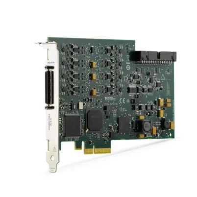
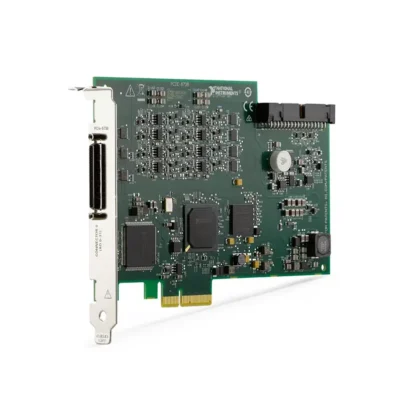
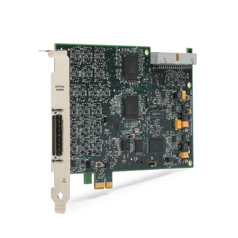
PCIe-6535B 32-Channel High-Speed Digital I/O Device
The PCIe-6535B is a 32-channel high-speed digital I/O device designed for pattern generation, digital waveform acquisition, display testing, image-sensor interfacing and custom protocol emulation. It supports hardware-timed operation at clock rates up to 10 MHz and maximum throughput of 40 MB/s.
Each of the 32 single-ended digital lines can be independently configured as an input or output. This per-channel direction control allows one device to simultaneously generate command data, acquire response signals and exchange bidirectional information with a device under test.
The PCIe-6535B supports selectable 2.5 V and 3.3 V output logic families and compatibility with 5 V TTL inputs. Continuous data streaming through the PCI Express bus enables long-duration digital acquisition and generation without relying only on limited onboard waveform memory.
Key Features of the PCIe-6535B
- 32 bidirectional digital I/O channels
- Per-channel input or output direction control
- 10 MHz maximum hardware clock rate
- 40 MB/s maximum digital throughput
- 100 ns minimum digital update interval
- 2.5 V and 3.3 V selectable output levels
- 5 V TTL-compatible digital inputs
- Up to 32 mA digital output-current drive
- Continuous PCI Express data streaming
- Pattern generation and waveform acquisition
- Change-detection and handshaking support
- Hardware triggering and external clocking
- 68-pin VHDCI front connector
- NI-DAQmx software support
- NI Digital Waveform Editor compatibility
PCIe-6535B Technical Specifications
| Product Model | PCIe-6535B |
|---|---|
| Part Number | 782629-01 |
| Product Type | High-speed digital I/O device |
| Bus Interface | PCI Express |
| Digital I/O Channels | 32 bidirectional channels |
| Direction Control | Individually programmable per channel |
| Maximum Clock Rate | 10 MHz |
| Maximum Throughput | 40 MB/s |
| Minimum Update Interval | 100 ns |
| Output Logic Families | 2.5 V and 3.3 V |
| Input Compatibility | 2.5 V, 3.3 V and 5 V TTL |
| Maximum Channel Current Drive | 32 mA |
| Input Impedance | 50 kΩ |
| Signaling Type | Single-ended |
| Front Connector | 68-pin VHDCI |
| Operating Temperature | 0°C to 45°C |
| Software Driver | NI-DAQmx |
PCIe-6535B Part Number and Accessories
| Item | Part Number | Description |
|---|---|---|
| PCIe-6535B | 782629-01 | 32-channel, 10 MHz PCI Express digital I/O device |
| SHC68-C68-D4 Cable | 196275-01 | 1 m shielded single-ended digital I/O cable |
| SHC68-C68-D4 Cable | 781293-01 | 2 m shielded single-ended digital I/O cable |
| C68-C68-D4 Cable | 195949-01 | 1 m unshielded 68-pin VHDCI digital cable |
| SCB-68A | 782536-01 | Shielded screw-terminal connection block |
| TBX-68 | 777141-01 | 68-pin DIN-rail terminal block |
| CB-68LP | 777145-01 | Low-cost unshielded connector block |
32 Independently Configurable Digital Lines
Each PCIe-6535B digital line can be configured independently as an input or output. This provides more flexibility than devices that require an entire port to share one direction.
For example, one group of lines can generate a parallel command word while another group acquires status or response data from the DUT during the same test operation.
10 MHz Hardware-Timed Operation
The device supports digital updates every 100 ns, corresponding to a maximum hardware clock rate of 10 MHz. Hardware timing provides repeatable edge placement without requiring the host application to issue an individual software command for every state transition.
The actual operating rate may be limited by cable length, fixture loading, voltage level, signal integrity and DUT timing requirements.
Continuous PCI Express Streaming
The PCI Express bus allows waveform data to stream continuously between host memory and the digital I/O engine. This supports long digital patterns and extended acquisitions that would otherwise exceed local device memory.
The computer, memory subsystem and software architecture must maintain the required transfer rate to prevent output underflow or acquisition overflow.
Selectable Voltage Levels
The PCIe-6535B supports selectable output levels for 2.5 V and 3.3 V logic and can interface with compatible 5 V TTL input signals. Confirm the DUT voltage family before enabling generation.
The device is not intended for direct connection to 24 V industrial signals. External isolation and level conversion are required for industrial voltage interfaces.
Handshaking and Protocol Emulation
Handshaking signals allow the device and DUT to coordinate data transfers. Rather than transferring data only at a fixed rate, the two devices can indicate when information is ready and when it has been accepted.
This functionality supports custom parallel interfaces, memory-style buses and lower-speed communication protocols that do not require a dedicated standardized interface controller.
PCIe-6535B Applications
- Digital pattern generation
- Digital waveform acquisition
- LCD and display-panel testing
- Image-sensor interfacing
- Custom digital protocol emulation
- Parallel-bus functional testing
- Change-detection monitoring
- Memory-device testing
- Production electronics testing
- Embedded-system validation
- Automated test equipment
Display and Image-Sensor Testing
The PCIe-6535B can generate control patterns and acquire parallel digital data used by compatible displays and imaging devices. Clock, data and handshaking signals can be coordinated within one hardware-timed task.
Custom Digital Interfaces
Engineers can create digital patterns representing proprietary command and response sequences. Per-line direction control is particularly useful for protocols containing both input and output signals.
PCIe-6535B Installation Workflow
Step 1: Confirm Computer Compatibility
Verify that the computer provides an available PCI Express slot and supports the required NI-DAQmx version.
Step 2: Install the Device
Power down the computer, follow ESD-safe handling procedures and secure the PCIe-6535B in the slot.
Step 3: Connect the VHDCI Cable
Use an appropriate shielded digital I/O cable and terminal accessory. Keep high-speed lines short and provide reliable return paths.
Step 4: Configure Logic Levels
Select an output voltage family compatible with the DUT before enabling the outputs.
Step 5: Configure Timing and Direction
Assign each line as input or output, then configure the sample clock, start trigger, active edge and data-transfer mode.
Step 6: Verify at a Low Clock Rate
Begin testing at a reduced clock frequency and verify the logic levels and timing before increasing the rate to 10 MHz.
PCIe-6535B Troubleshooting
The device is not detected
Check PCI Express seating, NI-DAQmx installation and operating-system compatibility.
Generated logic levels are incorrect
Verify the selected voltage family and measure the signal with the DUT disconnected. Check output loading and external pull resistors.
Data becomes unreliable at higher clock rates
Shorten the cable, improve termination and grounding, reduce capacitive loading and verify the DUT setup-and-hold requirements.
A continuous generation task stops
Review NI-DAQmx errors for buffer underflow. Increase the buffer or write data earlier and in larger blocks.
Acquired data is shifted by one clock cycle
Confirm the active sampling edge and the timing relationship between the DUT data and clock.
PCIe-6535B Comparison
| Model | Channels | Maximum Clock | Maximum Throughput |
|---|---|---|---|
| PCIe-6535B | 32 | 10 MHz | 40 MB/s |
| PCIe-6536B | 32 | 25 MHz | 100 MB/s |
| PCIe-6537B | 32 | 50 MHz | 200 MB/s |
| PCI-6534 | 32 | Legacy configuration | PCI platform |
Choose the PCIe-6535B for digital applications requiring up to 10 MHz operation. Select the PCIe-6536B when additional clock speed and streaming throughput are required.
PCIe-6535B Frequently Asked Questions
How many digital channels does the PCIe-6535B provide?
It provides 32 independently configurable bidirectional digital I/O channels.
What is its maximum clock rate?
The maximum hardware clock rate is 10 MHz.
Can each channel have a different direction?
Yes. Direction is independently programmable for each digital line.
Can it communicate directly with 24 V devices?
No. External voltage conversion and isolation are required for 24 V industrial signals.
What is the PCIe-6535B part number?
The standard part number is 782629-01.
Recommended Related Products
- PCIe-6536B 25 MHz Digital I/O Device
- PCIe-6537B 50 MHz Digital I/O Device
- PCI-6534 High-Speed Digital I/O Device
- PXIe-6548 Digital Waveform Instrument
Request a Quote for the PCIe-6535B
Contact us for current availability and project pricing for the PCIe-6535B high-speed digital I/O device. We can also help identify compatible VHDCI cables and terminal accessories.















