






Quick Answer: Choose a CompactDAQ system by defining the signals and sensors first, then selecting compatible C Series modules, a chassis with the right slot count and host connection, and a computer or embedded target that can process and store the complete workload. Verify sample rate, accuracy, isolation, signal conditioning, synchronization, aggregate bandwidth, operating environment, software support, accessories, calibration, and future expansion. The best CompactDAQ system is the configuration that meets the complete measurement requirement without unnecessary channels, bandwidth, or complexity.
How to Choose a CompactDAQ System: 10-Step Process
1. Define the SignalsList every sensor, input, output, range, bandwidth, channel count, and isolation requirement.
2. Select C Series ModulesChoose modules from measurement performance, signal conditioning, sampling architecture, and connector requirements.
3. Choose the ChassisCompare slot count, USB or Ethernet connectivity, timing resources, bandwidth, environment, and expansion.
4. Verify the Complete SystemConfirm software, drivers, accessories, power, storage, synchronization, calibration, and lifecycle support.
What Is a CompactDAQ System?
A CompactDAQ system is a modular data acquisition platform built from a chassis, compatible C Series I/O modules, a host computer or embedded target, software, terminal accessories, sensors, cables, and power components.
The chassis provides module slots, communication, power, timing, and synchronization resources. C Series modules provide the electrical interface and signal conditioning for voltage, current, temperature, strain, vibration, sound, digital I/O, counters, relays, and industrial communication.
CompactDAQ is commonly used for:
- Environmental and temperature monitoring
- Structural and strain measurements
- Sound and vibration testing
- Machine condition monitoring
- Automotive and transportation testing
- Energy and power measurements
- Laboratory data acquisition
- Portable and distributed measurements
Choose the System in the Correct Order
A common mistake is choosing a chassis first and then searching for modules that fit it. The correct order begins with the signals because the required modules determine slot count, sampling mode, data throughput, timing, power, and software requirements.
Recommended selection order:
- Define the measurement objectives.
- Create a complete signal and channel list.
- Select suitable C Series modules.
- Calculate slots and aggregate data rate.
- Define triggering and synchronization.
- Choose USB, Ethernet, or an embedded architecture.
- Select the CompactDAQ chassis.
- Verify the computer, processor, memory, and storage.
- Confirm software, drivers, accessories, and calibration.
- Test the most demanding configuration.
Step 1: Define Every Signal and Sensor
Begin with a channel list that describes what the system must measure or control. Avoid vague entries such as “analog input.” Each line should state the real electrical and sensor requirements.
| Requirement | Questions to Answer |
|---|---|
| Signal type | Voltage, current, thermocouple, RTD, strain, IEPE, digital, counter, relay, or communication? |
| Channel count | How many channels operate simultaneously, and how many are reserved for expansion? |
| Signal range | What are the normal and worst-case minimum and maximum levels? |
| Bandwidth | What is the highest frequency or fastest physical event that must be captured? |
| Accuracy | What total uncertainty is acceptable across sensor, module, wiring, and calibration? |
| Isolation | Is channel, bank, or channel-to-earth isolation required? |
| Excitation | Does the sensor require bridge, IEPE, current, or voltage excitation? |
| Direction | Is the channel an input, output, bidirectional line, or switching function? |
Selection rule: Use the worst-case signal and environmental conditions, not only the normal operating value. Include startup transients, common-mode voltage, sensor tolerance, cable noise, and expected temperature changes.
Step 2: Select the C Series Modules
Choose modules that match the signal, not modules with the highest headline sample rate or resolution. A technically suitable module must meet the complete electrical, timing, conditioning, connector, and software requirement.
Voltage and Current Modules
Compare input or output range, resolution, absolute accuracy, input impedance, coupling, bandwidth, isolation, overvoltage protection, and sampling architecture. For current loops, verify whether the module includes an internal shunt and whether external loop power is required.
Temperature Modules
For thermocouples, check sensor type, cold-junction compensation, channel isolation, open-thermocouple detection, input range, and conversion rate. For RTDs, verify sensor type, two-, three-, or four-wire connection, excitation, lead compensation, and resistance range.
Strain and Bridge Modules
Verify quarter-, half-, or full-bridge support, bridge completion, excitation voltage, remote sense, shunt calibration, gauge resistance, sensitivity, and maximum sample rate.
Sound and Vibration Modules
Check IEPE excitation, compliance voltage, AC or DC coupling, analog bandwidth, anti-alias filtering, dynamic range, simultaneous sampling, and digital-filter group delay.
Digital, Counter, and Relay Modules
Compare logic level, sourcing or sinking behavior, current, external supply, isolation, hardware timing, counter support, switching speed, contact rating, relay life, and protection for inductive loads.
Explore available C Series modules by signal type before finalizing the chassis.
Step 3: Check Simultaneous and Multiplexed Sampling
Simultaneous-sampling modules use separate converters so their channels can capture the same event at the same instant. Multiplexed modules share a converter across several channels and acquire enabled channels sequentially.
| Architecture | Best Suited For | Key Limitation |
|---|---|---|
| Simultaneous sampling | Phase, vibration, acoustic, transient, and power measurements | Often higher cost and data rate |
| Multiplexed sampling | Temperature, slow voltage, general monitoring, and high channel density | Channel-to-channel acquisition delay |
| Delta-sigma conversion | Low-noise dynamic measurements with integrated filtering | Digital-filter delay must be considered |
| On-demand I/O | Slow control, status, relay, and user-commanded operations | Software timing is not deterministic |
Check whether the published sample rate is per channel, per module, or aggregate. Enabling additional channels can reduce the rate available to each channel on a multiplexed module.
Step 4: Calculate the Required Sample Rate
The sample rate must be high enough to represent the measured signal and leave practical margin for filtering and analysis. A rate chosen only from the expected event duration may miss high-frequency content or transients.
Consider:
- Highest signal frequency
- Required time resolution
- Anti-alias filtering
- Transient duration
- Frequency-domain analysis
- Filter group delay
- Storage volume and test duration
For slow sensors such as thermocouples, very high sample rates may add data without improving useful information. For vibration, sound, switching transients, and dynamic power, sampling and analog bandwidth require much closer review.
Step 5: Calculate Aggregate Data Throughput
Every module may be individually compatible while the full system exceeds chassis, USB, Ethernet, processor, memory, or storage performance.
Estimate raw input throughput using:
Active channels × samples per second × bytes per sample
Then add output streams and operating margin for:
- Protocol and driver overhead
- Timestamps and scaling
- Buffering
- Analysis and visualization
- File-format overhead
- Network transfer
- Future channel expansion
Use sustained performance: Storage peak speed and interface headline bandwidth are not guaranteed continuous application throughput. Test the complete system for the intended duration.
Step 6: Define Timing and Synchronization
Decide whether channels only need to begin at approximately the same time or whether they require a shared hardware trigger, common sample clock, phase alignment, or synchronized timestamps.
Questions to Define
- What is the maximum acceptable start skew?
- Must channels share the same sample clock?
- How much clock drift is acceptable over the test duration?
- Are multiple modules or chassis involved?
- Is input-to-output latency important?
- What timestamp accuracy is required?
- Must the system synchronize with external equipment?
A common start trigger does not automatically eliminate drift between independent clocks. Also account for multiplexing, analog paths, digital-filter group delay, cable length, and sensor response.
Step 7: Choose USB, Ethernet, or Embedded Architecture
| Architecture | Choose It When | Main Considerations |
|---|---|---|
| USB CompactDAQ | The chassis is near a laptop or workstation and portability is important | Cable distance, host port, hubs, power management, and sustained bandwidth |
| Ethernet CompactDAQ | The chassis must be near remote sensors or distributed around equipment | IP addressing, switches, firewall, network load, timing support, and recovery |
| Embedded or real-time | Autonomous startup, local processing, deterministic execution, or FPGA access is required | Target software, deployment, storage, recovery, and programming architecture |
Choose USB for Simplicity and Portability
USB is a strong choice for laboratory measurements, portable testing, troubleshooting, and systems positioned close to a computer. Use a supported host port and cable, and avoid assuming every hub or docking station can sustain the workload.
Choose Ethernet for Distance and Distribution
Ethernet allows the chassis to be placed closer to sensors, reducing long analog cable runs. It also supports distributed measurement architectures, but network discovery, security, traffic, switches, and timing must be planned.
Choose Embedded Execution for Autonomous Operation
If the system must start after power loss, continue without a host PC, perform local logging, or execute deterministic logic, evaluate a compatible embedded, real-time, or programmable architecture.
Step 8: Choose the CompactDAQ Chassis
After selecting the modules and architecture, choose a chassis with sufficient slots, throughput, timing resources, environmental capability, power support, and expansion capacity.
Chassis Selection Checklist
- Number of usable C Series module slots
- USB, Ethernet, or embedded connection
- Compatibility with every planned module
- Aggregate data throughput
- Clock, trigger, and synchronization features
- Operating temperature, shock, and vibration
- Power input and maximum module load
- Mounting, enclosure, and cable access
- Driver, firmware, and operating-system support
- Spare slots for future expansion
Read CompactDAQ Chassis FAQ and CompactDAQ Chassis Compatibility before finalizing the chassis.
Step 9: Select the Computer and Storage
The host must receive data, run the driver and application, display results, perform analysis, and save files without causing buffer overflow.
Evaluate:
- Processor core count and single-core performance
- Available memory for waveform buffers and analysis
- USB or Ethernet controller performance
- Sustained storage write speed
- Storage capacity for the complete test duration
- Network speed for remote logging or databases
- Operating-system lifecycle and security policy
- Backup and recovery procedures
Separate acquisition, processing, visualization, and file writing into appropriate buffers or queues. A graph that refreshes too frequently can reduce acquisition performance even when the hardware is correctly selected.
Step 10: Verify Software and Driver Compatibility
Create a compatibility matrix before purchasing or upgrading hardware.
| Software Layer | What to Confirm |
|---|---|
| Operating system | Version, edition, processor architecture, and vendor support |
| Device driver | Support for the chassis, every C Series module, timing mode, and API |
| Development environment | Compatible version, bitness, modules, toolkits, and deployment runtime |
| Firmware | Required chassis and module firmware levels |
| Real-time target | Target software, deployment tools, startup behavior, and remote access |
| Application | Channel configuration, scaling, error handling, logging, and recovery |
Avoid uncontrolled operating-system or driver upgrades on validated systems. Preserve software installers, configuration exports, source code, firmware records, and a known-good system image.
Select the Correct Signal Conditioning
Many C Series modules include sensor-specific conditioning, which is one of the main advantages of CompactDAQ. Depending on the module, integrated functions can include:
- Thermocouple cold-junction compensation
- Bridge excitation and completion
- IEPE excitation
- Channel or bank isolation
- Anti-alias filtering
- Current input shunts
- Industrial digital thresholds
External conditioning may still be required for unusual sensors, hazardous voltages, high common-mode signals, intrinsic safety, specialized excitation, or strong electromagnetic interference.
Choose the Correct Terminal Blocks and Cables
A complete system order must include the accessories required to connect the modules to the sensors and device under test.
- Terminal blocks and mating connectors
- Backshells and strain relief
- Shielded or sensor-specific cable
- Thermocouple extension wire
- Bridge completion and excitation accessories
- External power supplies
- Mounting or enclosure hardware
- Network switches and Ethernet cables
Connector type can influence shielding, cold-junction compensation, installation time, serviceability, and measurement quality. Never assume that accessories are included with the chassis or module.
Consider the Operating Environment
Review the most restrictive environmental specification among the chassis, modules, terminal blocks, cables, power supply, computer, and enclosure.
- Operating and storage temperature
- Humidity and condensation
- Shock and vibration
- Altitude
- Dust and moisture
- Electromagnetic interference
- Hazardous-location requirements
- Mounting orientation and ventilation
Outdoor installations: A rugged chassis is not automatically weatherproof. A suitable enclosure may be required to control rain, dust, condensation, sunlight, corrosion, and temperature.
Plan Calibration and Measurement Uncertainty
Accuracy should be evaluated as a complete uncertainty budget, not only from ADC resolution. Include:
- Sensor accuracy and drift
- Module range accuracy and noise
- Temperature coefficients
- Excitation and lead-wire errors
- Terminal and connector effects
- Calibration uncertainty
- Environmental variation
- Software scaling and compensation
Define calibration intervals, traceability, downtime, spare modules, and whether the system requires field verification or factory calibration.
CompactDAQ vs PXI: Which Platform Is Better?
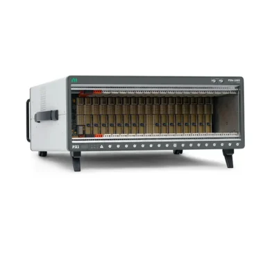
CompactDAQ is usually the better choice for portable, distributed, and sensor-focused data acquisition with integrated signal conditioning. PXI or PXI Express is usually better when the application requires several modular instruments, high sustained throughput, RF test, centralized switching, low-latency transfers, or advanced multi-instrument synchronization.
| Application Requirement | Typical Starting Point |
|---|---|
| Portable temperature, strain, or vibration acquisition | CompactDAQ |
| Distributed sensors around a machine or structure | Ethernet CompactDAQ |
| Mixed RF, digitizer, generator, DMM, and switching system | PXI/PXIe |
| High-throughput automated production test | PXI/PXIe |
| Slow remote sensors plus fast centralized instruments | Hybrid CompactDAQ and PXI |
See CompactDAQ vs PXI for a complete platform comparison.
Common CompactDAQ Selection Mistakes
- Choosing the chassis before selecting the modules
- Assuming every C Series module works in every chassis
- Confusing resolution with usable accuracy
- Ignoring simultaneous versus multiplexed sampling
- Using sample rate without checking analog bandwidth
- Assuming a common start trigger prevents clock drift
- Ignoring aggregate data rate and sustained storage speed
- Forgetting terminal blocks, cables, connectors, and external supplies
- Using a desktop operating system for deterministic control
- Ignoring calibration, lifecycle, spares, and software compatibility
Buying a Used CompactDAQ System
Used hardware can reduce cost for laboratory systems, mature installations, expansion, and spares. Confirm compatibility and functional condition before purchasing.
- Exact model, part number, revision, and serial-number condition
- Chassis-to-module and software compatibility
- Included power supplies, cables, terminal blocks, and accessories
- Condition of slots, connectors, latches, and housing
- Power-on, communication, and module-detection results
- Operation of every chassis slot
- Sustained acquisition with representative modules
- Calibration status of measurement modules
- Return period, warranty, repair, and replacement options
CompactDAQ System Buying Checklist
Confirm every item before placing the order:
- All signals, sensors, ranges, and channel counts are documented.
- Each C Series module meets the electrical and measurement requirements.
- Sampling architecture, rate, bandwidth, and filter delay are suitable.
- The chassis supports every module and required timing mode.
- There are sufficient slots and reasonable expansion capacity.
- USB, Ethernet, or embedded architecture fits the deployment.
- Aggregate data rate and storage requirements are calculated.
- Trigger, synchronization, and timestamp performance are verified.
- The computer, processor, memory, and storage can handle the workload.
- Operating system, driver, firmware, and application versions are compatible.
- Terminal blocks, connectors, cables, power supplies, and mounting are included.
- Environment, calibration, warranty, lifecycle, and spare units are planned.
Final Recommendation
Choose a CompactDAQ system from the measurement requirements outward. Start with the sensors and signals, select the correct C Series modules, calculate their slots and data rate, and then choose a compatible chassis, connection method, computer, software stack, and accessories.
For important or high-channel-count systems, build a representative proof of concept using the fastest channel, highest simultaneous load, longest cable, most difficult synchronization path, noisiest environment, and intended software version. This reveals compatibility, throughput, timing, grounding, and storage problems before the full system is purchased.
Continue Your CompactDAQ Research
Explore CompactDAQ systems and C Series modules at PXI Source. Continue with CompactDAQ Chassis FAQ, CompactDAQ Chassis Compatibility, and CompactDAQ vs PXI.
Explore CompactDAQ systems and C Series modules at PXI Source. Continue with CompactDAQ Chassis FAQ, CompactDAQ Chassis Compatibility, and CompactDAQ vs PXI.
Categories
Latest Articles
Products on Sale


Need Help Choosing a Product?
Contact our sales team for product selection, pricing, availability and lead-time information.
sales@pxisource.com