






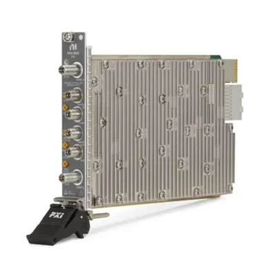
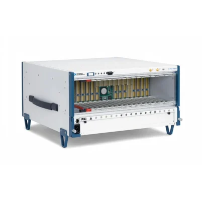
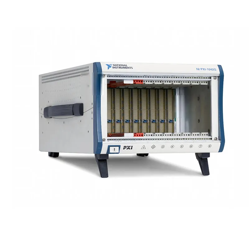
PXI-1042Q Quiet 8-Slot Universal AC PXI Chassis
The NI PXI-1042Q is a quiet, eight-slot PXI chassis designed for automated test, laboratory measurement, data acquisition and instrumentation systems. It combines a high-performance PXI backplane, universal AC power supply and temperature-controlled forced-air cooling in a compact benchtop or rack-mountable enclosure.
The chassis provides one system controller slot and seven peripheral slots for compatible 3U PXI and CompactPCI modules. Its low-noise cooling system can operate at a sound-pressure level as low as 43.4 dBA in AUTO fan mode at 25°C ambient temperature, making the PXI-1042Q particularly suitable for offices, laboratories and benchtop environments.
The PXI-1042Q provides the standard PXI timing resources required for synchronized measurement systems, including a low-jitter 10 MHz reference clock, eight PXI trigger lines, a PXI star trigger and local-bus connections. Rear-panel 10 MHz clock input and output connectors support synchronization with other instruments or chassis.
Key Features of the PXI-1042Q
- Eight-slot PXI chassis
- One system controller slot
- Seven PXI peripheral slots
- Compatible with 3U PXI and CompactPCI modules
- 132 MB/s maximum shared PXI backplane bandwidth
- Quiet operation for office and laboratory environments
- 43.4 dBA sound-pressure level in AUTO mode at 25°C
- AUTO and HIGH fan-speed settings
- 25 W cooling capacity per slot
- Two filtered 51 cfm system fans
- Temperature-controlled fan operation
- Universal 100 VAC to 240 VAC power input
- Removable high-performance power-supply shuttle
- Short-circuit, overload and overvoltage protection
- Built-in 10 MHz PXI reference clock
- Rear-panel 10 MHz reference clock input and output
- PXI trigger bus and star trigger support
- Remote power inhibit and voltage monitoring
- Front-panel power and fault indication
- Optional front and rear rack-mount kits
PXI-1042Q Technical Specifications
| Product Model | PXI-1042Q |
|---|---|
| Part Number | 778636-02 |
| Product Type | Quiet universal AC PXI chassis |
| Total Slots | 8 |
| System Controller Slots | 1 |
| Peripheral Slots | 7 |
| Module Format | 3U PXI and CompactPCI |
| PXI Backplane Type | PCI-based PXI backplane |
| Maximum System Bandwidth | 132 MB/s shared |
| Slot Cooling Capacity | 25 W per slot |
| System Fans | 2 × 51 cfm filtered fans |
| Fan Modes | AUTO and HIGH |
| AUTO-Mode Sound Pressure | 43.4 dBA at 25°C ambient |
| HIGH-Mode Sound Pressure | 52.9 dBA |
| AUTO-Mode Sound Power | 52.2 dBA at 25°C ambient |
| HIGH-Mode Sound Power | 62.4 dBA |
| Operating Temperature | 0°C to 40°C |
| AC Input Voltage | 100 VAC to 240 VAC |
| AC Input Frequency | 50 Hz to 60 Hz |
| Input Current Rating | 8 A |
| Input Overcurrent Protection | 10 A resettable circuit breaker |
| Power-Supply Efficiency | 70% typical |
| +3.3 V DC Capacity | 20 A |
| +5 V DC Capacity | 29 A |
| +12 V Peripheral-Slot Capacity | 3.5 A |
| +12 V System-Slot Capacity | 0.5 A |
| -12 V DC Capacity | 2 A |
| Internal Reference Clock | 10 MHz |
| Reference Clock Accuracy | ±25 ppm |
| Reference Clock Jitter | Less than 5 ps |
| Reference Clock Slot-to-Slot Skew | 250 ps maximum |
| PXI Trigger Bus | PXI trigger lines 0 through 7 |
| PXI Star Trigger | Supported |
| External Clock Connections | Rear-panel 10 MHz IN and OUT BNC connectors |
| Remote Monitoring Connection | Rear-panel 9-pin D-Sub |
| Dimensions | 177 mm × 271.3 mm × 396.5 mm |
| Dimensions in Inches | 6.97 in. × 10.68 in. × 15.61 in. |
| Weight | Approximately 8.4 kg or 18.6 lb |
PXI-1042Q Part Number and Accessories
| Item | Part Number | Description |
|---|---|---|
| PXI-1042Q | 778636-02 | Quiet eight-slot universal AC PXI chassis |
| PXI-1042Q Chassis Assembly | 191043 series | Internal assembly number; revision suffix depends on manufacturing revision |
| Front Rack-Mount Kit | Revision dependent | Mounts the front of the chassis in a compatible 19-inch equipment rack |
| Rear Rack-Mount Kit | Revision dependent | Provides additional chassis support in a rack installation |
| PXI-1042Q Power-Supply Shuttle | Chassis specific | Replacement power supply and fan assembly for the PXI-1042Q |
| PXI Slot Blockers | Configuration dependent | Improve airflow through populated module slots |
| EMC Filler Panels | Configuration dependent | Cover unused slots and maintain cooling and EMC performance |
| PXI-8250 System Monitor | Configuration dependent | Optional system-monitor module installed in slot 8 |
The PXI-1042 and PXI-1042Q use different AC power-supply shuttles. Their replacement shuttles are not interchangeable. Confirm the exact chassis model and assembly revision before ordering a replacement power unit.
Eight-Slot PXI Architecture
The PXI-1042Q contains eight total slots. Slot 1 is reserved for the system controller or compatible remote-control interface, while slots 2 through 8 accept compatible PXI and CompactPCI peripheral modules.
A system can use an embedded PXI controller for self-contained operation or a suitable MXI interface for control from an external computer. The selected controller must support the operating system, software and bandwidth required by the installed instruments.
The seven peripheral slots can accommodate instruments such as data acquisition modules, digitizers, digital multimeters, waveform generators, RF instruments, communication interfaces and switching modules.
PXI and CompactPCI Module Compatibility
The PXI-1042Q accepts compatible 3U PXI and CompactPCI modules. PXI extends CompactPCI by adding instrumentation-specific timing, triggering, environmental and software requirements.
The chassis is based on the original PCI-based PXI architecture. It does not provide native PCI Express data lanes and should not be treated as a PXI Express chassis. PXIe-only modules require a compatible PXI Express or hybrid chassis.
Before installation, confirm that each module uses a compatible PXI or CompactPCI connector and does not require PXI Express signaling.
132 MB/s Shared PXI Bandwidth
The PCI-based PXI backplane provides a theoretical maximum system bandwidth of 132 MB/s shared among the controller and installed modules.
This bandwidth is suitable for many switching, DMM, control, industrial communication and moderate-speed data acquisition applications. The practical sustained rate depends on the controller, module, driver and number of devices transferring data.
High-speed digitizers and waveform instruments may generate more data than the shared backplane can continuously transfer. Calculate the combined throughput requirements before selecting the chassis for a streaming application.
Quiet 43.4 dBA Operation
The Q designation identifies the quiet version of the PXI-1042 chassis family. In AUTO fan mode at 25°C ambient temperature, the PXI-1042Q achieves a sound-pressure level of approximately 43.4 dBA when measured at the operator position according to ISO 7779.
This low acoustic output makes the chassis suitable for office desks, research laboratories, teaching facilities and benchtop systems where continuous fan noise can be disruptive.
Sound level varies with ambient temperature, system loading, filter condition and fan mode. When the chassis requires additional cooling, its fan speed and acoustic output can increase.
AUTO and HIGH Fan Modes
A rear-panel selector provides AUTO and HIGH cooling modes. In AUTO mode, a temperature-sensing circuit adjusts fan speed according to the incoming-air temperature.
HIGH mode operates the fans at maximum speed and is recommended when maximum thermal margin is more important than acoustic noise. HIGH mode is particularly useful with high-power modules, restricted rack ventilation or elevated ambient temperatures.
The published HIGH-mode sound-pressure level is approximately 52.9 dBA. Although louder than AUTO mode, it provides the chassis’ maximum airflow.
25 W Per-Slot Cooling Capacity
The PXI-1042Q provides up to 25 W of cooling capacity for each module slot. Two filtered 51 cfm system fans create positive-pressure forced-air circulation through the chassis.
Air enters through the lower portion of the module area and travels upward from the P1 connector region toward P2. Filler panels and slot blockers help direct airflow through installed modules instead of allowing it to bypass empty slots.
Do not operate the chassis with unnecessary gaps in the front panel. Open slots can reduce cooling effectiveness, disturb airflow and compromise electromagnetic compatibility.
Filtered Forced-Air Cooling
The cooling system uses replaceable or serviceable filters to reduce the entry of dust and debris. Dirty filters restrict airflow and can increase module temperature, fan speed and acoustic noise.
Inspection frequency depends on the environment. Laboratories with airborne dust, production debris or textile fibers may require more frequent cleaning than controlled office spaces.
Keep the front and rear ventilation openings clear. Allow adequate space around the chassis so heated exhaust air is not drawn back into the intake.
Universal AC Power Input
The PXI-1042Q accepts universal AC input from 100 VAC to 240 VAC at 50 Hz or 60 Hz. Automatic voltage and frequency ranging allows the chassis to be used in different regions with the correct approved power cord.
The AC input current rating is 8 A, and a resettable 10 A circuit breaker provides input overcurrent protection. The chassis does not rely on a user-replaceable AC input fuse for routine overload recovery.
The AC power cord serves as the primary mains disconnect. Install the chassis so the power connector remains accessible.
High-Output DC Power Rails
The power supply delivers the +3.3 V, +5 V, +12 V and -12 V rails required by PXI and CompactPCI modules. At the PXI-1042Q operating-temperature rating, the available current includes 20 A on +3.3 V and 29 A on +5 V.
The peripheral-slot +12 V capacity is 3.5 A, with an additional 0.5 A specified for the system slot. The -12 V rail provides up to 2 A.
When configuring a fully populated chassis, total the power consumption on each rail rather than considering only overall wattage. A configuration can overload one voltage rail even when its total power appears acceptable.
Power-Supply Protection
All DC outputs include protection against short-circuit and overload conditions with automatic recovery. Overvoltage protection clamps the +3.3 V and +5 V outputs above their nominal values.
The front-panel power-switch LED can indicate a power-supply error. If a fault occurs, shut down the chassis and remove recently installed modules before attempting further diagnosis.
Repeated power faults may indicate an overloaded rail, a shorted module, an incorrectly installed card or a failing power-supply shuttle.
Removable Power-Supply Shuttle
The PXI-1042Q integrates the power supply and cooling fans into a removable rear shuttle. This modular design allows the main service assembly to be replaced without dismantling the backplane and card cage.
The specified mean time to repair for replacing the power-supply shuttle is less than five minutes when proper service procedures are followed.
The chassis must be powered down and disconnected from AC power before the shuttle is removed. Replacement should only be performed by qualified personnel following ESD and electrical-safety precautions.
PXI 10 MHz Reference Clock
The backplane distributes a 10 MHz reference clock to the PXI peripheral slots through matched-length traces. Modules can use this common timebase to derive sample clocks and coordinate timing operations.
The internal reference clock has an accuracy of approximately ±25 ppm, jitter below 5 ps and maximum slot-to-slot skew of 250 ps.
Using a shared timebase improves long-term coordination between instruments compared with allowing every module to operate from an unrelated oscillator.
External 10 MHz Clock Input
A rear-panel BNC input allows the chassis to use a compatible external 10 MHz reference signal. When a valid external clock is detected, it overrides the chassis’ internal reference source.
This feature is useful when the PXI-1042Q must synchronize with another chassis, a laboratory frequency standard or external test equipment.
The external signal must meet the specified frequency, amplitude and impedance requirements. An unsuitable reference can prevent correct backplane timing.
10 MHz Clock Output
The rear-panel clock output provides a buffered version of the chassis 10 MHz reference. It can be used as part of a synchronized system when connected to compatible timing equipment.
The output is not simply a general-purpose TTL clock connection. Use appropriate 50 Ω cabling and verify the electrical requirements of the receiving device.
PXI Trigger Bus
Eight PXI trigger lines run across the backplane and allow compatible modules to exchange digital trigger and timing signals. These lines can coordinate acquisition, signal generation and switching events without routing every connection through the front panel.
Trigger-line ownership must be managed by the application. Two modules should not drive incompatible signals onto the same trigger line.
PXI Star Trigger
The PXI star trigger uses dedicated point-to-point connections between the system timing slot and peripheral slots. Matched trace lengths reduce propagation differences between destinations.
A compatible timing module installed in slot 2 can distribute precise triggers to the other peripheral slots. This is useful for synchronizing digitizers, DAQ devices and waveform generators.
PXI Local Bus
The PXI local bus provides connections between adjacent peripheral slots. Compatible modules can use these lines for analog or digital signals that do not need to travel through external front-panel cables.
Local-bus behavior is module dependent. Confirm the signal assignment and electrical compatibility before installing adjacent modules that use these connections.
PXI-6653 Timing Integration
An NI PXI-6653 timing and synchronization module can be installed in the system timing slot to improve clock accuracy and coordinate the PXI-1042Q with additional measurement systems.
With a suitable timing module and reference, the 10 MHz system clock can achieve substantially greater accuracy than the chassis’ internal oscillator alone.
The timing module can also route triggers and reference clocks between the PXI backplane and external equipment.
Remote Power Inhibit and Voltage Monitoring
A rear-panel 9-pin D-Sub connector provides remote power-inhibit control and access to chassis voltage-monitoring signals. This allows the PXI-1042Q to be incorporated into centralized test-rack power control and monitoring systems.
Remote-control wiring must follow the chassis pinout. Do not connect arbitrary external voltages to the monitoring connector.
The interface can be used with appropriate supervisory hardware to detect rail problems or place the chassis into a controlled standby state.
Front-Panel Power and Fault Indicator
The front-panel power switch contains an LED that indicates chassis power and selected fault conditions. A steady green indication normally means the chassis is powered and operating normally.
A flashing red or abnormal indication can identify a power-supply voltage problem. Stop the test and investigate the installed modules, power rails and power-supply shuttle before continuing.
PXI-8250 System Monitoring
The optional PXI-8250 system monitor can be installed in slot 8 of the PXI-1042Q. It monitors chassis power rails and provides additional system-status and alarm functions.
The PXI-8250 must be installed in the rightmost slot. It is not intended for an arbitrary peripheral slot.
When slot 8 is assigned to system monitoring, six peripheral slots remain available for measurement and control modules.
Embedded PXI Controller Compatibility
An embedded PXI controller can be installed in the system slot to create a self-contained measurement platform. The controller provides the processor, memory, storage, networking and operating-system environment.
Verify mechanical compatibility, power demand, operating-temperature requirements and software support when selecting an embedded controller for this legacy chassis.
Older controllers may require legacy operating systems, while newer controllers may require a PXI Express chassis and cannot be installed in the PXI-1042Q.
Remote PC Control
The chassis can also be controlled from an external desktop or industrial computer using a compatible MXI interface. A remote architecture allows the host computer to be located separately from the measurement hardware.
A complete MXI system requires a host-side interface, a compatible PXI controller module and the correct cable. MXI generations and cable families are not automatically interchangeable.
Always verify host BIOS, operating-system and driver compatibility before assembling a remote-control system from legacy components.
Benchtop Operation
Adjustable front feet allow the PXI-1042Q to be tilted for improved visibility and access when used on a laboratory bench. Rubber feet help stabilize the chassis and protect the work surface.
The quiet fan system is particularly valuable when the chassis operates close to engineers, researchers or students for extended periods.
Maintain clear ventilation space even when the chassis is tilted. Do not place papers, cables or other equipment against the cooling openings.
Rack-Mount Installation
Optional front and rear rack-mount kits allow the chassis to be installed in a compatible 19-inch equipment rack. Rear support is recommended for systems exposed to transportation, vibration or frequent servicing.
Allow sufficient rear clearance for the power cord, cooling exhaust, reference clock cables and remote-monitor connector.
A rack containing several heat-producing instruments must provide adequate ventilation so the chassis intake remains within its 0°C to 40°C operating range.
Typical PXI-1042Q Applications
- Benchtop automated test systems
- Quiet laboratory measurement systems
- Production functional testing
- Electronic device validation
- Data acquisition and monitoring
- Digital multimeter and switch systems
- Audio and vibration measurements
- Automotive electronics testing
- Aerospace and defense validation
- Industrial communication testing
- Research and educational laboratories
- Rack-mounted instrumentation systems
- Multimodule synchronized acquisition
- Maintenance of existing PXI test stations
Automated Functional Testing
The PXI-1042Q can house a combination of DMMs, switch modules, data acquisition devices, waveform generators and communication interfaces. Test software can coordinate these instruments to apply stimulus and evaluate DUT responses.
The chassis’ timing resources allow measurements and switching events to be synchronized more consistently than independently connected benchtop instruments.
Data Acquisition Systems
Compatible PXI DAQ and digitizer modules can acquire voltage, current, temperature, vibration and other sensor signals. The required signal conditioning depends on the installed module and sensor type.
When several modules stream data simultaneously, ensure that their combined sustained throughput remains within the shared PCI backplane and controller limits.
Switching and DMM Systems
The PXI-1042Q is well suited to automated switching and digital multimeter applications that benefit from low bus latency but do not require modern PXI Express streaming bandwidth.
A PXI switch can route multiple DUT points to a DMM or measurement module, reducing instrument count and automating large test sequences.
Audio and Noise-Sensitive Laboratories
The reduced acoustic output of the PXI-1042Q is useful in audio laboratories and other environments where fan noise can interfere with personnel or acoustic measurements.
The chassis should still be physically isolated from sensitive microphones when the lowest possible measurement noise floor is required. Mechanical vibration and airborne fan noise depend on placement and operating mode.
PXI-1042Q Installation Workflow
Step 1: Inspect the Chassis
Check the chassis, power-supply shuttle, connector pins, air filters and enclosure for shipping or storage damage. Do not power a unit with visible electrical or mechanical damage.
Step 2: Select the Installation Location
Place the chassis on a stable bench or install it with compatible rack-mount hardware. Provide clear space around the air intake and exhaust.
Step 3: Install the Controller
With power disconnected, install a compatible embedded controller or PXI remote-control module in slot 1.
Step 4: Install Peripheral Modules
Install compatible PXI or CompactPCI modules in slots 2 through 8. Secure each front panel and use filler panels over unused positions.
Step 5: Select Fan Mode
Choose AUTO for quieter temperature-controlled operation or HIGH for maximum cooling performance.
Step 6: Connect Safety Ground and AC Power
Use the correct approved power cable and follow applicable grounding requirements. Ensure the AC connector remains accessible.
Step 7: Start the System
Power the chassis and confirm that the front-panel LED indicates normal operation. Then start the external host when using a remote controller.
Step 8: Configure the Chassis
Use NI Measurement & Automation Explorer or the applicable PXI Platform Services tools to identify the controller, chassis and installed modules.
PXI-1042Q Maintenance
Clean the Air Filters
Inspect and clean the filters regularly. Disconnect AC power before removing service components. Replace damaged or heavily contaminated filters.
Inspect Filler Panels
Confirm that unused slots remain covered. Missing panels can reduce cooling effectiveness and electromagnetic compatibility.
Check Fan Operation
Listen for abnormal bearing noise and confirm that airflow is present. A stalled or damaged fan can cause modules to overheat.
Inspect the Power-Supply Shuttle
Check for loose mounting screws, excessive dust, burned odors or abnormal heat. Never open or service the internal power supply while it is connected to AC power.
PXI-1042Q Troubleshooting
The chassis does not power on
Confirm that the AC cable is connected, the source voltage is available and the rear circuit breaker has not tripped. Remove newly installed modules and retry if an overload or short circuit is suspected.
The front-panel LED indicates a power fault
Power down the chassis and inspect the installed modules. A module may be drawing excessive current or shorting a backplane rail. Test the chassis with a minimal known-good configuration.
A PXI module is not detected
Confirm that the module is fully inserted and mechanically compatible with the slot. Check the embedded or remote controller, PXI Platform Services and the module-specific driver.
A PXI Express module does not fit
The PXI-1042Q is a PCI-based PXI chassis and does not provide native PXI Express slots. Use a compatible PXI Express or hybrid chassis for PXIe-only modules.
The chassis is louder than expected
Confirm that the fan selector is set to AUTO. Clean blocked filters, reduce ambient temperature and check whether high-power modules are causing the fan controller to increase speed.
The chassis or modules overheat
Switch the fans to HIGH, clean the filters and ensure that all unused slots have filler panels. Check the 25 W per-slot limit and provide adequate rack ventilation.
Measurements lose synchronization
Verify reference-clock and trigger routing. Check the external 10 MHz signal, BNC termination, PXI trigger-line assignments and timing-module configuration.
Continuous acquisition loses data
Calculate the total data rate of all modules. The chassis provides a maximum theoretical shared bandwidth of 132 MB/s, while sustained application throughput is lower.
Remote control does not connect
Check the host interface, PXI remote-control module, cable and power-up sequence. Confirm that all MXI components belong to compatible interface generations.
The circuit breaker trips repeatedly
Disconnect AC power and remove the installed modules. Repeated trips can indicate an overloaded power supply, defective module or internal chassis fault requiring qualified service.
The replacement power supply does not fit
Confirm that the shuttle is specifically designed for the PXI-1042Q. The PXI-1042 and PXI-1042Q power-supply shuttles are not interchangeable.
PXI-1042Q vs PXI-1042
| Feature | PXI-1042Q | PXI-1042 |
|---|---|---|
| Total Slots | 8 | 8 |
| Peripheral Slots | 7 | 7 |
| Backplane Bandwidth | 132 MB/s shared | 132 MB/s shared |
| Primary Advantage | Reduced acoustic noise | Extended operating temperature |
| Operating Temperature | 0°C to 40°C | Up to 55°C under specified power conditions |
| AUTO-Mode Sound Pressure | 43.4 dBA at 25°C | 50.5 dBA at 25°C |
| System Fans | Two 51 cfm fans | Two 60 cfm fans |
| Power-Supply Shuttle | PXI-1042Q-specific | PXI-1042-specific |
Choose the PXI-1042Q when quiet operation is important and the system will remain within its 0°C to 40°C operating range. Choose the PXI-1042 when extended-temperature operation and maximum cooling performance are more important than acoustic noise.
PXI-1042Q vs PXIe-1062Q
| Feature | PXI-1042Q | PXIe-1062Q |
|---|---|---|
| Platform | PCI-based PXI | PXI Express with PXI hybrid support |
| PXI Express Modules | Not supported | Supported in compatible slots |
| PXI Bandwidth | 132 MB/s shared | 132 MB/s shared for PXI modules |
| PXI Express Bandwidth | Not available | Dedicated PCI Express bandwidth |
| Reference Clocks | 10 MHz | 10 MHz and 100 MHz PXI Express timing |
| Best Suited For | Legacy PXI systems | Mixed PXI and PXI Express systems |
The PXIe-1062Q is the more appropriate choice when a test system requires PXI Express modules or greater streaming bandwidth. The PXI-1042Q remains useful for maintaining proven PCI-based PXI systems.
PXI-1042Q vs Modern PXI Express Chassis
Modern PXI Express chassis provide substantially greater system bandwidth, dedicated PCI Express links, 100 MHz reference timing and support for current PXIe instruments.
The PXI-1042Q is most appropriate for existing test stations built around legacy PXI and CompactPCI modules, particularly when low acoustic noise and compatibility with established hardware are priorities.
Before migrating to a newer chassis, verify whether every existing module is compatible with PXI hybrid slots and whether the replacement chassis supports the required local-bus and timing behavior.
Selecting a Controller for the PXI-1042Q
Choose an embedded controller when the system must be compact and self-contained. Select a compatible remote-control interface when the application benefits from an external workstation or industrial computer.
Important selection factors include operating-system support, processor performance, memory capacity, PCI bandwidth, driver availability and long-term compatibility with the existing test application.
PXI Express-only embedded controllers cannot be installed in this PCI-based PXI chassis. Confirm the controller connector and chassis requirements before purchasing.
Why Choose the PXI-1042Q?
- Provides seven peripheral slots in a compact eight-slot chassis
- Supports established 3U PXI and CompactPCI instruments
- Operates as quietly as 43.4 dBA in AUTO mode
- Provides 25 W of cooling capacity per slot
- Includes temperature-controlled and maximum-cooling fan modes
- Accepts universal 100 VAC to 240 VAC power
- Provides a removable power-supply and fan shuttle
- Includes overload, short-circuit and overvoltage protection
- Provides PXI clock, trigger, star-trigger and local-bus resources
- Supports external 10 MHz reference clock input and output
- Supports embedded and compatible remote-control architectures
- Can be used on a bench or installed in an equipment rack
Frequently Asked Questions
What is the PXI-1042Q?
The PXI-1042Q is a quiet eight-slot universal AC PXI chassis for compatible 3U PXI and CompactPCI controllers and peripheral modules.
How many peripheral slots does it provide?
The chassis has eight total slots: one system controller slot and seven peripheral slots.
Does the PXI-1042Q support PXI Express modules?
No. It is a PCI-based PXI chassis. PXIe-only instruments require a PXI Express or compatible hybrid chassis.
What is the maximum backplane bandwidth?
The theoretical maximum shared PXI backplane bandwidth is 132 MB/s.
How quiet is the PXI-1042Q?
Its sound-pressure level can be as low as 43.4 dBA in AUTO fan mode at 25°C ambient temperature. The published HIGH-mode level is 52.9 dBA.
What is the operating-temperature range?
The specified PXI-1042Q operating range is 0°C to 40°C.
What is the cooling capacity?
The chassis provides cooling capacity of up to 25 W per slot with two filtered forced-air system fans.
Does it support an external reference clock?
Yes. Rear-panel BNC connectors provide 10 MHz reference clock input and output functions.
Can the PXI-1042Q be rack mounted?
Yes. Optional front and rear rack-mount kits allow installation in a compatible 19-inch equipment rack.
Can it be controlled from an external computer?
Yes. A compatible MXI remote-control interface can connect the chassis to an external desktop, workstation or industrial computer.
Does it support the PXI-8250 system monitor?
Yes. The PXI-8250 can be installed in slot 8 of a compatible PXI-1042Q chassis.
Are PXI-1042 and PXI-1042Q power supplies interchangeable?
No. Their AC power-supply shuttles are model specific and must not be interchanged.
What is the PXI-1042Q part number?
The standard NI ordering part number is 778636-02. Chassis assembly numbers and revisions may also appear on internal product labels.
Recommended Related Products
- PXI-1042 8-Slot PXI Chassis
- PXIe-1062Q Quiet PXI Express Chassis
- PXIe-1078 9-Slot PXI Express Chassis
- PXIe-1082 8-Slot PXI Express Chassis
- PXIe-1085 18-Slot PXI Express Chassis
- PXI-8115 Embedded Controller
- PXI-8119 Embedded Controller
- View More NI PXI and PXI Express Chassis
Request a Quote for the PXI-1042Q
Contact us for current availability, condition, lead time and project pricing for the NI PXI-1042Q quiet eight-slot PXI chassis.
We can also help identify compatible PXI embedded controllers, MXI remote-control interfaces, rack-mount kits, replacement power-supply shuttles, timing modules and PXI instrumentation for maintaining or expanding an existing test system.
When requesting a quotation, provide the chassis assembly revision if available and specify whether you require a power cord, controller, rack-mount hardware or other system accessories.















