




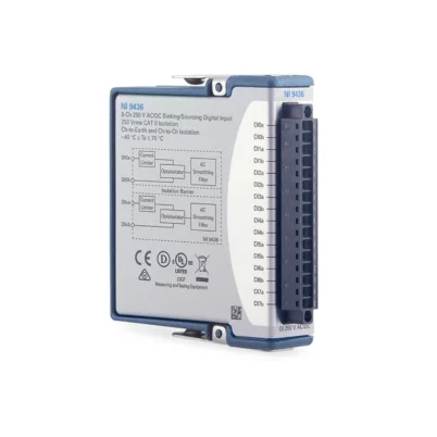
NI-9437 8-Channel High-Voltage Digital Input Module
The NI-9437 is an eight-channel C Series sinking digital input module designed for high-voltage DC monitoring. It supports nominal logic levels from 24 VDC through 240 VDC and maximum field voltages up to 250 VDC.
The module is well suited to railway, electrical power, industrial and automotive applications where conventional 24 V digital input modules do not provide sufficient voltage range. Ratiometric switching thresholds automatically adjust according to the user-supplied field voltage.
Key Features of the NI-9437
- Eight high-voltage digital input channels
- Sinking-input architecture
- 24 VDC to 250 VDC operating range
- Supports 24, 48, 72, 96, 120 and 240 VDC logic systems
- Ratiometric input thresholds
- Threshold automatically adjusts to approximately two-thirds of Vsup
- 1 µs input response
- Up to 1 MHz clock rate
- Single-ended signaling
- 250 Vrms channel-to-earth isolation
- Spring-terminal and screw-terminal versions
- Conformal-coated option
- -40°C to 70°C operating range
NI-9437 Technical Specifications
| Product Model | NI-9437 |
|---|---|
| Product Type | High-voltage C Series digital input module |
| Number of Inputs | 8 |
| Input Type | Sinking |
| Signal Type | Single-ended |
| Input Voltage Range | 24 VDC to 250 VDC |
| Nominal Logic Levels | 24, 48, 72, 96, 120 and 240 VDC |
| Threshold Type | Ratiometric to field supply |
| Approximate ON Threshold | Two-thirds of user supply voltage |
| Input Response | 1 µs |
| Maximum Clock Rate | 1 MHz |
| Channel-to-Channel Isolation | None within the input bank |
| Channel-to-Earth Isolation | 250 Vrms |
| Connector Options | Spring terminal or screw terminal |
| Operating Temperature | -40°C to 70°C |
| Bus Platform | C Series |
High-Voltage DC Monitoring
The NI-9437 allows a CompactDAQ or CompactRIO system to monitor high-voltage control and status signals without using separate voltage-divider circuitry for every channel.
It is intended for properly protected DC signal circuits. Confirm the applicable safety category, working voltage, field wiring and isolation requirements before connection.
Ratiometric Thresholds
Instead of applying one fixed voltage threshold to every supported system, the NI-9437 references its input thresholds to the connected user supply. The switching threshold automatically tracks approximately two-thirds of Vsup.
This architecture allows the module to distinguish valid states across several nominal DC control voltages. The field supply and input signal must be configured according to the official wiring diagram.
1 µs Digital Response
The 1 µs response and 1 MHz clock capability allow the NI-9437 to capture faster state changes than general-purpose high-voltage monitoring devices. Actual acquisition performance depends on the chassis and software interface.
NI-9437 Part Number and Accessories
| Part Number | Description |
|---|---|
| 783737-01 | Spring-terminal version supplied with NI-9980 terminal plug |
| 783393-01 | Standard screw-terminal version supplied with NI-9936 plug |
| 783393-02 | Conformal-coated screw-terminal version |
| NI-9980 | 10-position spring-terminal plug |
| NI-9936 | 10-position screw-terminal plug |
| High-Voltage Field Wiring | Application-rated cable selected for voltage, temperature and environment |
Confirm whether the application requires spring terminals, screw terminals or conformal coating. All connectors, wire insulation and external protection must be rated for the maximum field voltage.
NI-9437 Applications
- Railway signal monitoring
- Power-system status acquisition
- Battery-system testing
- High-voltage contact monitoring
- Industrial DC control systems
- Substation automation
- Automotive high-voltage testing
- Energy-storage validation
- Protective relay monitoring
- Hardware-in-the-loop testing
Rail and Power Applications
Railway and power systems frequently use control voltages above 24 VDC for improved noise immunity and long-distance signaling. The NI-9437 can monitor these circuits directly when all electrical and safety requirements are satisfied.
Battery and Energy Systems
The wide DC input range supports status and interlock monitoring in battery and energy-storage test systems. It should not be used as an analog battery-voltage measurement device because it reports digital state rather than precise voltage.
NI-9437 Installation Workflow
Step 1: Identify the Field Voltage
Confirm the nominal and maximum voltage of the monitored circuit and verify that it remains within the NI-9437 ratings.
Step 2: Select the Correct Variant
Choose the appropriate spring-terminal, screw-terminal or conformal-coated model.
Step 3: De-Energize the Field Circuit
Remove external power and verify the absence of hazardous voltage before installing or changing wiring.
Step 4: Connect Vsup and COM
Connect the field supply reference exactly as shown in the NI wiring documentation because it establishes the ratiometric thresholds.
Step 5: Connect the Inputs
Use correctly rated wire, insulation, ferrules, fusing and protective barriers for the field voltage.
Step 6: Verify the Logic States
Apply controlled test voltages and confirm that each input changes state at the expected threshold before connecting the production circuit.
NI-9437 Troubleshooting
Every input remains OFF
Check the Vsup and COM connections. Without the correct field-supply reference, the ratiometric input thresholds cannot operate correctly.
The input switches at an unexpected voltage
Measure the actual Vsup value and remember that the threshold tracks the user supply rather than using one fixed voltage for every application.
The input changes when nearby contactors switch
Improve cable separation, shielding, grounding and transient suppression. High-voltage industrial wiring can couple noise into long parallel signal cables.
The software misses narrow pulses
Confirm the pulse width, selected chassis and acquisition method. The module’s electrical response is only one part of the complete system timing.
The module is damaged after rewiring
Always de-energize the external high-voltage circuit before removing the terminal plug or C Series module. Verify polarity and maximum voltage before restoration.
NI-9437 Comparison
| Model | Input Configuration | Best Suited For |
|---|---|---|
| NI-9437 | 8 sinking inputs, 24 VDC to 250 VDC, 1 µs | High-voltage DC status monitoring |
| NI-9421 | 8 sinking inputs, 24 V, 100 µs | General industrial logic |
| NI-9423 | 8 high-speed 24 V inputs | Fast conventional industrial signals |
| NI-9425 | 32 sinking inputs | High-channel-count 24 V monitoring |
| NI-9350 | Functional-safety-related digital I/O | Applications requiring applicable safety functionality |
Selecting the NI-9437
Choose the NI-9437 when the test or monitoring system must read DC logic signals substantially above 30 V. Choose the NI-9421 or NI-9423 for conventional 24 V systems where high-voltage capability is unnecessary.
NI-9437 Frequently Asked Questions
What voltage range does the NI-9437 support?
It is intended for high-voltage digital signals from 24 VDC to 250 VDC.
How many inputs does it provide?
The module provides eight sinking digital input channels.
Is it an analog voltage measurement module?
No. It determines digital ON and OFF states and does not provide a precision numeric voltage measurement.
How are its logic thresholds determined?
The thresholds are ratiometric and track the connected user supply, with the operating threshold approximately two-thirds of Vsup.
Is a conformal-coated version available?
Yes. Part number 783393-02 is the conformal-coated screw-terminal version.
Can it be used in CompactDAQ and CompactRIO?
Yes, subject to the compatibility and software capabilities of the selected chassis.
Request a Quote for the NI-9437
Contact us for current availability, lead time and project pricing for the NI-9437 high-voltage digital input module. We can also help select the correct terminal version, compatible chassis and lower-voltage C Series alternatives.















