






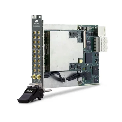
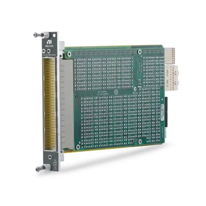
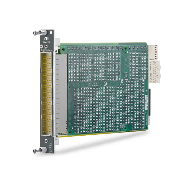
PXIe-2738 256-Crosspoint Matrix Switch Module
The PXIe-2738 is a high-density PXI Express matrix switch module designed for automated test, electronic validation and multichannel signal-routing applications. It provides a fixed 8×32 two-wire matrix with 256 crosspoints, allowing eight instrument connections to access as many as 32 devices or test-point pairs.
With 100 V, 2 A and 60 W switching capability, the PXIe-2738 can route low-level measurement signals and higher-power test signals. Electromechanical relays, a 1,000-cycle-per-second scan rate and integrated health-monitoring features make it suitable for production and long-term automated test systems.
Key Features of the PXIe-2738
- 256-crosspoint matrix switch module
- Fixed 8×32 two-wire matrix topology
- 100 V maximum switching voltage
- 2 A maximum switching and carry current per channel
- 60 W or 62.5 VA maximum switching power
- Up to 1,000 switching cycles per second
- Up to 10 MHz typical bandwidth
- Electromechanical non-latching relays
- 100 million-cycle mechanical relay life
- Onboard relay-count tracking
- Integrated temperature sensor
- Functional and resistive relay self-tests
- NI Switch Health Center compatibility
- 160-position DIN front-panel connector
- Single-slot PXI Express design
PXIe-2738 Technical Specifications
| Product Model | PXIe-2738 |
|---|---|
| Part Number | 782835-38 |
| Product Type | PXI Express Matrix Switch Module |
| Matrix Topology | 8×32 two-wire matrix |
| Number of Rows | 8 |
| Number of Columns | 32 |
| Crosspoint Count | 256 |
| Switching Mode | Two-wire |
| Maximum Switching Voltage | 100 V, channel-to-channel or channel-to-ground |
| Maximum Switching Current | 2 A per channel |
| Maximum Carry Current | 2 A per channel |
| Maximum Switching Power | 60 W or 62.5 VA |
| Minimum Switching Load | 20 mV, 1 mA |
| Initial DC Path Resistance | Less than 1.3 Ω |
| DC Isolation Resistance | 1 GΩ typical |
| Thermal EMF | Less than 10 µV |
| Bandwidth | Up to 10 MHz typical |
| Maximum Scan Rate | 1,000 cycles/s |
| Typical Relay Operate Time | 1 ms |
| Maximum Relay Operate Time | 3.3 ms |
| Simultaneous Drive Limit | 90 relays |
| Relay Type | Electromechanical, non-latching |
| Relay Contact Material | Gold-covered palladium-ruthenium |
| Mechanical Relay Life | 100 million cycles |
| Front Connector | 160-position DIN 41612 male |
| Operating Temperature | 0°C to 55°C |
| Dimensions | 3U, one-slot PXI Express module |
| Weight | 423 g |
| Bus Interface | PXI Express |
PXIe-2738 Part Number and Accessories
| Item | Part Number | Description |
|---|---|---|
| PXIe-2738 | 782835-38 | 256-crosspoint, 8×32 two-wire matrix switch module |
| 160-Pin DIN to Four D-Sub Cable | 782417-03 | Connects the module to compatible D-Sub terminal accessories |
| TBX-50 Terminal Block | 779305-01 | 50-pin screw-terminal accessory for field wiring |
| TBX-50B Terminal Block | 782866-01 | Updated 50-pin terminal block for signal connections |
| 160-Pin DIN to 160-Pin DIN Cable | 781090-02 | Custom DIN-to-DIN connectivity cable |
| 160-Pin DIN to Bare-Wire Cable | 781090-03 | Bare-wire cable for custom fixtures and interfaces |
The required cables and terminal blocks depend on the test-fixture design and preferred wiring method. Verify connector pinouts, cable length and terminal compatibility before ordering.
8×32 Two-Wire Matrix Architecture
The PXIe-2738 contains eight two-wire rows and 32 two-wire columns. Any row can be connected to any column through an independently controlled crosspoint, providing a total of 256 possible routing locations.
This topology is useful when as many as eight instruments must access 32 devices, channels or test-point pairs. Software can dynamically change the connections as the automated test sequence progresses.
Flexible Instrument-to-DUT Routing
The matrix architecture allows measurement and stimulus instruments to be assigned to different device connections without manually changing cables. Rows can be connected to digital multimeters, source measurement units, digitizers or power supplies, while columns connect to the device under test.
Multiple crosspoints can be closed simultaneously when the resulting routes are electrically compatible and remain within the module’s relay-drive, voltage, current and power limits.
Two-Wire Signal Switching
Every matrix connection switches both the positive and negative signal conductors together. This provides better isolation than switching only one conductor and is suitable for differential, floating and paired signal connections.
For precision low-resistance measurements, consider whether a four-wire matrix is required. A two-wire path includes relay, cable and fixture resistance in the measurement result.
100 V and 2 A Switching Capability
The PXIe-2738 can switch voltages up to 100 V and currents up to 2 A per channel. Maximum switching power must not exceed 60 W for DC loads or 62.5 VA for AC loads.
Voltage, current and power ratings must be considered simultaneously. Inductive loads such as motors, solenoids and relays may require external transient suppression to protect the switch contacts.
Measurement Category I Operation
The module is intended for Measurement Category I or CAT O signal circuits that are not directly connected to building mains. It must not be used for connections to CAT II, CAT III or CAT IV circuits.
The maximum supported signal level is 70 Vrms, 100 V peak or 100 VDC. Appropriate insulation and safety procedures are required when hazardous voltages are present.
Low Thermal EMF Performance
Thermal EMF below 10 µV helps reduce voltage offsets introduced by relay contacts and internal traces. This makes the PXIe-2738 suitable for routing low-level voltage signals to precision measurement instruments.
System-level accuracy also depends on cable construction, terminal connections, grounding, temperature gradients, source impedance and measurement settling time.
DC Path Resistance
The combined two-wire path from one row to one column has initial resistance below 1.3 Ω. This resistance includes the high and low relay contacts and internal circuit-board traces.
Relay resistance generally remains stable through most of the relay’s service life and increases rapidly near end of life. Applications sensitive to resistance should periodically verify the complete signal path.
10 MHz Typical Bandwidth
The PXIe-2738 supports signal routing with typical bandwidth up to 10 MHz. It is suitable for DC, sensor, control and moderate-frequency electronic signals.
Actual system bandwidth and signal integrity depend on the selected cable, fixture layout, termination, source impedance, load impedance and number of closed crosspoints.
Fast Automated Scanning
With a scan rate of up to 1,000 cycles per second and a typical relay operating time of 1 ms, the PXIe-2738 supports high-throughput automated routing sequences.
The final test rate also depends on measurement aperture, instrument settling time, software configuration and the time required for the device under test to stabilize after each route change.
Electromechanical Relay Performance
The PXIe-2738 uses non-latching electromechanical relays with gold-covered palladium-ruthenium contacts. These relays provide physical signal isolation and support switching of both low-level and higher-power signals.
The expected mechanical relay life is 100 million cycles. Electrical relay life depends on the voltage, current, load type and frequency at which each crosspoint is operated.
NI Switch Health Center
The PXIe-2738 provides system-health features through the NI Switch Health Center. These capabilities help maintenance teams monitor deployed switching systems and identify potential relay problems before they interrupt production testing.
Available health information includes onboard relay counts, module temperature data, functional relay tests and resistive relay tests.
Onboard Relay-Count Tracking
Relay-count tracking records how often individual crosspoints operate. Engineers can identify heavily used signal routes and distribute switch activity across other crosspoints when the test architecture permits.
Relay-count information can also support preventive-maintenance schedules. The PXIe-2738 relays are field replaceable if an individual relay reaches the end of its useful life.
Temperature Monitoring
The integrated temperature sensor provides additional information about module operating conditions. This is useful in densely populated PXI Express chassis and test systems operating continuously for long periods.
When the ambient temperature exceeds 50°C, the number of channels carrying higher current may need to be reduced according to the module’s load-derating requirements.
Typical PXIe-2738 Applications
- Automated electronic device testing
- Production and manufacturing test systems
- Printed circuit board functional testing
- Multiple-instrument signal routing
- Semiconductor validation
- Battery and power-system testing
- Sensor and transducer test systems
- Data acquisition signal routing
- Design verification and characterization
- Reliability and environmental testing
Multichannel Measurement Systems
The PXIe-2738 can connect multiple device-under-test channels to shared measurement instruments. For example, it can be paired with a PXIe-4080 digital multimeter to perform automated voltage, current and resistance measurements across different test points.
This approach can reduce instrument count and simplify fixture wiring when simultaneous measurements are not required on every channel.
NI-SWITCH Software Support
The PXIe-2738 is controlled through the NI-SWITCH instrument driver. NI-SWITCH provides functions for connecting and disconnecting matrix crosspoints, creating scan lists, reading relay counts and managing switching sequences.
The driver supports integration with LabVIEW, LabWindows/CVI and supported text-based programming environments.
NI Switch Executive Integration
NI Switch Executive allows engineers to create named routes and route groups using meaningful signal names. It can simplify applications containing the PXIe-2738, multiple switch modules and complex test fixtures.
Named routes make test software easier to understand and maintain because application code does not need to control every physical crosspoint directly.
PXI Express Chassis Integration
The PXIe-2738 occupies one slot in a compatible PXI Express chassis. It can operate alongside digital multimeters, source measurement units, oscilloscopes, digitizers and programmable power supplies.
Before installation, confirm chassis slot compatibility, available cooling capacity, connector clearance and support for the required NI-SWITCH software version.
PXIe-2738 Troubleshooting
The PXIe-2738 is not detected in NI MAX
Confirm that the module is fully seated in a compatible PXI Express slot. Check chassis power, controller communication and NI-SWITCH installation, then restart NI Measurement & Automation Explorer.
A row cannot connect to a column
Verify the row and column names used by the application. Check the external cable, terminal block and fixture wiring, then confirm that another route has not created an electrical conflict.
Measurements show excessive resistance
Remember that the two-wire path includes relay, cable, connector and fixture resistance. Inspect all connections, review the relay resistive self-test and consider a four-wire switching solution for precision low-resistance measurements.
Measurements are unstable after switching
Allow sufficient relay and signal settling time before taking the measurement. Check cable shielding, grounding, source impedance, temperature gradients and the measurement instrument’s input settings.
The scan rate is lower than expected
Review the instrument aperture, software loop, relay settling time and device-under-test stabilization requirements. The complete measurement system determines actual throughput.
The module temperature is high
Check chassis airflow, fan operation and adjacent module power consumption. Review the load-derating requirements when operating above 50°C, especially when several channels carry high current.
A relay fails the health test
Disconnect external signals and repeat the functional or resistive self-test. Inspect the fixture and cable before concluding that the relay has failed. A failed relay may require field replacement or module service.
PXIe-2738 Comparison
| Model | Matrix Configuration | Best Suited For |
|---|---|---|
| PXIe-2737 | 4×64 two-wire matrix | Fewer instruments connected to more DUT channels |
| PXIe-2738 | 8×32 two-wire matrix | Balanced instrument and DUT connection capacity |
| PXIe-2739 | 16×16 two-wire matrix | Systems requiring more instrument-side row connections |
| PXIe-2529 | 4×32, 8×16 or dual 4×16 two-wire | Lower crosspoint count with configurable topology |
| PXIe-2532B | Configurable high-density matrix | Systems requiring additional topology and expansion options |
Recommended Related Products
- PXIe-2737 4×64 Matrix Switch Module
- PXIe-2739 16×16 Matrix Switch Module
- PXIe-2529 128-Crosspoint Matrix Switch Module
- PXIe-2532B High-Density Matrix Switch Module
- PXIe-4080 Digital Multimeter
- View More NI PXI and PXI Express Modules
Selecting the Right Matrix Topology
Choose the PXIe-2738 when the system requires eight instrument-side connections and as many as 32 device or test-point connections. Its 8×32 topology provides a balanced arrangement for automated systems using several measurement and stimulus instruments.
Select the PXIe-2737 when fewer instruments need access to more DUT channels. Select the PXIe-2739 when the application requires more row connections and an equal 16×16 layout.
PXIe-2738 vs PXIe-2529
The PXIe-2738 provides a fixed 8×32 matrix with 256 crosspoints, while the PXIe-2529 provides 128 crosspoints and supports 4×32, 8×16 or dual 4×16 configurations through different terminal blocks.
The PXIe-2738 is better suited to applications requiring more total crosspoints, 2 A switching and advanced relay-health monitoring. The PXIe-2529 may be preferred when configurable topology or 150 V signal capability is more important.
Why Choose the PXIe-2738?
- Provides 256 two-wire crosspoints in one PXI Express slot
- Connects as many as eight instruments to 32 DUT channels
- Supports 100 V, 2 A and 60 W signal routing
- Offers scanning rates up to 1,000 cycles per second
- Includes relay-count and temperature monitoring
- Supports functional and resistive relay self-tests
- Integrates with NI-SWITCH and NI Switch Executive
Frequently Asked Questions
What is the PXIe-2738?
The PXIe-2738 is a 256-crosspoint PXI Express matrix switch module that provides a fixed 8×32 two-wire topology for automated signal-routing applications.
How many crosspoints does the PXIe-2738 provide?
It provides 256 crosspoints, calculated from eight rows multiplied by 32 columns.
What is the maximum switching voltage?
The maximum switching voltage is 100 V between channels or between a channel and ground for CAT I or CAT O signal applications.
What is the maximum switching current?
The PXIe-2738 can switch and carry up to 2 A per channel, subject to its switching-power and temperature-derating limits.
What is the maximum scan rate?
The module supports switching rates of up to 1,000 cycles per second. Actual test throughput also depends on measurement and signal-settling requirements.
Does the PXIe-2738 support four-wire measurements?
The native topology is two-wire. Precision four-wire measurements require an appropriate four-wire switching architecture or coordinated use of multiple signal paths.
What health-monitoring features are available?
The PXIe-2738 provides onboard relay counting, temperature monitoring, functional relay testing and resistive relay testing through the NI Switch Health Center.
Can the PXIe-2738 relays be replaced?
Yes. The electromechanical relays are field replaceable, helping extend the operational life of production and laboratory test systems.
What is the part number for the PXIe-2738?
The standard NI part number for the PXIe-2738 is 782835-38.
Request a Quote for the PXIe-2738
Contact us for current availability, lead time and project pricing for the PXIe-2738 256-Crosspoint Matrix Switch Module. We can also help identify compatible cables, TBX terminal blocks, PXI Express chassis and measurement instruments for your automated test system.















