




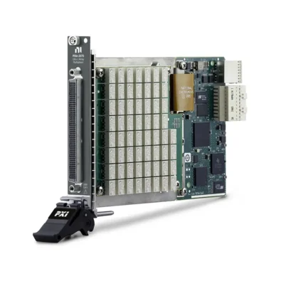
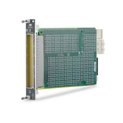
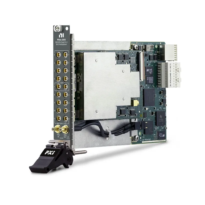
PXIe-2593 500 MHz RF Multiplexer Switch
The NI PXIe-2593 is a 16-channel, 500 MHz, 50 Ω PXI Express RF multiplexer switch module for automated signal routing. It can be programmatically configured as an unterminated multiplexer, externally terminated multiplexer or dimensionally flexible sparse matrix.
The PXIe-2593 supports several standard topologies, including 16×1, 8×1 terminated, dual 4×1 terminated, dual 8×1 and independent operation. This flexibility makes it suitable for RF, video, pulse, communications and general-purpose ATE systems.
Key Features of the PXIe-2593
- 16 available RF channels
- DC to 500 MHz specified RF range
- 50 Ω nominal characteristic impedance
- 16×1 multiplexer topology
- 8×1 externally terminated topology
- Dual 4×1 externally terminated topology
- Dual 8×1 multiplexer topology
- Independent relay configuration
- 150 V maximum switching voltage
- 0.5 A switching current per channel
- 1 A carry current per channel
- 10 W maximum switching and RF carry power
- Front-panel and PXI trigger support
- NI-SWITCH and NI Switch Executive compatibility
PXIe-2593 Technical Specifications
| Product Model | PXIe-2593 |
|---|---|
| Part Number | 780587-93 |
| Product Type | PXI Express RF Multiplexer Switch |
| Number of Channels | 16 |
| Specified RF Range | DC to 500 MHz |
| Characteristic Impedance | 50 Ω nominal |
| Maximum Switching Voltage | 150 V, CAT I |
| Maximum Switching Current | 0.5 A per channel |
| Maximum Carry Current | 1 A per channel |
| Maximum Switching Power | 10 W per channel |
| Maximum RF Carry Power | 10 W up to 500 MHz |
| Initial DC Path Resistance | Less than 1 Ω |
| 8×1 Insertion Loss | Less than 0.9 dB to 200 MHz; less than 1.6 dB to 500 MHz |
| 16×1 Insertion Loss | Less than 1.2 dB to 200 MHz; less than 1.9 dB to 500 MHz |
| Typical 8×1 3 dB Bandwidth | Greater than 900 MHz |
| Typical 16×1 3 dB Bandwidth | Greater than 750 MHz |
| Typical Relay Operate Time | 2.4 ms |
| Maximum Relay Operate Time | 4.4 ms |
| Listed Scan Rate | 100 cycles/s |
| Bus Interface | PXI Express |
PXIe-2593 Cables and Accessories
| Accessory | Part Number | Description |
|---|---|---|
| MCX-MCX Coaxial Cable | 188374-0R15 | 50 Ω MCX male-to-male cable, 15 cm |
| MCX-BNC Coaxial Cable | 188375-01 | 50 Ω MCX male-to-BNC male cable, 1 m |
| MCX-SMA Coaxial Cable | 188377-0R3 | 50 Ω MCX male-to-SMA male cable, 30 cm |
| 50 Ω MCX Terminator | 778831-01 | External termination for applicable terminated topologies |
16×1 Multiplexer Topology
The 16×1 topology connects any one of sixteen input channels to a single common path. It is useful when one instrument must measure several DUT outputs or when several sources share one destination.
The 16×1 path has slightly higher insertion loss and lower typical bandwidth than the shorter 8×1 topology.
8×1 Terminated Multiplexer
The PXIe-2593 does not contain built-in terminations. Its terminated topologies use external 50 Ω MCX terminators connected to the appropriate channel ports.
External termination helps provide a defined load to inactive signal paths and may reduce reflections in RF systems. Confirm terminator power handling before applying an active signal.
Dual 8×1 and Dual 4×1 Operation
Dual-bank configurations allow two instruments or two DUT groups to be routed independently. The dual 4×1 terminated topology is useful for smaller RF routing groups that require external 50 Ω termination.
Independent Relay Operation
Independent operation exposes individual relay functions for custom sparse-matrix routing. Engineers can combine channels and commons to create application-specific routing structures.
All routes should be checked for conflicts before relay actuation, particularly when multiple active sources are connected.
High-Voltage Signal Routing
Although designed as a 50 Ω RF multiplexer, the PXIe-2593 supports switching voltages up to 150 V for Measurement Category I circuits. Maximum current and power limits must be observed at the same time.
The module must not be connected to mains distribution circuits or Measurement Category II, III or IV signals.
Hardware Triggering
Input and output triggers can be routed through PXI trigger lines 0 through 7 and the front-panel trigger connectors. The minimum supported input pulse width is 150 ns.
Hardware triggering allows route changes to be coordinated with digitizers, generators and automated test sequences.
Typical PXIe-2593 Applications
- RF source and receiver selection
- Video signal routing
- Oscilloscope and digitizer multiplexing
- Pulse and timing signal distribution
- Communications equipment testing
- Multi-DUT production test
- Automated instrument sharing
- Dimensionally flexible sparse matrices
NI-SWITCH Software Support
The PXIe-2593 is controlled with the NI-SWITCH driver. Software can select a topology, connect channels to commons, create scan lists, configure triggering and monitor switching operations.
NI Switch Executive allows engineers to define named routes and route groups, simplifying systems containing multiple PXIe-2593 modules.
PXIe-2593 Troubleshooting
The module is not detected
Confirm that the PXIe-2593 is fully seated in a compatible PXI Express slot. Check chassis communication and reinstall or repair the NI-SWITCH driver if necessary.
The selected channel has no signal
Verify the active topology, route name, common selection and external cable. A route created for one topology may not be valid after the topology changes.
The terminated topology does not provide 50 Ω
Confirm that the required external MCX terminators are installed on the correct channel ports. The module does not contain built-in terminations.
Insertion loss is higher than expected
Inspect cables, adapters, terminators and connectors. Confirm that the measurement is being compared with the correct 8×1 or 16×1 insertion-loss limit.
The RF source becomes unstable during switching
A channel can be momentarily unterminated while a relay actuates. Reduce or disable RF power before switching if the source cannot safely tolerate reflected power.
PXIe-2593 Comparison
| Model | Topology | Maximum Frequency | Best Suited For |
|---|---|---|---|
| PXIe-2593 | Up to 16×1, configurable | 500 MHz specified | Flexible high-channel-count RF routing |
| PXI-2593 | Up to 16×1, configurable | 500 MHz specified | Existing PXI-based switching systems |
| PXI-2594 | 4×1 | 2.5 GHz | Higher-frequency four-channel routing |
| PXI-2545 | Terminated 4×1 | 2.7 GHz | Internally terminated RF paths |
Recommended Related Products
- PXI-2593 500 MHz RF Multiplexer
- PXI-2594 2.5 GHz RF Multiplexer
- PXI-2545 2.7 GHz Terminated RF Multiplexer
- PXI-2595 5 GHz RF Multiplexer
- View More NI PXI Switch Modules
Frequently Asked Questions
What is the PXIe-2593 part number?
The standard NI part number is 780587-93.
How many channels does it provide?
The module provides 16 signal channels that can be arranged into several supported topologies.
Does it contain internal 50 Ω terminations?
No. Applicable terminated topologies require external 50 Ω MCX terminators.
What is the maximum switching voltage?
The maximum is 150 V for Measurement Category I signal circuits.
What is the maximum switching current?
The maximum switching current is 0.5 A per channel, with up to 1 A carry current.
Which connector type is used?
The module uses MCX RF connections and separate front-panel trigger connections.
Which software controls the module?
Use NI-SWITCH for direct control and NI Switch Executive for named-route management.
Request a Quote for the PXIe-2593
Contact us for availability and project pricing for the PXIe-2593 500 MHz RF Multiplexer. We can also help identify MCX cables, terminators and alternative RF switch modules.















