






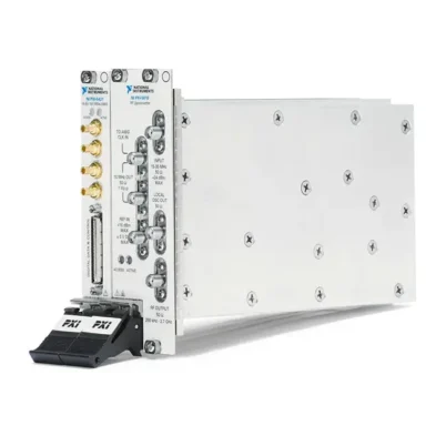
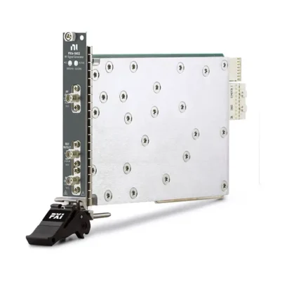
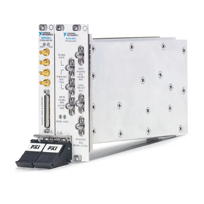
PXI-5671 2.7 GHz PXI Vector Signal Generator
The PXI-5671 is a modular PXI vector signal generator designed for communications, semiconductor, aerospace, defense, consumer-electronics and wireless-device testing. It generates continuous-wave and vector-modulated RF signals over a frequency range from 250 kHz to 2.7 GHz.
The PXI-5671 combines an NI PXI-5441 arbitrary waveform generator with an NI PXI-5610 RF upconverter. The PXI-5441 generates and digitally processes the intermediate-frequency waveform, while the PXI-5610 translates that waveform to the selected RF carrier frequency.
Integrated quadrature digital upconversion reduces waveform download and generation requirements by performing interpolation, filtering, I/Q mixing and frequency translation on the PXI-5441. The system supports analog and digital modulation formats including AM, FM, PM, ASK, FSK, MSK, GMSK, PSK, QPSK, PAM and QAM.
Key Features of the PXI-5671
- 250 kHz to 2.7 GHz RF frequency range
- 20 MHz instantaneous modulation bandwidth
- Up to +10 dBm RF output power
- 16-bit arbitrary waveform generation
- 100 MS/s analog update rate
- Quadrature digital upconversion
- FIR and CIC interpolation filters
- Numerically controlled oscillator
- Digital gain, offset and prefilter processing
- AM, FM and PM analog modulation
- ASK, FSK, MSK, GMSK, PSK and QPSK generation
- PAM and QAM signal generation
- Support for custom modulation formats
- Approximately ±0.7 dB amplitude accuracy
- Typical -95 dBc/Hz phase noise at 10 kHz offset
- Typical -120 dBm/Hz output noise density at 0 dBm
- 32 MB, 256 MB and 512 MB memory options
- Waveform scripting and sequencing
- Direct waveform download support
- PXI triggering and clock synchronization
- NI-RFSG and NI-FGEN software support
PXI-5671 Technical Specifications
| Product Model | PXI-5671 |
|---|---|
| Product Type | PXI vector signal generator |
| Frequency Range | 250 kHz to 2.7 GHz |
| Instantaneous Modulation Bandwidth | 20 MHz |
| Maximum RF Output Power | +10 dBm |
| Amplitude Accuracy | Approximately ±0.7 dB |
| Typical Output Noise Density at 0 dBm | -120 dBm/Hz |
| Typical Phase Noise | -95 dBc/Hz at a 10 kHz offset |
| Typical CW Tuning Time | 35 ms |
| Vector Modulation Bandwidth Flatness | ±0.5 dB typical with equalization enabled |
| Group Delay Deviation | ±20 ns typical within the vector modulation bandwidth |
| Analog Modulation Formats | AM, FM and PM |
| Digital Modulation Formats | ASK, FSK, MSK, GMSK, PSK, QPSK, PAM, QAM and custom formats |
| AWG Resolution | 16 bits |
| Maximum Analog Update Rate | 100 MS/s |
| AWG Analog Bandwidth | 43 MHz |
| Digital Upconversion | Supported |
| Onboard Signal Processing | FIR, CIC interpolation, gain, offset, NCO and I/Q mixing |
| Onboard Memory Options | 32 MB, 256 MB or 512 MB |
| RF Upconverter Module | PXI-5610 |
| Arbitrary Waveform Generator | PXI-5441 |
| RF Output Connector | SMA |
| Reference and Intermodule Connections | SMA and SMB coaxial connectors |
| Trigger Source Module | PXI-5441 |
| Total Slot Requirement | Three PXI slots |
| PXI-5610 Format | 3U, two-slot PXI module |
| PXI-5441 Format | 3U, one-slot PXI hybrid-compatible module |
| Combined Weight | 1,510 g nominal |
| Bus Interface | Conventional PXI |
| Software Support | NI-RFSG, NI-FGEN, LabVIEW and compatible text-based environments |
| Lifecycle Status | No longer available from NI |
PXI-5671 Part Numbers and Memory Options
| Part Number | Onboard Waveform Memory | Description |
|---|---|---|
| 779079-02 | 32 MB | PXI-5671 vector signal generator with PXI-5441 and PXI-5610 modules |
| 779079-03 | 256 MB | PXI-5671 with expanded memory for longer waveform records |
| 779079-04 | 512 MB | PXI-5671 with the largest available onboard memory configuration |
The three PXI-5671 part numbers provide the same RF frequency range, modulation bandwidth, channel count and upconverter architecture. The primary difference is the amount of waveform memory installed on the PXI-5441.
PXI-5671 System Components
| Component | Component Part Number | Function |
|---|---|---|
| PXI-5610 | 778737-01 | 250 kHz to 2.7 GHz RF upconverter |
| PXI-5441 | Memory dependent | 16-bit arbitrary waveform generator with onboard signal processing |
| Replacement Cable Kit | 190846-01 | Semi-flexible coaxial cables for the IF and reference-clock connections |
| Cable Wrenches | 746016-01 | Tools for handling and securing the semi-flexible cable connectors |
| SMA Torque Wrench | 780487-01 | Optional 1 N·m wrench for compatible SMA connections |
The PXI-5671 model name refers to a configured multi-module instrument rather than a single physical module. A complete system requires the PXI-5610, PXI-5441 and the correct intermodule cables.
PXI-5441 Arbitrary Waveform Generator
The PXI-5441 generates the intermediate-frequency waveform used by the PXI-5671. It provides 16-bit output resolution, a 100 MS/s update rate and 43 MHz analog bandwidth.
Unlike the PXI-5421 used in the PXI-5670, the PXI-5441 includes onboard signal processing. This allows interpolation, digital gain, filtering and frequency translation to occur on the module rather than requiring every final output sample to be stored in memory.
The PXI-5441 can also be used independently as a general-purpose arbitrary waveform generator when the complete RF upconversion system is no longer required.
PXI-5610 RF Upconverter
The PXI-5610 receives an intermediate-frequency waveform from the PXI-5441 and converts it to an RF carrier between 250 kHz and 2.7 GHz. It contains the local oscillator, mixers, filters, attenuators and level-control circuitry.
NI-RFSG automatically selects the appropriate intermediate frequency, conversion path and attenuation according to the requested RF carrier frequency and output power.
Quadrature Digital Upconversion
Quadrature digital upconversion is a primary difference between the PXI-5671 and the earlier PXI-5670. Complex baseband I/Q data can be interpolated, filtered and digitally shifted to the required intermediate frequency on the PXI-5441.
This architecture reduces the number of waveform samples that must be created by the host and downloaded to the instrument. It also allows carrier-related adjustments without rebuilding the complete final-rate waveform.
FIR and CIC Interpolation Filters
The PXI-5441 provides finite impulse response and cascaded integrator-comb interpolation filters. Interpolation increases the effective output rate while controlling spectral images created during digital upconversion.
The selected interpolation factor must be compatible with the waveform I/Q rate and occupied bandwidth. Incorrect settings can introduce unwanted spectral images or restrict the modulation bandwidth.
Numerically Controlled Oscillator
An onboard numerically controlled oscillator performs digital frequency shifting before the waveform reaches the DAC. The NCO can translate baseband I/Q data to an appropriate intermediate frequency for the PXI-5610.
Frequency shifting in hardware can reduce waveform download time and simplify frequency-agile test sequences.
Digital Gain and Offset Processing
Onboard gain and offset processing allows waveform levels to be adjusted without regenerating the source data. Digital scaling can support automated power changes and waveform calibration.
Excessive digital gain can cause clipping, while large attenuation reduces the number of DAC codes used. Review waveform headroom and signal-to-noise requirements when configuring digital gain.
250 kHz to 2.7 GHz Frequency Coverage
The PXI-5671 covers RF frequencies from 250 kHz through 2.7 GHz. This range supports many cellular, RFID, navigation, wireless-sensor, broadcast and general communications bands.
Systems requiring operation above 2.7 GHz should use a higher-frequency vector signal generator or vector signal transceiver. Verify both carrier-frequency coverage and instantaneous bandwidth before selecting a replacement.
20 MHz Instantaneous Bandwidth
The generator provides 20 MHz of instantaneous modulation bandwidth. It can reproduce complex RF signals whose occupied bandwidth remains within this limit without changing the RF center frequency.
Actual modulation performance depends on the I/Q sample rate, filter configuration, equalization and waveform scaling. Use a compatible vector signal analyzer to confirm error vector magnitude and spectral behavior.
RF Output Power
The PXI-5671 can generate RF output power up to +10 dBm. Internal attenuators and digital waveform scaling provide control across a broad range of lower output levels.
Cable loss, switches, attenuators and fixture insertion loss reduce the level reaching the DUT. For accurate receiver or component testing, establish a calibrated reference plane at the DUT input.
Amplitude Accuracy
The amplitude accuracy is approximately ±0.7 dB under the applicable calibration and environmental conditions. Internal temperature correction improves stability as the module operates.
Allow adequate warm-up time and maintain the calibration intervals for both component modules. The PXI-5610 and PXI-5441 have separate calibration records and service requirements.
Phase Noise and Output Noise
Typical phase noise is approximately -95 dBc/Hz at a 10 kHz offset. At a 0 dBm output setting, typical output noise density is approximately -120 dBm/Hz.
Phase noise and residual output noise affect receiver-sensitivity, adjacent-channel and modulation-quality tests. Performance varies with RF frequency, output power and offset frequency.
Analog Modulation
The PXI-5671 supports amplitude, frequency and phase modulation. Software can configure the carrier, deviation, modulation rate and output power for automated analog-radio testing.
Analog modulation can be combined with frequency and power sweeps to characterize receiver response across different operating conditions.
Digital Modulation
The generator supports ASK, FSK, MSK, GMSK, PSK, QPSK, PAM and QAM. Custom I/Q waveforms can implement proprietary formats and research signals that fit within the 20 MHz bandwidth.
Waveforms can be created with compatible NI toolkits or external software and downloaded through NI-RFSG.
QAM and QPSK Generation
QAM and QPSK signals can be generated for receiver, transmitter and component testing. Pulse-shaping filters can control occupied bandwidth and symbol transitions.
For representative QPSK, 16-QAM and 64-QAM configurations, the PXI-5671 can achieve low error vector magnitude when equalization is enabled and the waveform is configured within supported limits.
GMSK and Wireless Signal Generation
Gaussian minimum-shift keying support is useful for wireless standards that require constant-envelope modulation. The programmable waveform architecture also supports customized Gaussian filtering and symbol sequences.
Software add-ons were available for standards such as WCDMA, DVB-H and ZigBee. Compatibility among the toolkit, LabVIEW version and NI-RFSG installation should be checked before rebuilding a legacy system.
Direct Waveform Download
The PXI-5671 supports direct waveform download for compatible configurations. Waveform data can be written to the instrument immediately instead of first being copied to host memory for later transfer.
Direct download can improve performance for large waveform records. It requires supported settings, including an I/Q rate no greater than 8.33 MS/s and compatible power-level, equalization and I/Q-swap configurations.
Waveform Scripting and Sequencing
The PXI-5441 supports waveform scripts that can repeat, branch and sequence stored waveform segments. Test software can generate packet bursts, different modulation states and defined idle intervals without repeatedly downloading the entire sequence.
Memory capacity determines how many and how long the stored waveform records can be. The 512 MB version is the best PXI-5671 option for long nonrepeating signals.
Attenuator Hold
Attenuator-hold mode prevents the PXI-5610 from switching its internal attenuator during a defined power sweep. Lower signal levels are produced by digitally scaling the waveform.
This can make power changes more monotonic and repeatable. The tradeoff is reduced digital dynamic range and potentially higher relative noise at lower output levels.
Intermodule Cable Connections
The PXI-5441 waveform output connects to the PXI-5610 input through a semi-flexible coaxial cable. A second cable routes the PXI-5610 reference output to the PXI-5441 clock input.
Both connections are required for normal RFSG operation. Incorrect cable routing, loose connectors or damaged semi-flexible cables can cause reference-lock errors, missing output or poor modulation performance.
Reference Clock Synchronization
The PXI-5610 contains a stable 10 MHz reference and supplies it to the PXI-5441. The upconverter can also lock to an external 10 MHz reference or PXI_CLK10 backplane clock.
Sharing a frequency reference with other RF instruments improves frequency coherence in multi-instrument systems.
PXI Hardware Triggering
The PXI-5441 handles PXI backplane triggering for the complete PXI-5671. Triggered generation can be synchronized with vector signal analyzers, digitizers, switches and DUT control equipment.
When configuring terminal routes in software, use the PXI-5441 resource associated with the combined generator. Selecting the PXI-5610 as the trigger endpoint will not provide the required backplane trigger route.
Receiver Testing
The PXI-5671 can generate controlled RF signals for receiver sensitivity, demodulation, selectivity and packet-error-rate testing. Carrier frequency, power, waveform and modulation parameters can be changed automatically.
External attenuation or filtering may be required for very-low-level receiver measurements where generator noise or leakage could affect the result.
RFID and Wireless Sensor Testing
Custom waveform sequencing supports the burst and command structures used by RFID and wireless sensor systems. Engineers can vary packet content, frequency and power to evaluate receiver behavior.
Automated tests can characterize communication range, packet-error rate, adjacent-channel rejection and response to impaired signals.
GPS and Navigation Signal Simulation
The 512 MB PXI-5671 was supported by legacy NI GPS simulation software for generating GPS-related RF waveforms. Deep memory allowed longer navigation-signal records to be played without frequent host interaction.
Before rebuilding a GPS simulation system, verify the required toolkit license, LabVIEW version, waveform files and operating-system compatibility.
Semiconductor RF Testing
The PXI-5671 can generate CW and modulated signals for amplifiers, mixers, filters, receiver ICs and other RF semiconductor devices. PXI switches can route the output to multiple DUT sites or measurement paths.
The generator can be paired with a vector signal analyzer, digitizer or power meter to create a complete automated RF characterization system.
Software-Defined Radio Research
Researchers can create baseband I/Q data in software and use the PXI-5671 to interpolate, frequency-shift and upconvert the waveform to RF. This supports experimentation with new modulation, coding and synchronization methods.
The combination of user-defined waveforms and modular PXI instrumentation provides more flexibility than a fixed-function signal generator.
NI-RFSG Software Support
NI-RFSG controls the PXI-5441 and PXI-5610 as one logical vector signal generator. It coordinates frequency, output power, waveform download, digital upconversion, attenuation and triggering.
Applications should normally initialize and control the complete PXI-5671 through NI-RFSG instead of configuring its two component modules independently.
NI-FGEN Software Support
The PXI-5441 can be controlled independently with NI-FGEN when used as a standalone arbitrary waveform generator. NI-FGEN provides access to waveform generation, scripting, signal processing and triggering functions.
Do not open competing NI-RFSG and NI-FGEN sessions to the same hardware simultaneously. Close one driver session before changing the module’s operating role.
Typical PXI-5671 Applications
- RF receiver sensitivity testing
- QAM and QPSK communications testing
- GMSK and wireless-device testing
- WCDMA signal generation
- ZigBee device validation
- RFID system development
- GPS signal simulation
- Software-defined radio research
- Semiconductor RF component testing
- Aerospace and defense communications testing
- Automated production testing
- Custom vector-modulated signal generation
PXI-5671 Troubleshooting
The PXI-5671 Is Not Detected
Confirm that both the PXI-5610 and PXI-5441 are installed in compatible PXI or PXI hybrid slots. Check chassis power, controller communication and NI-RFSG installation, then inspect both modules in NI Measurement & Automation Explorer.
NI MAX Shows Two Modules but No Combined Generator
Verify that the modules are correctly associated as a PXI-5671. Check NI-RFSG compatibility and confirm that the intermodule cables are installed in the specified ports.
There Is No RF Output
Confirm that generation has been initiated and that the RF output is enabled. Verify the carrier frequency, power setting, trigger state and cable connection to the PXI-5610 RF OUTPUT port.
The Reference Clock Does Not Lock
Inspect the cable between the PXI-5610 10 MHz output and PXI-5441 clock input. Reseat the connectors carefully and replace the cable if it has been sharply bent or mechanically damaged.
The Modulated Signal Has High EVM
Check waveform scaling, interpolation, filtering, equalization and I/Q configuration. Allow sufficient warm-up time and confirm that both hardware modules are within their calibration intervals.
The Waveform Is Clipping
Reduce the digital gain or normalize the I/Q samples to provide sufficient headroom. Clipping produces spectral regrowth and degrades modulation quality.
Direct Download Cannot Be Enabled
Confirm that the I/Q rate and power-level configuration satisfy the direct-download requirements. Digital equalization and I/Q swapping may need to be disabled.
Output Power Changes Are Discontinuous
Mechanical attenuator switching can produce small transitions. Use attenuator hold when smooth power changes are more important than maximum digital dynamic range.
A PXI Trigger Route Does Not Work
Route the trigger through the PXI-5441 associated with the generator. The PXI-5441 is the trigger-source module for the PXI-5671.
The System Requires Three Slots
The PXI-5610 occupies two slots and the PXI-5441 occupies one. Three adjacent compatible slots and adequate chassis cooling are required.
PXI-5671 Comparison with Similar PXI Vector Signal Generators
| Model | Primary Configuration | Best Suited For |
|---|---|---|
| PXI-5670 | 250 kHz to 2.7 GHz, 20 MHz bandwidth, PXI-5421 AWG | Legacy vector signal generation without onboard DUC |
| PXI-5671 | 250 kHz to 2.7 GHz, 20 MHz bandwidth, PXI-5441 with DUC | Legacy RF generation with onboard signal processing |
| PXIe-5672 | 250 kHz to 2.7 GHz, 20 MHz bandwidth, PXI Express AWG | Faster waveform transfer in PXI Express systems |
| PXIe-5673E | 50 MHz to 6.6 GHz, 100 MHz bandwidth | Higher-frequency and wider-bandwidth RF generation |
| PXIe-5840 | Vector signal transceiver with user-programmable FPGA | Modern software-designed RF generation and analysis |
PXI-5671 vs PXI-5670
Both models use the PXI-5610 upconverter and cover 250 kHz to 2.7 GHz with 20 MHz modulation bandwidth. The PXI-5670 uses the PXI-5421 AWG, while the PXI-5671 uses the higher-performance PXI-5441.
The PXI-5671 adds quadrature digital upconversion, interpolation filters and onboard signal processing. This reduces waveform data requirements and provides greater flexibility for modulated-signal generation.
PXI-5671 vs PXIe-5672
The PXIe-5672 uses the PXI-5610 with a PXI Express arbitrary waveform generator. It maintains the same 2.7 GHz upper frequency and 20 MHz modulation bandwidth.
Choose the PXI-5671 for existing conventional PXI systems. Choose the PXIe-5672 when faster waveform downloads and PXI Express communication are required.
PXI-5671 vs PXIe-5673E
The PXIe-5673E extends frequency coverage to 6.6 GHz and provides 100 MHz of instantaneous bandwidth. It is better suited to wider-bandwidth wireless standards and higher-frequency devices.
The PXI-5671 remains appropriate for legacy applications below 2.7 GHz whose occupied bandwidth does not exceed 20 MHz.
PXI-5671 vs PXIe-5840
The PXIe-5840 combines vector signal generation and analysis with a user-programmable FPGA. It offers wider bandwidth, faster data transfer and greater real-time processing capability.
Migration requires reviewing frequency coverage, power range, waveform software, chassis compatibility and the existing test sequence. It is not a direct module-for-module replacement.
Recommended Related Products
- PXI-5610 2.7 GHz RF Upconverter
- PXI-5441 Onboard Signal Processing Waveform Generator
- PXI-5670 2.7 GHz Vector Signal Generator
- PXIe-5672 2.7 GHz Vector Signal Generator
- PXIe-5673E 6.6 GHz Vector Signal Generator
- PXIe-5840 Vector Signal Transceiver
- View More NI PXI and PXI Express Modules
Selecting the Right PXI Vector Signal Generator
Choose the PXI-5671 when maintaining a conventional PXI system that requires RF generation up to 2.7 GHz, 20 MHz modulation bandwidth and onboard quadrature digital upconversion. It is well suited to established communications, RFID, GPS and semiconductor test applications.
Choose the PXIe-5672 when similar RF performance is required with PXI Express waveform transfer. Consider the PXIe-5673E or a modern vector signal transceiver when higher frequency, wider bandwidth or real-time FPGA processing is required.
Why Choose the PXI-5671?
- Generates RF signals from 250 kHz to 2.7 GHz
- Provides 20 MHz vector modulation bandwidth
- Includes quadrature digital upconversion
- Supports standard and custom modulation formats
- Provides 16-bit arbitrary waveform generation
- Offers waveform memory up to 512 MB
- Supports scripting and direct waveform download
- Synchronizes with other PXI instruments
- Integrates with NI-RFSG and modulation software
- Maintains established legacy RF test systems
Frequently Asked Questions
What Is the PXI-5671?
The PXI-5671 is a multi-module PXI vector signal generator combining a PXI-5441 arbitrary waveform generator with a PXI-5610 RF upconverter.
What Is the PXI-5671 Frequency Range?
The generator covers RF frequencies from 250 kHz to 2.7 GHz.
What Is Its Instantaneous Bandwidth?
The PXI-5671 provides 20 MHz of instantaneous vector modulation bandwidth.
Which Modulation Formats Are Supported?
It supports AM, FM, PM, ASK, FSK, MSK, GMSK, PSK, QPSK, PAM, QAM and compatible custom modulation formats.
What Is the Maximum RF Output Power?
The maximum RF output power is +10 dBm under the applicable operating conditions.
What Part Numbers Are Available?
Part number 779079-02 includes 32 MB, 779079-03 includes 256 MB and 779079-04 includes 512 MB of waveform memory.
What Is the Difference Between PXI-5670 and PXI-5671?
The PXI-5670 uses a PXI-5421 AWG. The PXI-5671 uses a PXI-5441 with quadrature digital upconversion and onboard signal processing.
How Many PXI Slots Are Required?
The complete system requires three slots: two for the PXI-5610 and one for the PXI-5441.
Which Module Handles PXI Triggers?
The PXI-5441 imports and exports PXI backplane trigger signals for the combined PXI-5671.
Which Software Controls the PXI-5671?
The complete generator is controlled through NI-RFSG. The PXI-5441 can also use NI-FGEN when operated independently.
Is the PXI-5671 Still Manufactured?
No. The PXI-5671 is no longer available from NI. Surplus and refurbished systems may still be available for maintaining existing installations.
What Can Replace the PXI-5671?
The PXIe-5672 provides similar frequency range and bandwidth with a PXI Express AWG. The PXIe-5673E or a modern vector signal transceiver may be more appropriate when wider bandwidth or higher frequency is required.
Request a Quote for the PXI-5671
Contact us for current availability, memory configuration, module condition, cable kit, lead time and project pricing for the PXI-5671 2.7 GHz PXI Vector Signal Generator. We can also help identify compatible PXI chassis, vector signal analyzers and migration options for discontinued RF test systems.















