




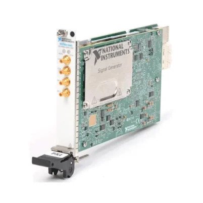
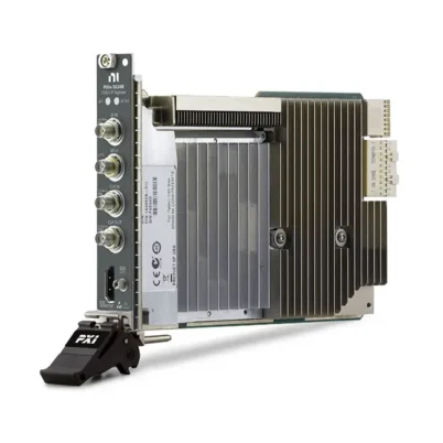
PXI-5661 2.7 GHz PXI Vector Signal Analyzer
The PXI-5661 is a modular PXI vector signal analyzer designed for automated RF testing, spectral monitoring, software-defined radio, modulation analysis and high-throughput signal acquisition. It covers frequencies from 9 kHz to 2.7 GHz and provides as much as 20 MHz of instantaneous bandwidth.
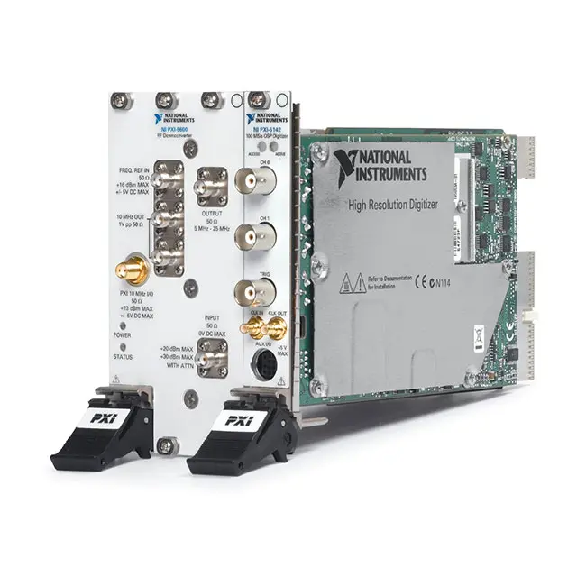
The analyzer combines a PXI-5600 RF downconverter with a PXI-5142 high-resolution digitizer. Incoming RF signals are converted to an intermediate frequency, digitized and processed using an onboard quadrature digital downconverter. This architecture reduces the volume of data transferred to the host while preserving the frequency range required by the measurement.
With a 14-bit digitizer, 256 MB of onboard acquisition memory and software-defined measurement capabilities, the PXI-5661 is suitable for spectrum analysis, time-domain RF capture, vector modulation measurements and automated production testing.
Key Features of the PXI-5661
- 9 kHz to 2.7 GHz frequency range
- 20 MHz maximum instantaneous bandwidth
- Onboard quadrature digital downconverter
- 14-bit, 100 MS/s digitizer architecture
- 256 MB onboard acquisition memory
- -129 dBm/Hz average noise level
- Software-selectable center frequency and reference level
- Spectrum and time-domain waveform acquisition
- I/Q waveform acquisition and analysis
- RF frequency sweeping
- External and PXI trigger support
- 10 MHz reference-clock synchronization
- PXI-5600 RF downconverter
- PXI-5142 IF digitizer
- NI-RFSA instrument-driver support
- Compatible with selected NI RF measurement toolkits
- Suitable for SDR and spectral-monitoring applications
- Compact two-module 3U PXI architecture
PXI-5661 Technical Specifications
| Product Model | PXI-5661 |
|---|---|
| Part Number | 779782-03 |
| Product Type | PXI vector signal analyzer |
| Frequency Range | 9 kHz to 2.7 GHz |
| Maximum Instantaneous Bandwidth | 20 MHz |
| Average Noise Level | -129 dBm/Hz |
| Onboard Memory | 256 MB |
| Digitizer Resolution | 14 bits |
| Digitizer Sample Rate | 100 MS/s |
| Digital Downconverter | Onboard quadrature DDC |
| RF Input Impedance | 50 Ω nominal |
| RF Downconverter Module | PXI-5600 |
| IF Digitizer Module | PXI-5142 |
| Reference Clock | 10 MHz reference synchronization supported |
| Triggering | Software, front-panel and PXI trigger resources |
| Driver | NI-RFSA |
| Module Format | Two 3U PXI modules |
| Life-Cycle Status | Discontinued; verify current service and calibration availability |
PXI-5661 Part Number and System Components
| Item | Model or Part Number | Description |
|---|---|---|
| Complete PXI-5661 System | 779782-03 | 9 kHz to 2.7 GHz PXI vector signal analyzer with 20 MHz instantaneous bandwidth |
| RF Downconverter | PXI-5600 | Converts the selected RF input band to an intermediate-frequency signal |
| IF Digitizer | PXI-5142 | 14-bit, 100 MS/s digitizer with onboard digital downconversion |
| Optional RF Preamplifier | PXI-5690 | External RF preamplifier for applications requiring improved sensitivity |
A complete PXI-5661 requires both the PXI-5600 and PXI-5142 modules, the correct intermodule connections and compatible NI-RFSA software. When purchasing a used or replacement system, verify that both modules and all required RF, IF and reference cables are included.
Two-Module Vector Signal Analyzer Architecture
The PXI-5661 is not a single standalone module. It is a coordinated RF measurement system consisting of the PXI-5600 RF downconverter and PXI-5142 digitizer installed in the same PXI chassis.
The PXI-5600 selects and downconverts the desired RF frequency range. The resulting intermediate-frequency signal is transferred to the PXI-5142, where it is digitized and digitally processed. NI-RFSA presents the coordinated modules to the application as one vector signal analyzer.
Because the system occupies two PXI slots, verify that the chassis has two suitable peripheral or hybrid slots and adequate cooling before installation.
9 kHz to 2.7 GHz Frequency Coverage
The PXI-5661 covers frequencies from 9 kHz through 2.7 GHz. This range supports measurements of low-frequency communication signals, broadcast systems, industrial radio, cellular bands, navigation signals and many other RF applications.
The wide tuning range allows one automated system to perform measurements across multiple frequency bands. Test software can change the center frequency during a sequence without requiring manual adjustments to a conventional benchtop analyzer.
20 MHz Instantaneous Bandwidth
The analyzer provides as much as 20 MHz of instantaneous measurement bandwidth. It can capture a continuous section of RF spectrum around the selected center frequency and return the corresponding time-domain or frequency-domain data.
Instantaneous bandwidth should not be confused with the complete 2.7 GHz tuning range. The analyzer can tune anywhere within its supported frequency range, but it acquires a maximum continuous bandwidth of 20 MHz at one time.
This bandwidth supports many legacy wireless, narrowband and moderate-bandwidth modulation formats. Applications requiring analysis bandwidth greater than 20 MHz should use a newer PXI Express vector signal analyzer or vector signal transceiver.
Onboard Digital Downconversion
The PXI-5142 includes a quadrature digital downconverter that converts the digitized intermediate-frequency signal into baseband I/Q data. The DDC can reduce the sample rate according to the configured measurement bandwidth.
When the application requires only a narrow section of the available spectrum, digital downconversion prevents unnecessary samples from being transferred across the PXI bus. This reduces host-processing requirements, transfer time and stored-data volume.
The DDC architecture is especially useful for continuous signal monitoring, software-defined radio experiments and automated tests requiring rapid acquisition of multiple RF channels.
14-Bit RF Digitization
The PXI-5142 digitizer uses 14-bit analog-to-digital conversion at sample rates up to 100 MS/s. The combination of sample rate and vertical resolution supports detailed time-domain acquisition of the downconverted RF signal.
The digitizer’s 256 MB memory can hold long waveform records or multiple triggered acquisitions. Actual record duration depends on the configured sample rate, number of channels, acquisition mode and data representation.
High-Throughput RF Measurements
The PXI-5661 was designed for software-controlled automated testing. Instead of relying on a manually operated front panel, frequency, reference level, bandwidth, triggering and acquisition settings can be configured programmatically.
Automated control makes it possible to test multiple frequencies, power levels and modulation conditions in one sequence. Measurement results can be stored directly in a database, compared with pass/fail limits or transferred to another application for additional analysis.
Spectrum Measurements
The analyzer can acquire frequency-domain spectra for measuring signal power, occupied bandwidth, harmonics, spurious emissions and interference. NI-RFSA can configure the center frequency, span, reference level and resolution-related acquisition settings.
For wide sweeps exceeding the 20 MHz instantaneous bandwidth, the analyzer tunes across multiple frequency segments. The test application combines the resulting measurements to represent a wider spectrum.
Time-Domain RF Acquisition
The PXI-5661 can return digitized time-domain waveforms for transient analysis and custom signal processing. Engineers can inspect signal envelopes, burst timing, pulse behavior and changes in amplitude or phase over time.
Time-domain acquisition is also useful when an application uses custom demodulation or detection algorithms instead of standard spectrum-analyzer measurements.
I/Q Data Acquisition
Quadrature I/Q data contains the amplitude and phase information required to analyze digitally modulated signals. The PXI-5661 can acquire complex baseband data that is processed using NI software or user-developed algorithms.
I/Q records can be used to calculate error vector magnitude, constellation diagrams, frequency error, phase error, modulation quality and other signal characteristics when paired with compatible analysis software.
RF Sensitivity and Noise Performance
The PXI-5661 has an average noise level specified at -129 dBm/Hz. This performance supports analysis of relatively low-level RF signals when the analyzer is configured with an appropriate reference level and measurement bandwidth.
For applications requiring additional sensitivity, the analyzer can be used with a compatible external RF preamplifier such as the PXI-5690 RF Preamplifier. Adding gain can lower the effective system noise figure, but it also reduces the maximum input level and can affect intermodulation performance.
Phase-Noise Performance
At a 1 GHz carrier and an instantaneous bandwidth of 10 MHz or less, the PXI-5661 maximum specified phase-noise density includes -80 dBc/Hz at a 1 kHz offset, -90 dBc/Hz at 10 kHz, -110 dBc/Hz at 100 kHz and -120 dBc/Hz at a 1 MHz offset.
Phase noise affects measurements close to a strong carrier. When evaluating weak adjacent signals or oscillator performance, select the appropriate acquisition bandwidth and consider the analyzer’s local-oscillator noise contribution.
Triggering and Synchronization
The PXI-5661 supports software, front-panel and PXI backplane triggering. Triggered acquisitions can be synchronized with signal generators, digital instruments and device-under-test control signals.
A shared reference clock can coordinate the analyzer with other RF instruments. This is valuable for phase-coherent measurements, stimulus-response testing and systems containing a separate vector signal generator.
Trigger and reference routing must be configured for the correct PXI-5661 submodule. The RF downconverter and digitizer perform different functions within the combined instrument, so consult the hardware documentation when connecting external trigger or clock signals.
Typical PXI-5661 Applications
- Automated RF production testing
- Vector signal analysis
- Spectrum monitoring
- Software-defined radio development
- RF interference detection
- Wireless device characterization
- Modulation-quality measurements
- Transmitter testing
- RF component validation
- Signal intelligence research
- Aerospace and defense testing
- Communications-system research
- Frequency-domain measurements
- Time-domain RF acquisition
Wireless Transmitter Testing
The PXI-5661 can measure the frequency, power, spectrum and modulation characteristics of compatible wireless transmitters. Automated software can tune across multiple channels and apply pass/fail limits to each measurement.
For vector modulation analysis, use a software toolkit compatible with the PXI-5661 and the applicable wireless standard. Verify that the required signal bandwidth does not exceed the analyzer’s 20 MHz instantaneous bandwidth.
Spectrum Monitoring
The digital downconverter and software-defined architecture make the PXI-5661 suitable for spectrum-monitoring applications. It can tune to specified frequency bands, acquire spectrum or I/Q data and transfer the results to the host for classification or storage.
For continuous monitoring, select the narrowest bandwidth that captures the signal of interest. Lower data rates reduce host transfer requirements and allow longer recording periods.
Software-Defined Radio
In SDR research, the PXI-5661 can serve as a wide-tuning RF receiver. The analyzer converts the selected RF channel into digital I/Q samples that can be processed using custom demodulation, filtering and detection algorithms.
The PXI-5661 is a receiver and measurement instrument rather than a complete transceiver. A separate RF signal generator is required when the system must also generate modulated RF signals.
Automated Production Test
The PXI platform allows the analyzer to operate with switches, signal generators, power supplies and digital instruments in one automated test system. Test software can control every instrument and process results without manual intervention.
When several devices share the analyzer through an RF switch, account for switch insertion loss, isolation and power-handling capability. Calibration or path-loss correction should be applied for every RF route used by the test sequence.
NI-RFSA Software Support
The PXI-5661 is controlled with the NI-RFSA instrument driver. NI-RFSA provides functions for configuring frequency, reference level, acquisition bandwidth, triggering, spectrum measurements and I/Q waveform acquisition.
The driver supports LabVIEW and compatible text-based programming environments. It includes example programs for common operations such as spectrum acquisition, frequency sweeping and waveform reading.
Because the PXI-5661 is a discontinued instrument, verify that the selected NI-RFSA version supports the operating system, PXI controller and analysis software used by the test station.
RF Measurement Toolkit Compatibility
Selected NI RF measurement toolkits can process PXI-5661 waveform data for supported modulation standards. These toolkits may provide measurements such as power, EVM, constellation, occupied bandwidth and spectral emissions.
Compatibility varies by toolkit version, driver release and hardware model. Confirm the complete software compatibility matrix before upgrading an established PXI-5661 system.
PXI-5661 Installation Requirements
Install the PXI-5600 and PXI-5142 in compatible PXI chassis slots with sufficient airflow. Connect the two modules according to the PXI-5661 hardware documentation and avoid bending or placing excessive strain on the coaxial cables.
Install the required NI-RFSA software before configuring the instrument. After the hardware is recognized in NI Measurement & Automation Explorer, run self-test and verify that both physical modules are correctly associated as a PXI-5661 system.
PXI-5661 Troubleshooting
The PXI-5661 is not detected
Confirm that both the PXI-5600 and PXI-5142 are fully installed and recognized in NI MAX. Check chassis power, controller communication, slot compatibility and NI-RFSA installation.
Only one PXI-5661 submodule appears
Inspect the module that is not detected and reseat it after safely powering down the chassis. Verify that the correct device drivers are installed and that both modules appear individually before attempting to configure the combined analyzer.
The analyzer reports a hardware connection error
Check the IF, reference and trigger connections between the PXI-5600 and PXI-5142. Confirm that each cable is connected to the correct front-panel port and that no connector or cable has been damaged.
The measured signal level is incorrect
Verify the reference level, RF attenuation and configured center frequency. Include cable, attenuator, switch and fixture losses in the system correction values. Confirm that the analyzer has completed its warm-up period and that calibration remains valid.
No signal appears in the acquired spectrum
Check the signal source frequency and output power. Confirm that the analyzer is tuned to the correct center frequency and that the measurement span includes the signal. Inspect all RF cables and switching routes.
The acquisition is waiting indefinitely
Review the trigger configuration. The analyzer may be waiting for a digital edge or external event that is not arriving. Use an immediate software trigger during troubleshooting to confirm basic acquisition operation.
Data transfer is too slow
Reduce the requested acquisition bandwidth or record length when the application does not require the full 20 MHz bandwidth. Onboard digital downconversion can reduce the data rate transferred to the host.
The noise floor is higher than expected
Lower the reference level when safe, reduce the measurement bandwidth and inspect the system for external interference. Check cable shielding, grounding and nearby RF transmitters. A preamplifier may help with weak signals but must be used within its linear input range.
The signal is overloaded or distorted
Increase the reference level or add external attenuation. Confirm the peak and average power of the incoming signal, especially for high-crest-factor modulation and pulsed RF signals.
Measurements changed after a software update
Check the NI-RFSA and RF toolkit compatibility matrices. Confirm that measurement settings, correction files and calibration data were preserved during the upgrade. Validated production systems should be tested before deploying new driver versions.
PXI-5661 Comparison with Related Vector Signal Analyzers
| Model | Primary Configuration | Best Suited For |
|---|---|---|
| PXI-5660 | PXI-5600 with legacy PXI-5620 digitizer | Maintaining older PXI RF measurement systems |
| PXI-5661 | 9 kHz to 2.7 GHz, 20 MHz bandwidth | Legacy automated RF and SDR applications |
| PXIe-5663E | 6.6 GHz PXI Express vector signal analyzer | Higher-frequency wireless and automated RF testing |
| PXIe-5665 | Wide-frequency-range, high-dynamic-range VSA | High-performance spectrum and modulation analysis |
| PXIe-5667 | Microwave vector signal analyzer | Higher-frequency RF and microwave measurements |
| PXIe-5668 | High-bandwidth PXI Express vector signal analyzer | Modern wideband wireless, radar and spectrum monitoring |
PXI-5661 vs PXI-5660
The PXI-5660 uses the PXI-5600 downconverter with the older PXI-5620 digitizer. The PXI-5661 replaces the PXI-5620 with the PXI-5142, providing a newer digitizer architecture, greater acquisition capability and improved operating-system support.
Select the PXI-5661 when maintaining a system that requires the 9 kHz lower frequency limit and compatibility with an existing PXI-5600-based RF architecture.
PXI-5661 vs PXIe-5663E
The PXI-5661 covers 9 kHz to 2.7 GHz with 20 MHz instantaneous bandwidth. The PXIe-5663E extends the upper frequency range to 6.6 GHz and uses a PXI Express architecture intended for newer wireless and RF test systems.
The PXI-5661 is useful for legacy applications requiring measurements below 10 MHz. The PXIe-5663E is better suited to higher-frequency applications when its lower frequency limit and software compatibility meet the test requirements.
PXI-5661 vs PXIe-5665
The PXIe-5665 provides higher RF measurement performance, improved dynamic range and wider frequency options compared with the PXI-5661. It is intended for demanding spectrum, phase-noise and modulation measurements.
The PXI-5661 may remain preferable when preserving an existing validated PXI system is more important than obtaining the performance of a newer PXI Express analyzer.
Recommended Related Products
- PXI-5142 14-Bit Digitizer
- PXI-5600 RF Downconverter
- PXI-5690 RF Preamplifier
- PXI-5671 Vector Signal Generator
- PXIe-5663E Vector Signal Analyzer
- PXIe-5665 Vector Signal Analyzer
- PXIe-5667 Microwave Vector Signal Analyzer
- PXIe-5668 Wideband Vector Signal Analyzer
- View More NI PXI and PXI Express Modules
Selecting the Right RF Analyzer
Choose the PXI-5661 when an existing system requires frequency coverage beginning at 9 kHz, an upper frequency of 2.7 GHz and as much as 20 MHz of instantaneous bandwidth. It is particularly relevant for maintaining validated PXI production testers and legacy SDR or spectrum-monitoring platforms.
For new systems, consider a PXI Express vector signal analyzer with a wider frequency range, greater instantaneous bandwidth and active software support. Evaluate frequency coverage, analysis bandwidth, noise floor, dynamic range, phase noise, modulation support and chassis compatibility before selecting a replacement.
Why Choose the PXI-5661?
- Covers RF signals from 9 kHz to 2.7 GHz
- Captures as much as 20 MHz of instantaneous bandwidth
- Provides spectrum, waveform and I/Q acquisition
- Uses onboard digital downconversion to reduce data volume
- Includes a 14-bit, 100 MS/s digitizer architecture
- Provides 256 MB of onboard acquisition memory
- Supports PXI triggers and reference synchronization
- Integrates with NI-RFSA and selected RF toolkits
- Supports automated RF production and validation systems
Frequently Asked Questions
What is the PXI-5661?
The PXI-5661 is a modular PXI vector signal analyzer used for spectrum measurements, I/Q acquisition, modulation analysis and automated RF testing.
What is the PXI-5661 frequency range?
The analyzer covers frequencies from 9 kHz to 2.7 GHz.
What is its maximum instantaneous bandwidth?
The PXI-5661 provides a maximum instantaneous bandwidth of 20 MHz.
Which modules make up the PXI-5661?
The complete analyzer combines a PXI-5600 RF downconverter with a PXI-5142 IF digitizer.
How many PXI slots does the system require?
The PXI-5661 consists of two separate 3U PXI modules and therefore requires two compatible chassis slots.
What is the PXI-5661 part number?
The listed NI part number for the complete PXI-5661 configuration is 779782-03.
How much onboard memory does it have?
The analyzer provides 256 MB of onboard acquisition memory through its digitizer subsystem.
Does the PXI-5661 support I/Q acquisition?
Yes. Its quadrature digital downconverter produces complex I/Q data for vector modulation analysis and custom signal processing.
Can the PXI-5661 be used as a spectrum analyzer?
Yes. It supports frequency-domain spectrum acquisition, swept measurements and related RF power analysis through NI-RFSA and compatible software.
Can it generate RF signals?
No. The PXI-5661 is an RF receiver and analyzer. A separate vector signal generator, such as the PXI-5671, is required to generate RF stimulus.
Which driver controls the PXI-5661?
The analyzer is controlled using the NI-RFSA instrument driver.
Is the PXI-5661 still available from NI?
No. NI identifies the PXI-5661 as no longer available. Used or refurbished systems may remain available, but buyers should verify module completeness, calibration status and software compatibility.
What should be checked before purchasing a used PXI-5661?
Confirm that the package includes both the PXI-5600 and PXI-5142, the necessary intermodule cables, the correct part number and a valid test or calibration record. Also verify compatibility with the intended chassis, controller, operating system and NI-RFSA version.
Request a Quote for the PXI-5661
Contact us for current availability, configuration verification and project pricing for the PXI-5661 2.7 GHz PXI Vector Signal Analyzer. We can also help confirm the included PXI-5600 and PXI-5142 modules, intermodule cables, calibration condition, compatible PXI chassis and related RF measurement hardware.















