






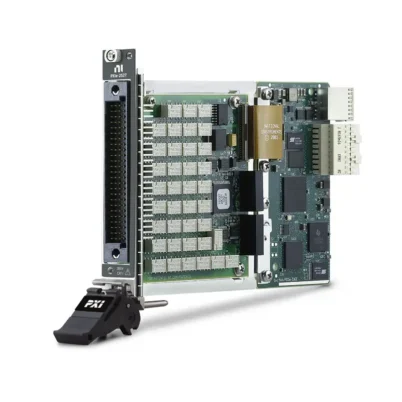
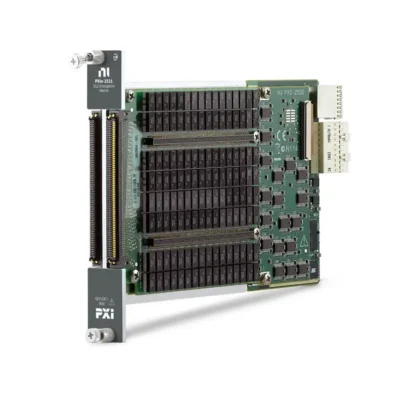
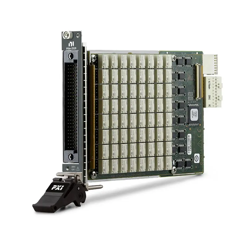
PXIe-2529 128-Crosspoint Matrix Switch Module
The PXIe-2529 is a high-density PXI Express matrix switch module designed for automated test, electronic validation and flexible signal-routing applications. It provides 128 two-wire crosspoints and can be configured as a 4×32, 8×16 or dual 4×16 matrix by selecting the appropriate terminal block.
Featuring electromechanical latching relays, 150 V switching capability and low thermal offset, the PXIe-2529 can route DC and moderate-frequency signals between multiple instruments and devices under test. Hardware triggering, onboard relay counting and NI-SWITCH support help improve test throughput and system maintainability.
Key Features of the PXIe-2529
- 128-crosspoint two-wire matrix switch module
- Configurable 4×32 two-wire matrix topology
- Configurable 8×16 two-wire matrix topology
- Configurable dual 4×16 two-wire matrix topology
- 150 V maximum switching voltage
- 1 A maximum switching current per channel
- 2 A maximum carry current per channel
- 30 W or 37.5 VA maximum switching power
- Greater than 10 MHz typical single-crosspoint bandwidth
- Up to 120 switching cycles per second
- Electromechanical latching relays
- Onboard relay-count monitoring
- PXI hardware trigger support
- 100-pin high-density front connector
PXIe-2529 Technical Specifications
| Product Model | PXIe-2529 |
|---|---|
| Part Number | 780587-29 |
| Product Type | PXI Express Matrix Switch Module |
| Crosspoint Count | 128 |
| Switching Mode | Two-wire |
| Supported Topologies | 4×32, 8×16 and dual 4×16 two-wire matrices |
| Maximum Switching Voltage | 150 V, channel-to-channel or channel-to-ground |
| Maximum Switching Current | 1 A per channel |
| Maximum Carry Current | 2 A per channel |
| Maximum Module Current | 8 A |
| Maximum Switching Power | 30 W or 37.5 VA per channel |
| Initial DC Path Resistance | Less than 1 Ω |
| Thermal EMF | Less than 9 µV |
| Single-Crosspoint Bandwidth | Greater than 10 MHz typical |
| Maximum Scan Rate | 120 cycles/s |
| Relay Operate Time | 4 ms maximum at 20°C |
| Relay Release Time | 4 ms maximum at 20°C |
| Relay Type | Electromechanical, latching |
| Mechanical Relay Life | 50 million cycles |
| Hardware Trigger Sources | PXI trigger lines 0 through 7 |
| Front Connector | 100-pin high-density interconnect |
| Operating Temperature | 0°C to 55°C |
| Dimensions | 3U, one-slot PXI Express module |
| Weight | 410 g |
| Bus Interface | PXI Express |
PXIe-2529 Part Number and Terminal Blocks
| Item | Part Number | Configuration |
|---|---|---|
| PXIe-2529 | 780587-29 | 128-crosspoint, two-wire PXI Express matrix switch module |
| TB-2634 | 778840-01 | 4×32 two-wire matrix terminal block |
| TB-2635 | 778839-01 | 8×16 two-wire matrix terminal block |
| TB-2636 | 196762-01 | Dual 4×16 two-wire matrix terminal block |
The selected terminal block determines the matrix topology available to the application. Terminal blocks should be ordered separately unless specifically included in the quotation.
When using the TB-2634 with the PXIe-2529, review the accessory installation requirements carefully because an additional third-party ribbon cable may be required and is not supplied by NI.
Flexible Matrix Signal Routing
Unlike a multiplexer that normally connects one selected channel to a common terminal, a matrix switch allows connections between multiple rows and columns. This architecture provides greater flexibility when several instruments must communicate with multiple devices or test points.
Each crosspoint connects a two-wire row pair to a two-wire column pair. Application software can create, modify and disconnect signal routes as the test sequence progresses.
4×32 Two-Wire Matrix Topology
When used with the TB-2634 terminal block, the PXIe-2529 operates as a 4×32 two-wire matrix. This topology allows four instrument connections to access as many as 32 devices, test points or signal pairs.
The 4×32 configuration is suitable when a small group of measurement instruments must be dynamically connected to a larger number of test channels.
8×16 Two-Wire Matrix Topology
The TB-2635 configures the module as an 8×16 two-wire matrix. This arrangement provides more row connections for instruments while reducing the number of available column connections.
It is useful for systems that need to route several measurement or stimulus instruments to as many as 16 device connections.
Dual 4×16 Two-Wire Matrix Topology
The dual 4×16 configuration separates the available crosspoints into two independently controlled matrix banks. This topology can support two separate test sections or devices without connecting their signal paths together.
The dual-bank architecture is useful for parallel test stations, isolated subsystems and applications requiring independent routing groups within one PXI Express slot.
150 V Signal Switching
The PXIe-2529 supports switching voltages up to 150 V between channels or between a channel and ground. It can switch up to 1 A and carry up to 2 A per channel, subject to the module’s total current and switching-power limits.
The voltage, current and power ratings must be evaluated together. A signal within the voltage limit may still exceed the module rating if its current or switching power is too high.
Measurement Category I Operation
The PXIe-2529 is designed for Measurement Category I signal applications. It should not be connected directly to building mains, wall outlets or circuits classified as Measurement Categories II, III or IV.
When hazardous voltages are present, follow the isolation, cabling and terminal-access requirements specified for the module and selected terminal block.
Low Thermal EMF for Accurate Measurements
Thermal EMF below 9 µV helps reduce voltage offsets introduced by the switch path. This characteristic is useful when routing low-level voltage signals to a precision digital multimeter or data acquisition instrument.
Overall measurement accuracy also depends on the connected instrument, cable construction, terminal block, grounding method, temperature gradients and signal-settling time.
Path Resistance Considerations
The combined high and low signal path has an initial DC resistance below 1 Ω. Relay and trace resistance should be considered when routing current or performing resistance measurements.
For low-resistance measurements, a four-wire measurement architecture may provide better accuracy because it reduces errors caused by switch, fixture and cable resistance.
Electromechanical Latching Relays
The PXIe-2529 uses electromechanical latching relays with silver-palladium and gold contacts. Latching relays maintain their selected state without requiring continuous coil power.
The relays provide a mechanical life of up to 50 million cycles under specified conditions. Relay life under load depends on switching voltage, current, load type and switching frequency.
Onboard Relay Counting
Onboard relay counting records the number of operations performed by individual relays. Test engineers can use this information to identify heavily used crosspoints and plan maintenance before a relay affects test-system performance.
The PXIe-2529 relays are field replaceable, helping extend the operational life of systems used in production and laboratory environments.
Hardware Triggering and Deterministic Operation
The module supports input and output triggering through PXI trigger lines 0 through 7. Hardware triggering can coordinate switch operations with digital multimeters, digitizers and other PXI instruments without relying entirely on software timing.
This deterministic operation is useful for automated tests that require repeatable routing sequences and synchronized measurements.
Typical PXIe-2529 Applications
- Automated electronic device testing
- Production and manufacturing test systems
- Multiple-instrument signal routing
- Printed circuit board functional testing
- Semiconductor device validation
- Battery and power-system testing
- Sensor and transducer test systems
- Data acquisition signal routing
- Design verification and characterization
- Research and laboratory automation
Automated Instrument-to-DUT Routing
The PXIe-2529 can connect multiple measurement instruments to different test points without manually changing cables. For example, rows can be connected to a digital multimeter, source measurement unit or data acquisition device, while columns connect to the device under test.
A PXIe-4080 digital multimeter can be integrated with the matrix to perform automated voltage, current or resistance measurements across multiple test points.
NI-SWITCH Software Support
The PXIe-2529 is controlled using the NI-SWITCH instrument driver. NI-SWITCH provides functions for selecting a topology, connecting crosspoints, disconnecting routes, configuring scan lists, managing triggers and reading relay-count information.
The driver can be used with LabVIEW, LabWindows/CVI and supported text-based programming environments.
NI Switch Executive Integration
NI Switch Executive allows engineers to define matrix routes using meaningful signal and route names. This can simplify software development when the PXIe-2529 is used with multiple switch modules or complex test fixtures.
Named routes make test sequences easier to understand and maintain because application code does not need to manage every physical relay connection directly.
PXI Express System Integration
The PXIe-2529 occupies one slot in a compatible PXI Express chassis. It can be combined with digital multimeters, source measurement units, digitizers, power supplies and other PXI instruments to build an integrated automated test platform.
Before installation, verify chassis slot compatibility, cooling capacity, terminal-block clearance and the NI-SWITCH version supported by the controller and operating system.
PXIe-2529 Troubleshooting
The module is not detected in NI MAX
Confirm that the PXIe-2529 is fully installed in a compatible PXI Express slot. Check chassis power, controller communication and NI-SWITCH installation, then restart NI Measurement & Automation Explorer.
The expected matrix topology is unavailable
Verify that the correct terminal block is installed and that the matching topology is selected in NI-SWITCH. The TB-2634, TB-2635 and TB-2636 provide different matrix configurations.
A row cannot connect to a column
Check the route names, terminal-block wiring and selected topology. Confirm that another route has not created an electrical conflict and review the relay count for the affected crosspoint.
Measurements show an unexpected voltage offset
Allow sufficient settling time after switching and check for temperature gradients across connectors and terminals. Review shielding, grounding, cable routing and the offset specifications of the connected measurement instrument.
The scan rate is lower than expected
Review relay settling time, trigger configuration, instrument measurement time and software overhead. The complete system throughput depends on both switch operation and the measurement instrument’s acquisition settings.
A relay does not change state
Run a self-test in NI MAX, inspect the terminal-block connection and review the relay count. If the relay has reached the end of its service life, it may require field replacement or module service.
PXIe-2529 Comparison
| Model | Matrix Configuration | Best Suited For |
|---|---|---|
| PXIe-2529 | 4×32, 8×16 or dual 4×16 two-wire | Flexible 150 V matrix routing with 128 crosspoints |
| PXI-2529 | Similar 128-crosspoint matrix configurations | Legacy PXI and PXI hybrid-slot systems |
| PXIe-2532B | Higher-density configurable matrix | Systems requiring substantially more crosspoints |
| PXIe-2737 | 4×64 matrix | Applications requiring additional column connections |
| PXIe-2738 | 8×32 matrix | Balanced instrument and DUT connection counts |
| PXIe-2739 | 16×16 matrix | Systems requiring an equal number of rows and columns |
Recommended Related Products
- PXI-2529 Matrix Switch Module
- PXIe-2532B High-Density Matrix Switch Module
- PXIe-2737 4×64 Matrix Switch Module
- PXIe-2738 8×32 Matrix Switch Module
- PXIe-2739 16×16 Matrix Switch Module
- PXIe-4080 Digital Multimeter
- View More NI PXI and PXI Express Modules
Selecting the Right PXIe-2529 Topology
Select the 4×32 topology when a small number of instruments must access many test points. Choose the 8×16 topology when the system needs more instrument-side connections and fewer DUT-side connections.
Choose the dual 4×16 configuration when two independent routing groups are required. The topology should be selected before ordering because it determines the required terminal block and external wiring arrangement.
PXIe-2529 vs PXI-2529
The PXIe-2529 and PXI-2529 provide similar 128-crosspoint, two-wire matrix functionality. The primary difference is the chassis interface: the PXIe-2529 uses a PXI Express connection, while the PXI-2529 uses a PXI hybrid-compatible interface.
Choose the PXIe-2529 for current PXI Express systems. The PXI-2529 may be appropriate when maintaining an existing PXI system with compatible hybrid slots.
Why Choose the PXIe-2529?
- Provides 128 two-wire matrix crosspoints in one PXI Express slot
- Supports three matrix configurations through interchangeable terminal blocks
- Routes signals up to 150 V and 1 A
- Offers low thermal EMF for accurate voltage measurements
- Supports deterministic hardware-triggered operation
- Includes relay-count monitoring for preventive maintenance
- Integrates with NI-SWITCH and NI Switch Executive
Frequently Asked Questions
What is the PXIe-2529?
The PXIe-2529 is a 128-crosspoint, two-wire PXI Express matrix switch module used to create programmable connections between multiple instruments and devices under test.
Which topologies does the PXIe-2529 support?
It supports 4×32, 8×16 and dual 4×16 two-wire matrix topologies. The installed terminal block determines the available configuration.
Which terminal block is required?
Use the TB-2634 for a 4×32 matrix, the TB-2635 for an 8×16 matrix or the TB-2636 for a dual 4×16 matrix.
What is the maximum switching voltage?
The maximum switching voltage is 150 V between channels or between a channel and ground for Measurement Category I applications.
What is the maximum switching current?
The PXIe-2529 can switch up to 1 A per channel and carry up to 2 A per channel. Maximum switching power is 30 W or 37.5 VA per channel.
What is the PXIe-2529 bandwidth?
The module provides greater than 10 MHz typical bandwidth through a single crosspoint in a 50 Ω system.
Does the PXIe-2529 support hardware triggering?
Yes. It supports input and output triggering through PXI trigger lines 0 through 7 for deterministic switching and instrument synchronization.
Can the PXIe-2529 relays be replaced?
Yes. The electromechanical relays are field replaceable. Relay-count information can help identify relays approaching the end of their useful life.
What is the part number for the PXIe-2529?
The standard NI part number for the PXIe-2529 is 780587-29.
Request a Quote for the PXIe-2529
Contact us for current availability, lead time and project pricing for the PXIe-2529 128-Crosspoint Matrix Switch Module. We can also help identify the correct TB-2634, TB-2635 or TB-2636 terminal block, PXI Express chassis and measurement instruments for your test system.















