






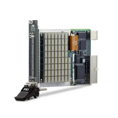
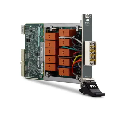
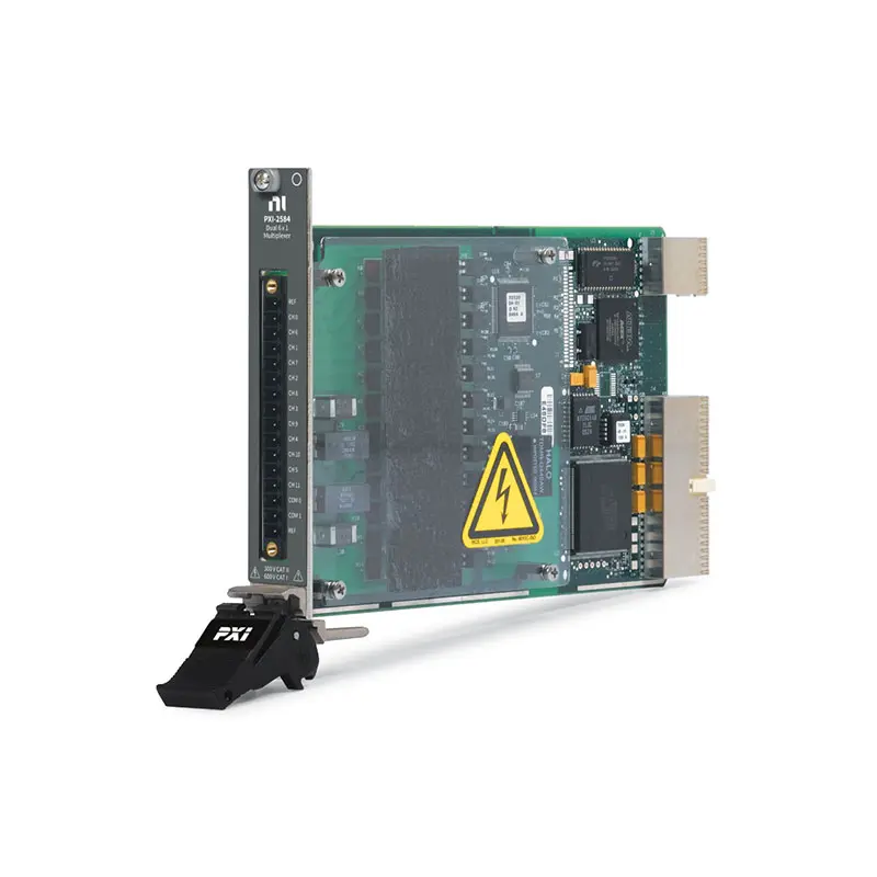
PXI-2584 12-Channel 600 V PXI Multiplexer Switch Module
The PXI-2584 is a high-voltage PXI multiplexer switch module designed for battery-stack testing, fuel-cell measurements, automated test equipment and other high-voltage, low-current signal-routing applications. It supports 1-wire, 2-wire and user-implemented interleaved configurations.
The module can route signals up to 600 VDC or 600 VAC peak in Measurement Category I applications and up to 300 V in Measurement Category II applications. Its reed relays provide fast 0.4 ms typical operation, 600-channel-per-second scanning and long mechanical life.
Key Features of the PXI-2584
- 12-channel high-voltage PXI multiplexer
- Dual 6 × 1, 1-wire topology
- 12 × 1, 1-wire topology
- 6 × 1, 2-wire topology
- User-implemented interleaved battery-stack topology
- Up to 11 interleaved 2-wire measurement channels
- 600 V CAT I and 300 V CAT II capability
- 0.5 A maximum switching and carry current
- 10 W maximum switching power per channel
- 900 kHz or greater typical bandwidth
- 600 channels/s maximum scan rate
- 0.4 ms typical relay operate time
- Rhodium-contact reed relays
- 32,000-step deterministic scan list
- Onboard relay-count tracking
- PXI hardware trigger support
- 16-position MINI-COMBICON connector
- NI-SWITCH and NI Switch Executive support
PXI-2584 Technical Specifications
| Product Model | PXI-2584 |
|---|---|
| Part Number | 778572-84 |
| Product Type | High-voltage PXI multiplexer switch module |
| Advertised Channel Count | 12 channels |
| Supported Wire Modes | 1-wire and 2-wire |
| Standard Topologies | Dual 6 × 1, 1-wire; 12 × 1, 1-wire; 6 × 1, 2-wire; independent |
| Interleaved Configuration | Up to 11 × 1, 2-wire for stacked battery or fuel-cell measurements |
| Maximum Switching Voltage | 600 VDC or 600 VAC peak, subject to measurement-category limits |
| Safety Rating | 300 V CAT II or 600 V CAT I |
| Maximum Switching Current | 0.5 A per channel or common |
| Maximum Carry Current | 0.5 A per channel or common |
| Maximum Switching Power | 10 W per channel |
| Minimum Switching Capacity | 0.5 V or 1 mA |
| Initial DC Path Resistance | 1.1 Ω or less for a 1-wire path |
| End-of-Life Path Resistance | Greater than 2 Ω |
| Typical Thermal EMF | Less than 50 µV for a 1-wire channel-to-common path |
| Typical Bandwidth | 900 kHz or greater with 50 Ω termination |
| Typical DC Open-Channel Isolation | Greater than 1 × 10¹¹ Ω |
| Maximum Scan Rate | 600 channels/s |
| Typical Relay Operate Time | 0.4 ms |
| Maximum Relay Operate Time | 0.81 ms |
| Mechanical Relay Life | 3 × 10⁸ cycles at 1 V, 10 mA resistive |
| Relay Type | Reed relay |
| Relay Contact Material | Rhodium |
| Scan-List Capacity | Up to 32,000 connections |
| I/O Connector | 16-position MINI-COMBICON plug |
| Bus Interface | PXI hybrid |
| Module Format | 3U, one-slot PXI module |
| Operating Temperature | 0°C to 55°C |
| Storage Temperature | −20°C to 70°C |
| Relative Humidity | 5% to 85%, noncondensing |
| Maximum Altitude | 2,000 m |
| Software Support | NI-SWITCH and NI Switch Executive |
PXI-2584 Part Number and Accessories
| Item | Part Number | Description |
|---|---|---|
| PXI-2584 | 778572-84 | 12-channel, 600 V high-voltage PXI multiplexer module |
| PXI-2584 Connector and Backshell Kit | 779168-02 | Mating connector and protective backshell for custom PXI-2584 wiring |
The PXI-2584 uses a specialized 16-position MINI-COMBICON front-panel connection. NI lists the Connector and Backshell Kit, part number 779168-02, as the custom-connectivity option. Verify the connector, backshell, wire insulation, voltage rating and strain relief before building a high-voltage fixture.
Configurable High-Voltage Multiplexer
The PXI-2584 combines several multiplexer configurations in one module. Software can select a dual 6 × 1, 1-wire topology, a single 12 × 1, 1-wire topology, a 6 × 1, 2-wire topology or an independent-relay configuration.
The correct topology depends on whether the application switches a single conductor, switches both sides of a differential signal or measures a series-connected battery or fuel-cell stack.
Dual 6 × 1, 1-Wire Topology
In the dual 6 × 1 configuration, the PXI-2584 operates as two independent one-wire multiplexer banks. Each bank connects one of six channels to its corresponding common terminal.
This mode allows two instruments or two independent groups of signals to be switched through the same PXI module. The two banks can be controlled separately according to the test sequence.
12 × 1, 1-Wire Topology
The 12 × 1 topology combines the available channels into one one-wire multiplexer. It connects one of 12 input channels to a shared common terminal.
This configuration provides the module’s full standard channel count and is useful when signals share a suitable reference or when only one conductor must be switched.
6 × 1, 2-Wire Topology
The 2-wire 6 × 1 topology switches two conductors for every selected channel. It is appropriate for differential voltage measurements and applications in which both the high and low signal connections must be routed.
Because two relays are used for each measurement channel, the standard differential configuration provides six channels rather than 12 one-wire channels.
Independent Relay Topology
Independent mode provides software access to the PXI-2584 relay connections without imposing one of the predefined multiplexer routes. This mode supports specialized routing and user-implemented interleaved operation.
Independent control requires careful route management. Software and fixture wiring must prevent incompatible stack potentials or measurement points from being connected together.
Interleaved Battery-Stack Topology
The PXI-2584 can be configured as a user-implemented interleaved multiplexer for measuring series-connected cells. Instead of assigning two separate switch wires to every cell, adjacent voltage-measurement channels share the connection between neighboring cells.
This method can increase differential measurement capacity from six standard 2-wire channels to as many as 11 interleaved channels. It is particularly useful for battery stacks, fuel-cell stacks and other series-connected voltage sources.
Measuring Battery and Fuel-Cell Stacks
In a stacked system, each measurement point may be at a different common-mode voltage relative to ground. The PXI-2584’s high-voltage isolation allows an appropriately rated measurement instrument to be switched across individual cells or sections of the stack.
The voltage between the selected points, channel-to-ground voltage and total stack voltage must remain within the ratings of the switch module, measuring instrument, connector and test fixture.
300 V CAT II and 600 V CAT I Ratings
The PXI-2584 is rated for signals up to 300 V in Measurement Category II applications and up to 600 V in Measurement Category I applications. Measurement category describes the transient environment in which the circuit is used and is not interchangeable with a simple voltage rating.
CAT I applies to protected measurement circuits that are not directly connected to building mains. CAT II applies to certain circuits connected to low-voltage mains installations. The complete system must follow the lowest applicable voltage and measurement-category rating of any connected component.
0.5 A Switching and Carry Current
The module can switch or carry up to 0.5 A through each channel or common connection. It is intended primarily for high-voltage, low-current signals rather than high-power battery charge or discharge paths.
Do not route traction current, battery charging current or other high-current power paths through the PXI-2584. Use the module for measurement and low-power stimulus signals within its current and power limits.
10 W Maximum Switching Power
Maximum switching power is 10 W per channel. A signal must remain within the voltage, current and power ratings simultaneously.
For example, the full 0.5 A current rating cannot be switched at 600 V because that would greatly exceed the 10 W power limit. At higher voltages, the permissible switched current is correspondingly lower.
Reed Relay Switching
The PXI-2584 uses reed relays with rhodium contacts. Reed relays provide fast operation, high isolation and long mechanical life in low-current signal-routing applications.
Relay life depends on voltage, current, switched energy, load type and switching frequency. Capacitive and inductive loads can place substantially more stress on the contacts than a steady resistive load.
Relay Life
The specified mechanical life is 300 million cycles at a 1 V, 10 mA resistive load. Electrical life decreases when the module switches high-voltage capacitive signals or other demanding loads.
NI specifies approximately 18 million cycles for a 600 V, 7 mA, 90 pF capacitive load and approximately 7 million cycles for a 600 V, 16.5 mA, 90 pF capacitive load. Actual life depends on the application waveform and operating conditions.
Fast 0.4 ms Relay Operation
Typical relay operate time is 0.4 ms, with a specified maximum of 0.81 ms. Fast actuation helps the PXI-2584 achieve a scan rate of up to 600 channels per second.
Some measurement systems need additional settling time after a channel changes. High source impedance, cable capacitance, filtering and instrument input characteristics can all increase the required delay.
600-Channel-per-Second Scanning
The PXI-2584 supports automatic scanning at up to 600 channels per second. A scan list can contain as many as 32,000 connections, allowing the module to sequence through many measurements without continuous intervention from the host processor.
Actual completed-measurement throughput also depends on the measuring instrument, trigger sequence, integration time and settling requirements of the connected signal.
Hardware Triggering
PXI hardware triggering allows switch operations to be synchronized with digital multimeters, digitizers and other PXI instruments. The measuring instrument can trigger the switch after completing a measurement, and the switch can signal when the next route is ready.
This deterministic coordination reduces software timing overhead and is useful for automated battery-stack and production test systems.
Relay-Count Tracking
The PXI-2584 records relay operation counts onboard the module. These counts can be read programmatically and used to identify heavily used channels or plan preventive maintenance.
Relay-count data is particularly valuable in production systems that run long scan sequences and repeatedly use the same measurement paths.
REF Connections
The module provides reference connections that can help reduce noise and preserve signal integrity in one-wire topologies. The appropriate REF wiring depends on the signal source, measurement instrument and grounding arrangement.
Before connecting the reference terminals, review the potential difference between the test system, chassis ground and device under test. Incorrect grounding can create unwanted current paths or exceed an isolation rating.
Typical PXI-2584 Applications
- Battery-cell voltage measurement
- Battery-stack monitoring
- Fuel-cell stack testing
- Energy-storage system validation
- High-voltage component testing
- Power electronics validation
- Electric-vehicle battery testing
- High-voltage automated test equipment
- Insulation and leakage test routing
- Production functional testing
- Laboratory automation
- Multichannel high-voltage measurement
Electric-Vehicle Battery Testing
The PXI-2584 can route individual cell or module voltages to an appropriately rated digital multimeter. Automated software can scan the stack and compare cell voltages under different operating conditions.
The module is not a battery-management system and must not be used as a protective disconnect. The fixture should include suitable fusing, insulation, interlocks and discharge procedures.
Fuel-Cell Test Systems
Fuel-cell stacks contain multiple series-connected cells whose individual voltages must be monitored. The interleaved topology allows the PXI-2584 to increase the number of differential measurements available from one module.
Multiple modules can be used when a stack contains more measurement points than one PXI-2584 can accommodate. System designers must maintain appropriate isolation between modules, instruments and stack sections.
High-Voltage Digital Multimeter Integration
The PXI-2584 can be paired with a high-voltage PXI digital multimeter for automated voltage measurements. The switch selects a cell or test point, allows the path to settle and then triggers the DMM to acquire a reading.
The DMM must support the expected differential voltage, common-mode voltage and measurement category. The switch module’s rating does not increase the safety rating of the connected instrument.
NI-SWITCH Software Support
The PXI-2584 is controlled through the NI-SWITCH instrument driver. NI-SWITCH provides functions for selecting the topology, opening and closing routes, configuring scan lists, routing triggers and reading relay-count information.
The driver supports LabVIEW, LabWindows/CVI and compatible text-based programming environments. Interleaved functionality is implemented by selecting independent mode and controlling the required relay sequence in software.
NI Switch Executive Integration
NI Switch Executive allows developers to assign descriptive names to channels, signals and routes. This can make a battery-stack test program easier to read than one that directly addresses physical relay names.
Named routes also simplify systems containing multiple PXI-2584 modules, DMMs and custom high-voltage fixtures.
PXI Chassis Integration
The PXI-2584 occupies one slot in a compatible 3U PXI chassis or PXI Express chassis hybrid slot. It can operate alongside digital multimeters, data acquisition modules, power supplies and other modular instruments.
Turn off the chassis and safely discharge the connected high-voltage system before installing, removing or rewiring the module. Verify adequate connector clearance and strain relief before closing the test enclosure.
High-Voltage Safety Considerations
Potentially hazardous voltages require insulated wiring, suitable enclosures, protective earth connections, interlocks and appropriate personal protective equipment. Only qualified personnel should assemble or service the test fixture.
Wire insulation, connector spacing, terminal covers and the measuring instrument must be rated for the maximum voltage and measurement category. Never assume that a component is suitable based only on its nominal voltage rating.
PXI-2584 Troubleshooting
The PXI-2584 is not detected in NI MAX
Confirm that the module is fully installed in a compatible PXI or PXI Express hybrid slot. Check chassis power, controller communication and NI-SWITCH installation, then rescan the system in NI Measurement & Automation Explorer.
A channel does not connect to the common terminal
Verify that the selected NI-SWITCH topology matches the fixture wiring. Check the channel name, common connection, connector pins and external continuity after safely disconnecting and discharging the high-voltage source.
Battery-cell readings are assigned to the wrong channels
Review the physical order of the stack connections and the software relay sequence. Interleaved operation requires adjacent measurement points to be wired and addressed in the correct order.
Measurements are noisy or unstable
Check the REF connection, shielding, grounding, source impedance and settling time. Keep high-current battery cables separated from low-current measurement wiring.
The scan rate is lower than expected
Review the DMM integration time, channel settling delay, trigger configuration and software sequence. The 600-channel-per-second rating does not include every measurement and stabilization delay in a complete test system.
Path resistance has increased
Disconnect and safely discharge the test system before checking the cable, connector and relay path. A path resistance that rises rapidly above the specified initial value can indicate relay wear or a degraded external connection.
Relay life is shorter than expected
Review the switched voltage, current, capacitance and load type. High-voltage capacitive loads and inductive transients can reduce electrical relay life even when steady-state current appears low.
The connector becomes warm
Stop the test and safely remove the high-voltage source. Inspect terminal torque, conductor size, contact condition and current. Do not operate the system until the cause has been identified.
PXI-2584 Comparison with Similar Multiplexer Modules
| Model | Primary Configuration | Best Suited For |
|---|---|---|
| PXI-2584 | 12 channels, 600 V, 0.5 A, reed relays | Battery-stack, fuel-cell and high-voltage measurements |
| PXI-2527 | 32-channel, 2-wire, 300 V multiplexer | Higher channel counts at lower maximum voltage |
| PXI-2575 | High-density multiplexer, up to 196 one-wire channels | Large low-to-medium-voltage measurement systems |
| PXI-2576 | Multibank 2-wire multiplexer | Parallel low-channel-count measurement groups |
| PXI-2585 | 10 × 1 multiplexer, 300 V, 12 A | High-current multiplexer applications |
PXI-2584 vs PXI-2527
The PXI-2584 supports voltage up to 600 V in CAT I applications but provides fewer standard differential channels and a maximum current of 0.5 A. The PXI-2527 provides a higher channel count and supports 2 A switching, but its maximum voltage is lower.
Choose the PXI-2584 for battery stacks, fuel cells and other applications requiring 600 V isolation. Choose the PXI-2527 when more channels or higher current is required within its lower voltage rating.
PXI-2584 vs PXI-2585
The PXI-2584 is optimized for high-voltage, low-current measurements and supports up to 600 V at a maximum of 0.5 A and 10 W. The PXI-2585 provides a 10 × 1 topology and supports substantially higher current up to 12 A, but its maximum voltage is lower.
Select the PXI-2584 for cell-voltage measurement and other sensitive high-voltage signals. Select the PXI-2585 for high-current loads that remain within its voltage, power and connector ratings.
Recommended Related Products
- PXI-2527 32-Channel 300 V Multiplexer Switch Module
- PXI-2575 High-Density Multiplexer Switch Module
- PXI-2576 Multibank Multiplexer Switch Module
- PXI-2585 10-Channel High-Current Multiplexer
- PXIe-4081 7½-Digit Digital Multimeter
- View More NI PXI and PXI Express Modules
Selecting the Right PXI Multiplexer
Choose the PXI-2584 when the application requires battery-stack or fuel-cell measurements, 600 V CAT I isolation, interleaved differential measurement and fast reed-relay scanning. It is designed for high-voltage signals whose current and switching power remain relatively low.
Consider the PXI-2527 when additional 2-wire channels are required at up to 300 V. Select the PXI-2575 for substantially higher channel density, or the PXI-2585 when load current is more important than maximum voltage.
Why Choose the PXI-2584?
- Routes signals up to 600 V in CAT I applications
- Supports 300 V CAT II measurement environments
- Provides four software-selectable operation modes
- Supports interleaved battery-stack measurements
- Scans at up to 600 channels per second
- Uses fast, long-life rhodium-contact reed relays
- Includes onboard relay-count tracking
- Supports 32,000-step deterministic scan lists
- Synchronizes with PXI instruments through hardware triggers
- Integrates with NI-SWITCH and NI Switch Executive
Frequently Asked Questions
What is the PXI-2584?
The PXI-2584 is a 12-channel, high-voltage PXI multiplexer switch module designed for battery stacks, fuel cells and automated high-voltage measurements.
What topologies does the PXI-2584 support?
It supports dual 6 × 1, 1-wire; 12 × 1, 1-wire; 6 × 1, 2-wire; and independent topologies. Independent control can be used to implement an interleaved battery-stack configuration.
What is the maximum switching voltage?
The module supports up to 600 VDC or 600 VAC peak in CAT I applications and up to 300 V in CAT II applications, subject to the detailed safety limitations.
What is the maximum current?
Maximum switching or carry current is 0.5 A per channel or common connection.
Can the PXI-2584 switch 0.5 A at 600 V?
No. Maximum switching power is 10 W, so voltage, current and power limits must be observed simultaneously. The permissible current at 600 V is much lower than 0.5 A.
How many battery-cell measurements can one module support?
The standard 2-wire topology provides six channels. A correctly implemented interleaved topology can provide up to 11 differential battery-stack measurement channels.
What is the bandwidth of the PXI-2584?
Typical −3 dB bandwidth is at least 900 kHz with 50 Ω termination.
What is the maximum scan rate?
The module supports scanning at up to 600 channels per second, subject to signal and measurement settling requirements.
Which connector is required?
The module uses a 16-position MINI-COMBICON connection. NI lists the Connector and Backshell Kit, part number 779168-02, for custom connectivity.
Does the PXI-2584 support relay-count tracking?
Yes. Onboard relay counts can be read programmatically for usage monitoring and preventive maintenance.
Which software controls the PXI-2584?
The module is controlled through NI-SWITCH and can be incorporated into named-route systems using NI Switch Executive.
What is the PXI-2584 part number?
The standard NI part number is 778572-84.
Request a Quote for the PXI-2584
Contact us for current availability, lead time and project pricing for the PXI-2584 12-Channel 600 V PXI Multiplexer Switch Module. We can also help identify the 779168-02 connector and backshell kit, compatible PXI digital multimeters, PXI chassis and alternative NI high-voltage switch modules for your battery or fuel-cell test system.















