






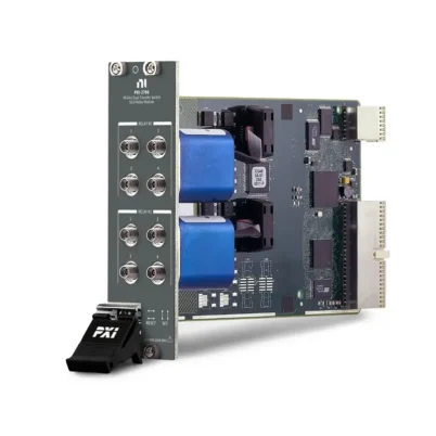

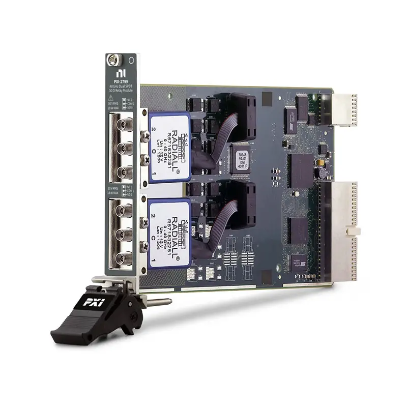
PXI-2799 40 GHz Dual SPDT PXI RF Relay Module
The PXI-2799 is a high-frequency PXI RF relay module designed for automated microwave signal routing, RF component testing and modular test-system integration. It provides two independently controlled single-pole double-throw (SPDT) relay banks with a frequency range extending from DC to 40 GHz.
Each SPDT bank connects one common port to either of two selectable RF paths. The module combines 50 Ω impedance, less than 0.8 dB insertion loss at up to 40 GHz, high isolation and six front-panel 2.92 mm RF connectors. It is suitable for source selection, receiver routing, calibration-path switching, high-order harmonic measurements and automated RF validation.
Key Features of the PXI-2799
- Two independent SPDT RF relay banks
- DC to 40 GHz switching bandwidth
- 50 Ω characteristic impedance
- Less than 0.8 dB insertion loss at up to 40 GHz
- Greater than 50 dB open-channel isolation at up to 40 GHz
- Less than 1.9 VSWR at up to 40 GHz
- 18 W maximum RF carry power through 26.5 GHz
- 10 W maximum RF carry power through 40 GHz
- 0.6 Arms maximum carry current per channel
- 30 VAC maximum switching voltage
- Electromechanical latching relays
- 10 ms relay operate and release time
- 1 × 10⁷ cycles expected mechanical relay life
- Onboard relay-count tracking
- Six female 2.92 mm RF connectors
- PXI hardware trigger support
- PXI hybrid-slot compatibility
- NI-SWITCH and NI Switch Executive support
PXI-2799 Technical Specifications
| Product Model | PXI-2799 |
|---|---|
| Part Number | 782359-01 |
| Product Type | PXI RF and microwave relay module |
| Relay Configuration | Dual SPDT |
| Number of Banks | 2 independent banks |
| Frequency Range | DC to 40 GHz |
| Characteristic Impedance | 50 Ω nominal |
| Insertion Loss at 6 GHz | Less than 0.3 dB |
| Insertion Loss at 12.4 GHz | Less than 0.4 dB |
| Insertion Loss at 18 GHz | Less than 0.5 dB |
| Insertion Loss at 26.5 GHz | Less than 0.7 dB |
| Insertion Loss at 40 GHz | Less than 0.8 dB |
| VSWR at 40 GHz | Less than 1.9 |
| Open-Channel Isolation at 40 GHz | Greater than 50 dB |
| Maximum RF Carry Power to 26.5 GHz | 18 W into a 50 Ω load |
| Maximum RF Carry Power to 40 GHz | 10 W into a 50 Ω load |
| Maximum Carry Current | 0.6 Arms per channel |
| Maximum Switching Voltage | 30 VAC |
| Relay Type | Electromechanical, latching |
| Relay Manufacturer Series | Radiall R571 series |
| Contact Material | Gold-plated beryllium copper |
| Relay Operate and Release Time | 10 ms |
| Expected Mechanical Relay Life | 1 × 10⁷ cycles |
| Insertion-Loss Repeatability | Less than 0.03 dB typical |
| Scan Rate | 2 cycles/s |
| Input Trigger Sources | PXI trigger lines 0 through 7 |
| Output Trigger Destinations | PXI trigger lines 0 through 7 |
| Minimum Input Trigger Pulse Width | 150 ns with digital filtering enabled |
| Front-Panel Connectors | 6 × female 2.92 mm RF jacks |
| Recommended Connector Torque | 0.8 to 1.1 N·m, or 7 to 10 in-lb |
| Bus Interface | PXI hybrid |
| Module Size | 3U, one-slot PXI/cPCI module |
| Dimensions | 21.6 × 2.0 × 13.0 cm |
| Weight | 229 g |
| Operating Temperature | 0°C to 55°C |
| Storage Temperature | −20°C to 70°C |
| Operating Humidity | 5% to 85%, noncondensing |
| Maximum Operating Altitude | 2,000 m |
| Software Support | NI-SWITCH and NI Switch Executive |
PXI-2799 RF Performance
| Frequency | Maximum Insertion Loss | Maximum VSWR | Minimum Open-Channel Isolation |
|---|---|---|---|
| Up to 6 GHz | 0.3 dB | 1.3 | 70 dB |
| Up to 12.4 GHz | 0.4 dB | 1.4 | 60 dB |
| Up to 18 GHz | 0.5 dB | 1.5 | 60 dB |
| Up to 26.5 GHz | 0.7 dB | 1.7 | 55 dB |
| Up to 40 GHz | 0.8 dB | 1.9 | 50 dB |
PXI-2799 Part Number and RF Accessories
| Item | Part Number or Interface | Description |
|---|---|---|
| PXI-2799 | 782359-01 | 40 GHz, 50 Ω, dual SPDT PXI RF relay module |
| Microwave Test Cables | 2.92 mm, 50 Ω | Precision RF cables rated for the required operating frequency |
| RF Torque Wrench | 5/16-inch | Used to tighten RF connectors to the recommended torque |
| Connector Savers | 2.92 mm compatible | Help protect front-panel connectors in frequently reconfigured systems |
| RF Adapters | Application dependent | Adapters must support 50 Ω impedance and the required frequency range |
| 50 Ω Terminations | 2.92 mm compatible | Used to terminate unused paths when required by the test design |
The PXI-2799 provides direct front-panel RF connections and does not require a terminal block. For measurements near 40 GHz, use precision 2.92 mm cables, adapters, connector savers and calibration standards with suitable microwave ratings.
Dual SPDT Relay Architecture
The PXI-2799 contains two independent SPDT relay banks. Each bank has one common connection and two selectable signal connections, allowing software to route the common port to one of two RF paths.
The two banks can be controlled independently. One bank can select an RF source while the second bank selects a receiver, calibration path, reference device or alternate test configuration.
Independent RF Signal Routing
The dual-SPDT design allows two unrelated RF routes to be controlled within a single PXI slot. This is useful for systems requiring independent source and receiver selection or two separate microwave test paths.
Before connecting a route, verify that the resulting configuration will not connect two active signal-generator outputs together or apply excessive RF power to a sensitive receiver input.
DC to 40 GHz Frequency Range
The PXI-2799 routes signals from DC through 40 GHz. This wide frequency coverage supports low-frequency electrical signals, conventional RF measurements, microwave component testing and high-order harmonic analysis.
Performance at the upper end of the frequency range depends on the complete signal path. Cables, adapters, terminations, fixtures and connected instruments must all support the required operating frequency.
Low Insertion Loss
Maximum insertion loss ranges from less than 0.3 dB at up to 6 GHz to less than 0.8 dB at up to 40 GHz. Low insertion loss helps preserve signal power and measurement dynamic range when the switch is installed between a source and measurement instrument.
The total path loss includes the PXI-2799, RF cables, adapters, connectors and test fixture. Store path-specific correction values or calibrate the complete system when accurate amplitude measurements are required.
High Open-Channel Isolation
Open-channel isolation is greater than 70 dB at frequencies up to 6 GHz and remains greater than 50 dB at frequencies up to 40 GHz. High isolation reduces leakage from the unselected path into the active measurement path.
Actual system isolation can be reduced by cable coupling, insufficient shielding, connector leakage and fixture layout. Separate high-power and low-level RF paths wherever possible.
VSWR and Impedance Matching
The PXI-2799 uses a nominal 50 Ω signal architecture. Its specified VSWR increases from less than 1.3 at up to 6 GHz to less than 1.9 at up to 40 GHz.
All connected cables, adapters, sources, loads and instruments should use 50 Ω interfaces. Impedance discontinuities can increase reflected power and introduce amplitude or phase errors.
RF Carry-Power Capability
The module can carry up to 18 W of RF power through 26.5 GHz and up to 10 W through 40 GHz when connected to a 50 Ω load. Maximum carry current is 0.6 Arms per channel.
RF carry power is different from switching power. Always verify the permissible voltage, current and power before applying a signal, especially when the module is used with RF power amplifiers or transmitters.
Cold-Switching Requirement
NI cautions users not to switch active RF signals with the PXI-2799. During relay actuation, a channel is momentarily unterminated, which can create reflections capable of damaging some RF sources.
Remove or sufficiently reduce the RF signal before changing the relay state. After allowing the relay and signal path to settle, restore the RF output and begin the measurement.
NI also recommends against switching RF signals below −35 dBm with this module. Review the official specifications and source-instrument documentation before designing the switching sequence.
Electromechanical Latching Relays
The PXI-2799 uses Radiall R571-series electromechanical latching relays. A latching relay remains in its selected position without continuously powering the actuator.
The gold-plated beryllium-copper contacts provide a metal-contact RF path from DC through microwave frequencies. Because the relays contain mechanical contacts, operating life depends on the switched signal, cycle speed and application conditions.
Relay Life and Repeatability
The expected mechanical relay life is 10 million cycles when the module is operated according to the recommended conditions. Typical insertion-loss repeatability is less than 0.03 dB.
Onboard relay-count tracking records relay operations and helps maintenance teams identify heavily used banks. Relay counts can support preventive maintenance and reduce unexpected test-system downtime.
Six 2.92 mm RF Connectors
The front panel provides six female 2.92 mm RF connectors. Each SPDT bank uses three connectors: one common port and two selectable signal ports.
Although certain SMA connectors can mechanically mate with a 2.92 mm interface, ordinary SMA cables may not provide specified performance through 40 GHz. Precision 2.92 mm cables are recommended when the application uses the module’s full bandwidth.
RF Connector Care
Inspect each connector before mating. Bent center conductors, metal particles, worn threads or contaminated interfaces can increase insertion loss, reduce repeatability and permanently damage the module.
Align the connectors carefully, tighten the coupling nut rather than rotating the cable body and apply a torque of 0.8 to 1.1 N·m. Provide strain relief so cable weight does not apply lateral force to the front-panel connectors.
Source Selection
Each SPDT relay can select one of two RF sources for connection to a common instrument or device under test. This allows test software to alternate between stimulus sources without manually changing cables.
Never configure the external wiring so that two active source outputs become directly connected. The unused path should be isolated or terminated according to the source manufacturer’s requirements.
Receiver and Analyzer Routing
The module can route one RF signal to either of two receivers, analyzers or downconverter inputs. This is useful when different instruments are required for separate frequency ranges or measurement functions.
Confirm that the selected receiver can tolerate the applied signal level. External attenuators, limiters or protection devices may be required when testing transmitters and power amplifiers.
RF Component Insertion
The two SPDT banks can be combined through external cabling to insert or bypass an RF component. Typical components include filters, attenuators, amplifiers, couplers and cable assemblies.
For applications primarily requiring a coordinated device-insertion and bypass path, the PXI-2798 dual-transfer RF switch module provides a dedicated transfer-switch topology.
High-Order Harmonic Measurements
The 40 GHz bandwidth makes the PXI-2799 suitable for routing high-order harmonics produced by RF upconverters, transmitters and amplifiers. Harmonic signals can be directed to a suitable spectrum analyzer or microwave receiver.
Every component in the measurement path must support the highest frequency being measured. Insufficient cable or adapter bandwidth can produce inaccurate harmonic-amplitude results.
Calibration-Path Switching
One SPDT bank can switch between a measurement path and a calibration reference. Automated test software can periodically measure the reference path and compensate for changes in cable loss or system response.
Separate correction data may be needed for each bank and route. At microwave frequencies, even small differences in cable length, connector condition and routing can affect amplitude and phase.
Hardware Triggering
The PXI-2799 can receive and send triggers through PXI trigger lines 0 through 7. Hardware triggering allows relay operations to be coordinated with signal generators, analyzers and other PXI instruments.
The minimum input trigger pulse width is 150 ns when digital filtering is enabled. Allow sufficient relay operate and signal-settling time before beginning the next RF measurement.
NI-SWITCH Software Support
The PXI-2799 is controlled through the NI-SWITCH instrument driver. NI-SWITCH provides functions for initializing the module, connecting and disconnecting RF routes, configuring scan lists, controlling triggers and reading relay-count information.
The driver supports LabVIEW, LabWindows/CVI and compatible text-based programming environments. Software control allows the module to become part of a fully automated RF test sequence.
NI Switch Executive Integration
NI Switch Executive allows engineers to define routes using meaningful path names rather than managing every physical relay connection directly in the application.
Named routes such as source A, source B, calibration reference and analyzer input can make test programs easier to read, validate and maintain.
PXI Hybrid Chassis Integration
The PXI-2799 uses a PXI hybrid bus interface and occupies one chassis slot. It can be combined with RF signal generators, spectrum analyzers, vector signal transceivers, digitizers and other PXI switch modules.
Before installation, verify chassis slot compatibility, controller communication, cooling and the installed NI-SWITCH version. Power off the chassis before inserting or removing the module.
Typical PXI-2799 Applications
- Automated RF and microwave signal routing
- RF source selection
- Receiver and analyzer selection
- Calibration-path switching
- RF component insertion and bypass testing
- High-order harmonic measurements
- RF upconverter output routing
- RF downconverter input routing
- Microwave component validation
- Radar and communications testing
- Aerospace and defense RF testing
- Production microwave testing
- Research and laboratory automation
Automated Production Testing
In a production RF test station, the PXI-2799 can select sources, receivers and calibration paths without operator cable changes. Automated routing improves repeatability and reduces the possibility of connecting the wrong test path.
Relay-count tracking helps maintenance teams monitor switching activity and plan service before a heavily used relay interrupts production.
PXI-2799 Troubleshooting
The PXI-2799 is not detected in NI MAX
Confirm that the module is fully installed in a compatible PXI or hybrid slot. Check chassis power, controller communication and NI-SWITCH installation, then restart NI Measurement & Automation Explorer and rescan the system.
The selected RF route has no signal
Verify the bank, common port and selected channel in the software configuration. Inspect all cables and confirm that the source and receiver are connected to the intended connectors.
Insertion loss is higher than expected
Inspect the RF connectors and check cable, adapter and fixture frequency ratings. Confirm that every connector is tightened to the recommended torque and characterize each element of the signal path separately.
The signal changes when a cable is moved
Use phase-stable microwave cables and provide suitable strain relief. Cable movement can change insertion loss and phase, especially at frequencies approaching 40 GHz.
Isolation is lower than expected
Check for coupling between external cables, insufficient shielding, damaged connectors and unterminated RF paths. Separate high-power source cables from low-level measurement paths.
The relay does not switch
Remove the RF signal, confirm that the correct relay bank is addressed and reset the module through NI-SWITCH. Check module status and diagnostics in NI MAX if the relay still does not respond.
The RF source reports a protection fault
Do not switch the relay while the RF source is active. Disable the source output before changing routes and verify that every unused source path is terminated according to the instrument manufacturer’s instructions.
Measurements differ between relay paths
Characterize and calibrate each route independently. Differences in cables, adapters and relay paths can produce different loss and phase responses.
PXI-2799 Comparison with Similar RF Switch Modules
| Model | Primary Configuration | Best Suited For |
|---|---|---|
| PXI-2799 | Dual SPDT, 40 GHz, 50 Ω | Independent high-frequency source or receiver selection |
| PXI-2798 | Dual transfer, 40 GHz, 50 Ω | Inserting or bypassing two-port microwave components |
| PXI-2599 | Dual SPDT, 26.5 GHz, 50 Ω | SPDT routing when 26.5 GHz bandwidth is sufficient |
| PXI-2598 | Transfer-switch architecture | Component insertion and bypass at lower microwave frequencies |
| RF Multiplexer Module | One common connected to multiple channels | Connecting one RF instrument to multiple test points |
PXI-2799 vs PXI-2798
The PXI-2799 provides two independent SPDT relays, while the PXI-2798 provides two transfer relays. Both modules support 50 Ω microwave routing through 40 GHz.
Choose the PXI-2799 when the application requires two independent common-to-two-path selectors. Choose the PXI-2798 when the primary requirement is inserting or bypassing two-port components with coordinated input and output switching.
PXI-2799 vs PXI-2599
The PXI-2799 and PXI-2599 both provide dual-SPDT relay configurations. The PXI-2799 extends the supported frequency range to 40 GHz, while the PXI-2599 supports applications through 26.5 GHz.
Select the PXI-2799 for higher-frequency microwave testing and harmonic measurements. The PXI-2599 may be appropriate when 26.5 GHz bandwidth satisfies the application.
Recommended Related Products
- PXI-2798 Dual-Transfer 40 GHz PXI RF Switch Module
- PXI-2599 Dual SPDT 26.5 GHz PXI RF Relay Module
- PXI-2598 RF Transfer Switch Module
- PXI-2797 Terminated RF Multiplexer Module
- PXI-2596 RF Multiplexer Switch Module
- View More NI PXI and PXI Express Modules
Selecting the Right RF Switch Module
Choose the PXI-2799 when the test system requires two independent SPDT paths, operation through 40 GHz, low insertion loss and software-controlled microwave routing.
Select the PXI-2798 for dedicated component insertion and bypass switching. Consider the PXI-2599 when a dual-SPDT topology is required but the application does not exceed 26.5 GHz. Use an RF multiplexer when one instrument must connect to more than two test points.
Why Choose the PXI-2799?
- Provides two independent SPDT RF relay banks
- Routes signals from DC through 40 GHz
- Offers less than 0.8 dB insertion loss at 40 GHz
- Provides greater than 50 dB isolation at 40 GHz
- Supports up to 10 W RF carry power at 40 GHz
- Uses precision 2.92 mm microwave connectors
- Includes onboard relay-count tracking
- Supports PXI hardware triggers
- Occupies only one PXI chassis slot
- Integrates with NI-SWITCH and NI Switch Executive
Frequently Asked Questions
What is the PXI-2799?
The PXI-2799 is a 40 GHz, 50 Ω, dual-SPDT PXI RF relay module used for automated microwave signal routing and test-system configuration.
What is the PXI-2799 part number?
The standard NI part number for the PXI-2799 is 782359-01.
How many RF relay banks does it provide?
The module provides two independent SPDT relay banks. Each bank has one common port and two selectable signal ports.
What is the maximum operating frequency?
The PXI-2799 can route signals from DC through 40 GHz.
What is the insertion loss at 40 GHz?
The specified insertion loss is less than 0.8 dB at frequencies up to 40 GHz.
What is the isolation at 40 GHz?
Open-channel isolation is greater than 50 dB at frequencies up to 40 GHz.
What RF power can the module carry?
It can carry up to 18 W through 26.5 GHz and up to 10 W through 40 GHz when connected to a 50 Ω load.
Can the PXI-2799 switch an active RF signal?
NI cautions against switching active RF signals. Disable or sufficiently reduce the source output before changing relay states because the channel is momentarily unterminated during actuation.
What connectors does the PXI-2799 use?
The front panel provides six female 2.92 mm RF connectors. Precision 2.92 mm cables are recommended for operation approaching 40 GHz.
What is the expected relay life?
The expected mechanical relay life is 10 million cycles when operated under the recommended conditions.
Does the PXI-2799 track relay usage?
Yes. Onboard relay-count tracking helps users monitor switching activity, estimate maintenance requirements and reduce unexpected downtime.
Which software controls the PXI-2799?
The module is controlled with NI-SWITCH and can be integrated with NI Switch Executive for named-route management.
Request a Quote for the PXI-2799
Contact us for current availability, lead time and project pricing for the PXI-2799 40 GHz Dual SPDT PXI RF Relay Module. We can also help identify compatible 2.92 mm microwave cables, adapters, connector savers, PXI chassis and related NI RF switch modules for your automated test system.















