




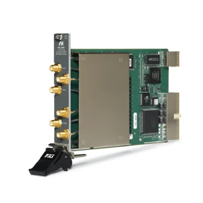


PXI-2594 2.5 GHz 4×1 RF Multiplexer
The NI PXI-2594 is a 2.5 GHz, 50 Ω, 4×1 RF multiplexer switch module for routing high-frequency signals in automated test equipment. It connects one of four SMA channel ports to a common SMA port using latching electromechanical relays.
The module provides low insertion loss, controlled impedance, good VSWR and high channel isolation. It is suitable for RF source selection, receiver input routing, antenna switching, communications testing and multi-DUT production systems.
Key Features of the PXI-2594
- 4×1 unterminated RF multiplexer topology
- DC to 2.5 GHz operating frequency
- 50 Ω nominal characteristic impedance
- Four channel ports and one common port
- Five front-panel SMA jacks
- 30 V maximum switching voltage
- 0.5 A switching and carry current
- 10 W maximum RF power
- Less than 1.35 dB insertion loss to 2.5 GHz
- Greater than 35 dB isolation to 2.5 GHz
- Latching electromechanical relays
- Onboard relay-count tracking
- PXI trigger and NI-SWITCH support
PXI-2594 Technical Specifications
| Product Model | PXI-2594 |
|---|---|
| Part Number | 778572-94 |
| Product Type | PXI RF Multiplexer Switch |
| Topology | 4×1 unterminated multiplexer |
| Frequency Range | DC to 2.5 GHz |
| Characteristic Impedance | 50 Ω nominal |
| Maximum Switching Voltage | 30 V |
| Maximum Switching Current | 0.5 A |
| Maximum Carry Current | 0.5 A |
| Maximum RF Power | 10 W |
| Insertion Loss to 1 GHz | Less than 0.60 dB |
| Insertion Loss to 2 GHz | Less than 1.10 dB |
| Insertion Loss to 2.5 GHz | Less than 1.35 dB |
| Isolation to 1 GHz | Greater than 55 dB |
| Isolation to 2 GHz | Greater than 45 dB |
| Isolation to 2.5 GHz | Greater than 35 dB |
| Typical Channel-to-Channel Skew | Less than 1 ps |
| Typical Propagation Delay | Less than 700 ps |
| Typical Rise Time | Less than 74 ps |
| Relay Operate Time | 10.4 ms |
| Listed Scan Rate | 45 cycles/s |
| Relay Type | Electromechanical, latching |
| Expected Mechanical Life | 1 × 10⁶ cycles |
| I/O Connectors | Five SMA jacks |
| Bus Connection | PXI hybrid |
| Operating Temperature | 0°C to 55°C |
| Module Format | 3U, one-slot PXI/cPCI module |
| Weight | 197 g |
4×1 RF Multiplexer Architecture
The PXI-2594 routes one of four channel inputs to a single common connection. It can be used in either direction, allowing one source to address several DUT paths or allowing several sources to share one instrument input.
Only routes permitted by the 4×1 topology should be closed. Software should disconnect the existing channel before selecting another path when the connected sources could conflict.
2.5 GHz RF Performance
The module maintains less than 1.35 dB insertion loss through 2.5 GHz. Its insertion loss is lower at lower frequencies, measuring less than 0.60 dB through 1 GHz.
Isolation is greater than 55 dB through 1 GHz, greater than 45 dB through 2 GHz and greater than 35 dB through 2.5 GHz.
Low Skew and Fast Signal Response
Typical channel-to-channel skew is less than 1 ps, typical propagation delay is below 700 ps and typical rise time is below 74 ps.
These characteristics help preserve timing relationships when routing high-speed pulses and broadband RF signals.
10 W RF Power Handling
The PXI-2594 can carry as much as 10 W of RF power while remaining within the simultaneous voltage and current limits. Higher-power sources should be disabled or reduced before switching.
During relay movement, the signal path is temporarily unterminated. Some RF generators or amplifiers can be damaged by high reflected power if their outputs are not properly protected.
Unterminated Signal Paths
Unlike the PXI-2545, the PXI-2594 does not internally terminate unused channels. External 50 Ω terminations can be installed when inactive sources or DUT paths require a defined load.
This unterminated architecture avoids the lower power limitations associated with internal terminations but requires the system designer to manage unused RF ports.
Relay-Count Tracking
Onboard relay-count tracking records switching activity. Maintenance personnel can use the count to identify heavily used channels and plan relay service before a failure interrupts production.
Electrical life depends strongly on RF power, DC voltage, current, switching frequency and whether active signals are switched.
Typical PXI-2594 Applications
- RF signal-generator routing
- Spectrum-analyzer input selection
- RF receiver testing
- Antenna-path switching
- Communications equipment validation
- RF component characterization
- Multi-DUT production testing
- Automated test equipment
- High-speed pulse routing
NI-SWITCH Software Support
NI-SWITCH provides software functions for connecting a channel to the common, disconnecting routes, configuring scan lists, selecting PXI trigger sources and reading relay counts.
NI Switch Executive can combine the PXI-2594 with other switch modules and define logical route names for use in LabVIEW or TestStand sequences.
PXI Hardware Triggering
The module accepts input triggers from PXI trigger lines 0 through 7. The minimum specified trigger pulse width is 150 ns with the standard digital-filter configuration.
Output triggers can be sent to the PXI trigger bus to coordinate route completion with RF generators, analyzers or digitizers.
PXI-2594 Troubleshooting
The module is not detected in NI MAX
Confirm that the PXI-2594 is fully installed in a compatible PXI or hybrid slot. Check chassis power, controller communication and NI-SWITCH installation.
No signal appears at the common port
Verify the selected channel and route. Inspect SMA cables and confirm that another route has not been left in an incompatible state.
Insertion loss is higher than expected
Inspect SMA connector condition, cable loss, adapter loss and the calibration reference plane. Compare measurements with the correct frequency-dependent limit.
An inactive source shows unexpected reflections
The PXI-2594 is unterminated. Install a suitable external 50 Ω termination if the source requires a defined load while disconnected.
The relay does not switch reliably
Check the relay count and test the path without active RF power. Confirm that the connected voltage, current and power have remained within specification.
PXI-2594 vs PXI-2545
| Feature | PXI-2594 | PXI-2545 |
|---|---|---|
| Topology | Unterminated 4×1 | Terminated 4×1 |
| Maximum Frequency | 2.5 GHz | 2.7 GHz |
| Insertion Loss | Less than 1.35 dB to 2.5 GHz | Less than 2 dB to 2.7 GHz |
| Internal 50 Ω Terminations | No | Yes |
| Best Suited For | Low-loss, unterminated signal routing | Applications requiring terminated inactive channels |
PXI-2594 vs PXI-2595
The PXI-2594 provides a 4×1 topology and operates to 2.5 GHz. The PXI-2595 provides higher-frequency switching up to 5 GHz but uses a different topology and performance envelope.
Choose the PXI-2594 when four-channel routing, low insertion loss and 2.5 GHz coverage meet the application requirements.
Recommended Related Products
- PXI-2545 2.7 GHz Terminated RF Multiplexer
- PXI-2595 5 GHz RF Multiplexer
- PXIe-2593 500 MHz Configurable RF Multiplexer
- PXI-2593 500 MHz Configurable RF Multiplexer
- View More NI PXI Switch Modules
Frequently Asked Questions
What is the PXI-2594 part number?
The standard NI ordering part number is 778572-94.
What is the PXI-2594 topology?
It is a four-channel-to-one-common, or 4×1, RF multiplexer.
What is the maximum frequency?
The module is specified for RF signals from DC to 2.5 GHz.
Does it include internal termination?
No. The PXI-2594 is an unterminated multiplexer.
What is the maximum RF power?
The maximum RF power is 10 W, subject to the 30 V and 0.5 A limits.
Does the PXI-2594 use latching relays?
Yes. It uses latching electromechanical relays.
Can relay usage be monitored?
Yes. The module supports onboard relay-count tracking.
Which software controls the PXI-2594?
The module is controlled with NI-SWITCH and can be integrated with NI Switch Executive.
Request a Quote for the PXI-2594
Contact us for current availability, lead time and project pricing for the PXI-2594 2.5 GHz 4×1 RF Multiplexer. We can also help select SMA cables, external terminations and related RF switch modules.















