






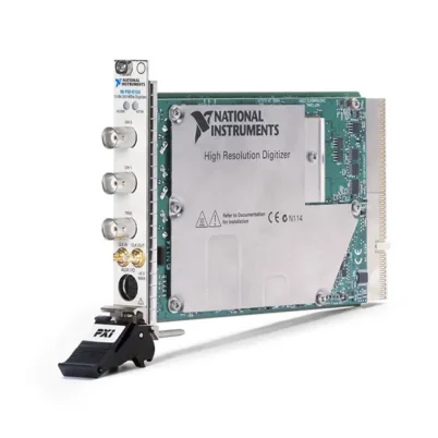
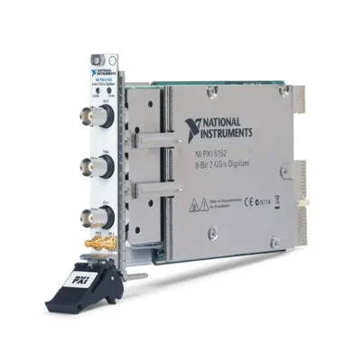
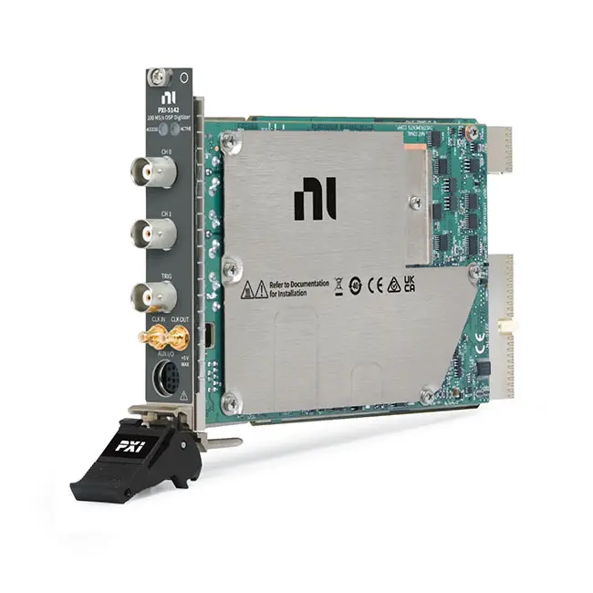
PXI-5142 14-Bit 100 MS/s Digitizer with Onboard Signal Processing
The NI PXI-5142 is a two-channel, 14-bit PXI digitizer designed for communications measurements, intermediate-frequency signal acquisition and high-resolution time-domain or frequency-domain analysis. It provides real-time sampling at up to 100 MS/s, analog bandwidth up to 100 MHz and onboard signal processing for digital downconversion, decimation and baseband I/Q filtering.
The PXI-5142 can operate as a standalone high-resolution oscilloscope or as the digitizer component of an RF signal analyzer. When combined with the PXI-5600 RF downconverter, it forms part of the PXI-5661 vector signal analyzer architecture.
Key Features of the PXI-5142
- Two simultaneously sampled analog input channels
- 14-bit vertical resolution
- 100 MS/s real-time sampling rate
- Up to 2 GS/s random-interleaved sampling for repetitive signals
- Up to 100 MHz analog bandwidth
- Onboard digital signal processing
- Onboard digital downconversion
- Real and complex I/Q acquisition modes
- Programmable decimation and baseband filtering
- Alias-protected baseband I/Q processing
- Input ranges from 200 mVpp to 20 Vpp
- 50 Ω or 1 MΩ selectable input impedance
- AC, DC and ground coupling
- Selectable analog noise and antialias filters
- 64 MB or 256 MB memory per channel
- Pretrigger and post-trigger acquisition
- Multiple-record waveform acquisition
- Advanced analog and digital triggering
- PXI reference-clock synchronization
- NI-TClk multimodule synchronization
- Built-in self-calibration
- NI-SCOPE driver support
PXI-5142 Technical Specifications
| Product Model | PXI-5142 |
|---|---|
| Product Type | PXI high-resolution digitizer with onboard signal processing |
| Analog Input Channels | 2, simultaneously sampled |
| Vertical Resolution | 14 bits |
| Maximum Real-Time Sample Rate | 100 MS/s |
| Maximum Random-Interleaved Sample Rate | 2 GS/s for repetitive signals |
| Maximum Analog Bandwidth | 100 MHz |
| Input Type | Referenced single-ended |
| Input Impedance | 50 Ω or 1 MΩ |
| Input Voltage Ranges | 200 mVpp to 20 Vpp |
| Input Coupling | AC, DC or ground, depending on impedance selection |
| Analog Filtering | Full-bandwidth, noise-filter and antialias-filter configurations |
| Onboard Processing | Digital downconversion, decimation and baseband filtering |
| Processing Output Modes | Real or complex I/Q data |
| Baseband Alias Protection | Integrated digital filtering |
| Onboard Memory Options | 64 MB or 256 MB per channel |
| Maximum Records | Up to 100,000 records, depending on memory and record length |
| Trigger Types | Edge, window, hysteresis, video, digital, immediate and software |
| Trigger Sources | Analog channels, front-panel trigger, PXI trigger lines and software |
| Internal Sample Clock | 100 MHz voltage-controlled crystal oscillator |
| Reference Clock | PXI 10 MHz reference or supported external reference clock |
| Front-Panel Analog Connectors | 2 × BNC |
| External Trigger Connector | BNC |
| Clock Connections | Front-panel clock input and output |
| Self-Calibration | Gain, offset, frequency response, trigger and timing calibration |
| External Calibration Interval | 2 years |
| Recommended Warm-Up Time | 15 minutes |
| Software Driver | NI-SCOPE |
| Bus Interface | PXI; compatible with supported PXI Express hybrid slots |
| Module Format | 3U, one-slot PXI module |
| Operating Temperature | 0°C to 45°C |
| Storage Temperature | −40°C to 71°C |
| Dimensions | Approximately 21.6 × 2.0 × 13.0 cm |
| Weight | Approximately 459 g |
PXI-5142 Part Numbers and Memory Options
| Product Configuration | Part Number | Onboard Memory |
|---|---|---|
| PXI-5142 Standard Memory | 779587-01 | 64 MB per channel |
| PXI-5142 Extended Memory | 779587-02 | 256 MB per channel |
| PXI-5600 RF Downconverter | Configuration dependent | RF downconverter used with the PXI-5142 in PXI-5661 systems |
| 50 Ω BNC Cable | Configuration dependent | Coaxial cable for high-frequency and IF signal connections |
| Clock Cable | Configuration dependent | Cable for external sample-clock or reference-clock synchronization |
The PXI-5142 is available with either 64 MB or 256 MB of memory per channel. Both versions provide the same fundamental sampling, resolution, bandwidth and onboard-processing capabilities.
Two Simultaneously Sampled Inputs
The PXI-5142 provides two independent 14-bit analog input channels that sample simultaneously. This preserves the phase relationship between signals and enables synchronized acquisition of I and Q baseband inputs.
Simultaneous sampling is also useful for comparing a stimulus and response, measuring propagation delay or analyzing two related communication signals.
14-Bit Vertical Resolution
The 14-bit ADC provides 16,384 theoretical amplitude levels across the selected range. This high resolution helps identify low-level components in both time-domain waveforms and frequency-domain spectra.
Compared with an 8-bit oscilloscope, the PXI-5142 provides 64 times more theoretical quantization levels. Actual performance also depends on noise, distortion, range and input frequency.
100 MS/s Real-Time Sampling
The module samples at rates up to 100 MS/s in conventional oscilloscope mode. Real-time acquisition captures a complete waveform from one occurrence without requiring it to repeat.
This mode is appropriate for modulated communications signals, pulses, transients and other events that may change from one acquisition to the next.
2 GS/s Random-Interleaved Sampling
For stable repetitive signals, random-interleaved sampling provides an effective sampling rate of up to 2 GS/s. Samples captured from multiple repetitions are combined to produce finer time spacing.
RIS should not be used for single-shot, burst or changing waveforms because it assumes the signal remains consistent between acquisitions.
100 MHz Analog Bandwidth
The 100 MHz analog input bandwidth supports baseband, intermediate-frequency and general-purpose electronic waveform measurements.
Undersampling can be used for certain signals with carrier frequencies above the first Nyquist region, provided the signal bandwidth, filtering and alias position are understood and controlled.
Onboard Signal Processing
The distinguishing feature of the PXI-5142 is its onboard signal-processing block. The module can digitally downconvert and filter the acquired signal before transferring data to the PXI controller.
Onboard processing reduces the amount of data that must cross the PXI bus when only a narrow portion of the input spectrum is required. This enables longer acquisitions and reduces host-processor workload.
Digital Downconversion
The digital downconverter translates a selected intermediate-frequency band to baseband. A numerically controlled oscillator provides the digital mixing frequency, while onboard filters isolate the desired bandwidth.
The output can be returned as complex I/Q samples for modulation and vector-signal analysis. This eliminates the need to transfer the complete 100 MS/s waveform when the signal of interest occupies a much narrower bandwidth.
Real and Complex I/Q Modes
In real mode, onboard processing returns a decimated real-valued waveform. In complex mode, the PXI-5142 generates in-phase and quadrature data representing both amplitude and phase.
Complex I/Q data is used to analyze digitally modulated signals, frequency translation, phase behavior and communications parameters.
Programmable Decimation
Decimation reduces the output sample rate after the signal has been digitally filtered. The process retains the selected baseband information while reducing the number of samples transferred and stored.
Lower output rates allow longer acquisition times. For example, the 256 MB version can record substantially longer waveforms in processed modes than when storing full-rate 100 MS/s data.
Alias-Protected Baseband Filtering
Digital filters provide alias protection before the processed sample rate is reduced. The passband contains the desired real or complex signal, while out-of-band frequency components are attenuated.
The requested I/Q rate and analysis bandwidth should be selected according to the occupied bandwidth and transition-band requirements of the measured signal.
64 MB and 256 MB Memory Options
The PXI-5142 offers 64 MB or 256 MB of onboard memory per channel. In full-rate mode, the larger version provides a longer uninterrupted acquisition window.
When onboard decimation is enabled, the reduced output data rate further increases the total acquisition duration available from the installed memory.
Multiple-Record Acquisition
The module supports multiple-record acquisition for capturing repeated signal events without recording long inactive intervals. Up to 100,000 records can be stored under supported memory and record-length conditions.
This mode is useful for communications bursts, radar pulses, switching events and other signals that occur intermittently.
Pretrigger and Post-Trigger Capture
Pretrigger samples record the waveform before the trigger condition. Post-trigger samples capture the event after the trigger, and the trigger position can be configured within the acquisition record.
Pretrigger acquisition is helpful for determining what caused an abnormal communications burst, transient or device failure.
Advanced Triggering
The PXI-5142 supports edge, window, hysteresis, video, digital, immediate and software triggering. Analog channels, external connectors and PXI trigger lines can be used as trigger sources.
Window triggering detects when a signal enters or leaves a voltage band. Hysteresis improves stability when noise is present near the trigger threshold.
50 Ω Input Impedance
The 50 Ω input path is optimized for RF, IF and communications signal sources. Matching the source, cable and input impedance reduces reflections and provides improved signal integrity.
Observe the voltage and power limits of the internal termination. Excessive input power can damage the digitizer.
1 MΩ Input Impedance
The 1 MΩ input path minimizes loading on high-impedance circuits and supports conventional passive probes. Input capacitance, probe capacitance and source impedance should be considered at higher frequencies.
Use short, compensated connections when measuring fast electronic waveforms through the high-impedance path.
Flexible Input Ranges
Input ranges from 200 mVpp to 20 Vpp allow the PXI-5142 to measure low-amplitude IF signals and higher-voltage electronic waveforms. Each input channel can be configured independently.
Select the smallest range that safely contains the signal, including DC offset, noise and transient peaks, to maximize use of the 14-bit ADC.
Analog Noise and Antialias Filters
Selectable analog filtering helps reduce out-of-band noise before the signal reaches the ADC. The noise filter provides more than 20 dB of attenuation at 100 MHz and is useful for lower-frequency measurements.
The antialias configuration limits unwanted frequency content that could fold into the acquisition band. For digital downconversion, additional alias protection is provided by the onboard processing filters.
PXI-5600 RF Downconverter Integration
The PXI-5142 can receive an intermediate-frequency waveform from the PXI-5600 RF downconverter. The PXI-5600 translates an RF signal to an IF suitable for digitization and onboard processing.
Together, these modules form the measurement hardware used in the PXI-5661 vector signal analyzer. The system supports RF spectrum, modulation and vector-signal analysis within the limits of the complete configuration.
Standalone Digitizer Operation
The PXI-5142 does not require an RF downconverter for ordinary waveform acquisition. It can operate as a standalone two-channel high-resolution oscilloscope for baseband, IF and electronic measurements.
Standalone operation retains access to onboard processing, triggering, deep memory, filtering and PXI synchronization.
PXI Clock and Trigger Synchronization
The internal 100 MHz oscillator can phase lock to the PXI 10 MHz backplane reference clock or a supported external reference. PXI trigger lines coordinate acquisition with other instruments.
Common timing resources are useful when the PXI-5142 operates with an RF downconverter, signal generator, digital waveform module or additional digitizer.
NI-TClk Multimodule Synchronization
NI-TClk aligns acquisition clocks and trigger events across compatible modular instruments. Multiple PXI-5142 modules can be combined for phase-coherent multichannel measurements.
The module can also synchronize with an PXI-5421 arbitrary waveform generator to create coordinated communications stimulus-and-response systems.
Built-In Self-Calibration
Self-calibration corrects gain, offset, frequency response, triggering and timing behavior according to the current operating temperature. A 15-minute warm-up period is recommended before calibration or precision measurements.
External calibration adjusts the onboard reference and timing source. NI specifies a two-year external calibration interval.
Communications Signal Measurements
The PXI-5142 is optimized for communications signals that require high-resolution sampling and efficient baseband processing. It can acquire modulated IF signals and return real or complex data for software analysis.
Supported applications include GSM, W-CDMA, DVB and QAM-related measurements when the complete hardware, software and signal configuration meet the required bandwidth and performance limits.
Vector Signal Analysis
Complex I/Q data from the onboard DDC can be processed to calculate modulation error ratio, error vector magnitude, constellation diagrams, phase error and spectral characteristics.
NI modulation-analysis software or custom LabVIEW code can analyze the acquired I/Q data according to the required communications standard.
Spectrum and Frequency-Domain Analysis
The 14-bit ADC and onboard processing allow the PXI-5142 to analyze narrowband portions of a wider input spectrum. Digital downconversion isolates the required signal and reduces the output data rate.
This approach is useful for spectral monitoring, harmonic measurement, interference analysis and IF characterization.
Radar and Pulsed-Signal Testing
Multiple-record mode can capture repeated radar, sonar or communications pulses while omitting the inactive time between events. Hardware timestamps preserve the timing relationship among records.
Deep memory and onboard processing allow long sequences of narrowband pulse data to be stored efficiently.
Automated Production Testing
The PXI-5142 integrates into automated production systems requiring waveform, spectrum or modulation measurements. Software-defined configuration allows one module to perform several types of analysis during a test sequence.
PXI synchronization coordinates the digitizer with signal generators, switches and device-control hardware to improve test repeatability and throughput.
NI-SCOPE Software Support
The PXI-5142 is controlled through the IVI-compliant NI-SCOPE instrument driver. NI-SCOPE provides functions for configuring inputs, clocks, triggers, acquisition memory and onboard processing.
The driver supports LabVIEW, LabWindows/CVI, Measurement Studio and compatible C, C++ and .NET environments. A soft front panel can be used for basic waveform acquisition and hardware troubleshooting.
Typical PXI-5142 Applications
- Intermediate-frequency signal acquisition
- Digital downconversion
- Complex I/Q waveform acquisition
- Vector signal analysis
- Modulation-quality measurements
- GSM, W-CDMA, DVB and QAM testing
- Spectrum and harmonic analysis
- RF signal-analyzer systems
- Radar and pulsed-signal acquisition
- Communications production testing
- Baseband signal measurements
- High-resolution waveform acquisition
- Aerospace and defense testing
- Scientific research
- Synchronized mixed-signal systems
PXI-5142 Troubleshooting
The PXI-5142 is not detected in NI MAX
Confirm that the module is fully installed in a compatible PXI or PXI Express hybrid peripheral slot. Check chassis power, controller communication and NI-SCOPE installation, then restart NI Measurement & Automation Explorer.
The acquired waveform is clipped
Select a larger input range or adjust the vertical offset. Confirm that the signal, DC component and transient peaks remain within the configured range.
The measured amplitude is incorrect
Check the selected 50 Ω or 1 MΩ input impedance and the source termination. Verify probe attenuation and software scaling.
The I/Q spectrum appears at the wrong frequency
Verify the digital downconverter center frequency, sample rate, decimation and external RF downconverter configuration. Confirm whether the frequency conversion uses high-side or low-side injection.
The processed waveform bandwidth is too narrow
Increase the requested I/Q rate or reduce the decimation factor. Confirm that the selected signal lies inside the digital filter passband.
Aliasing appears in the processed data
Review the analog input filter, digital downconversion frequency and baseband bandwidth. Confirm that strong out-of-band signals are sufficiently attenuated before decimation.
The acquisition duration is shorter than expected
Check whether the module is operating in real or complex mode. Complex I/Q samples require additional memory. Increase decimation or select the 256 MB version for longer captures.
The trigger is unstable
Verify the trigger source, level, slope, coupling and hysteresis. Confirm that the selected trigger signal crosses the threshold consistently.
The PXI-5600 and PXI-5142 do not operate as one analyzer
Confirm both modules are recognized, connected correctly and configured through compatible RF and NI-SCOPE software. Verify IF routing, reference-clock sharing and trigger configuration.
PXI-5142 Comparison with Similar Digitizers
| Model | Primary Configuration | Best Suited For |
|---|---|---|
| PXI-5122 | 2 channels, 14-bit, 100 MS/s, 100 MHz | High-resolution general-purpose waveform measurements |
| PXI-5124 | 2 channels, 12-bit, 200 MS/s, 150 MHz | Faster and wider-bandwidth waveform acquisition |
| PXI-5142 | 2 channels, 14-bit, 100 MS/s with onboard DDC | Communications, IF and complex I/Q measurements |
| PXIe-5122 | 2 channels, 14-bit, 100 MS/s, PXI Express | Modern high-resolution PXI Express waveform systems |
| PXIe-5622 | 16-bit, 150 MS/s communications digitizer | Higher-resolution PXI Express IF and RF signal analysis |
PXI-5142 vs PXI-5122
The PXI-5142 and PXI-5122 both provide two 14-bit channels, 100 MS/s real-time sampling and approximately 100 MHz analog bandwidth.
The PXI-5142 adds onboard digital downconversion, decimation and complex I/Q filtering. Choose the PXI-5142 for communications and narrowband IF analysis. Select the PXI-5122 for general-purpose high-resolution oscilloscope measurements.
PXI-5142 vs PXI-5124
The PXI-5124 provides 12-bit resolution, 200 MS/s sampling and 150 MHz bandwidth. The PXI-5142 provides higher 14-bit resolution and onboard signal processing but uses a lower 100 MS/s real-time sampling rate.
Choose the PXI-5142 for digital downconversion and communications measurements. Select the PXI-5124 for faster general-purpose waveform acquisition.
PXI-5142 vs PXIe-5622
The PXIe-5622 is a newer PXI Express communications digitizer with 16-bit resolution and a higher maximum sampling rate. The PXI-5142 remains useful for maintaining existing PXI-5661 systems and legacy communications test platforms.
Choose the PXI-5142 for compatibility with established PXI hardware and software. Consider the PXIe-5622 for newer systems requiring improved resolution, throughput and PXI Express connectivity.
Recommended Related Products
- PXI-5600 RF Downconverter
- PXI-5661 Vector Signal Analyzer
- PXI-5122 14-Bit 100 MS/s Digitizer
- PXI-5124 12-Bit 200 MS/s Digitizer
- PXI-5421 Arbitrary Waveform Generator
- PXIe-5622 16-Bit Communications Digitizer
- PXIe-5663 Vector Signal Analyzer
- View More NI PXI RF and Digitizer Modules
Selecting the Right Communications Digitizer
Choose the PXI-5142 when the application requires 14-bit resolution, 100 MS/s acquisition and onboard digital downconversion. It is especially useful for narrowband IF, baseband I/Q and modulation measurements.
Select the PXI-5122 when onboard DDC is unnecessary and a general-purpose high-resolution oscilloscope is preferred. Choose the PXI-5124 when higher sampling rate and bandwidth are more important than 14-bit resolution.
The 64 MB version is suitable for shorter waveform records. Select the 256 MB version for longer full-rate acquisitions, additional records or extended processed I/Q captures.
Why Choose the PXI-5142?
- Provides two simultaneously sampled 14-bit channels
- Supports real-time sampling up to 100 MS/s
- Offers analog bandwidth up to 100 MHz
- Performs digital downconversion onboard
- Generates real or complex I/Q data
- Provides programmable decimation and filtering
- Reduces PXI bus and host-processing requirements
- Supports up to 256 MB memory per channel
- Works with the PXI-5600 in PXI-5661 systems
- Supports PXI triggering and NI-TClk synchronization
- Integrates with NI-SCOPE and LabVIEW
Frequently Asked Questions
What is the PXI-5142?
The PXI-5142 is a two-channel, 14-bit PXI digitizer with 100 MS/s sampling, 100 MHz bandwidth and onboard digital downconversion and filtering.
What are the PXI-5142 part numbers?
Part number 779587-01 provides 64 MB per channel, while part number 779587-02 provides 256 MB per channel.
What is the maximum real-time sample rate?
The maximum real-time sampling rate is 100 MS/s.
What is the analog bandwidth?
The PXI-5142 provides analog input bandwidth up to 100 MHz.
What is the vertical resolution?
The module uses 14-bit analog-to-digital converters, providing 16,384 theoretical amplitude levels.
Does the PXI-5142 include digital downconversion?
Yes. The onboard signal-processing block performs digital frequency translation, decimation and baseband filtering.
Can the PXI-5142 acquire complex I/Q data?
Yes. It can return complex in-phase and quadrature samples for modulation and vector-signal analysis.
Can the PXI-5142 be used as a standalone oscilloscope?
Yes. It can operate as a standalone two-channel digitizer without the PXI-5600 RF downconverter.
How is the PXI-5142 used in a PXI-5661?
The PXI-5600 converts the RF signal to an intermediate frequency, and the PXI-5142 digitizes and processes that IF waveform.
Does the module support 50 Ω and 1 MΩ inputs?
Yes. The analog input channels support software-selectable 50 Ω and 1 MΩ input impedance.
Can multiple PXI-5142 modules be synchronized?
Yes. Multiple compatible modules can share PXI clocks and triggers through NI-TClk synchronization.
Which driver controls the PXI-5142?
The PXI-5142 is controlled through the NI-SCOPE instrument driver.
Can the PXI-5142 operate in a PXI Express chassis?
Yes. It can operate in a compatible PXI Express hybrid peripheral slot, but not in a PXI Express-only slot without the hybrid connector.
Request a Quote for the PXI-5142
Contact us for current availability, memory configuration, product condition, calibration status, lead time and project pricing for the PXI-5142 14-Bit 100 MS/s Digitizer with Onboard Signal Processing. We can also help identify compatible PXI-5600 downconverters, cables, PXI chassis, signal generators and RF measurement software.















