







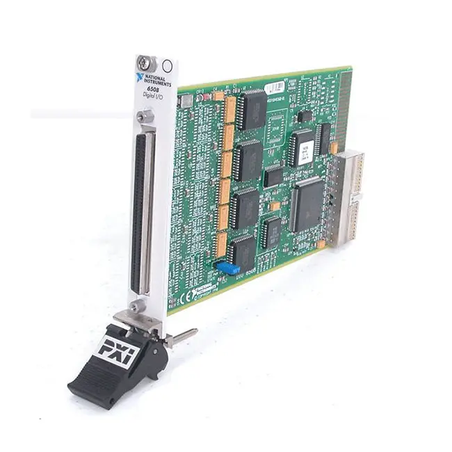
PXI-6508 96-Channel 5 V TTL/CMOS Digital I/O Module
The PXI-6508 is a 96-channel parallel digital I/O module designed for PXI and CompactPCI automated test systems. It provides software-configurable 5 V TTL/CMOS digital lines for monitoring logic states, controlling test fixtures and communicating with parallel digital devices.
The module uses four programmable peripheral interface controllers. Each controller provides 24 digital lines organized as three 8-bit ports, creating a total of 96 digital I/O channels.
In addition to basic static input and output, the PXI-6508 supports strobed input, strobed output, bidirectional bus communication, handshaking and interrupt generation. This makes it suitable for both general-purpose digital control and legacy parallel peripheral interfaces.
Key Features of the PXI-6508
- 96 programmable digital I/O lines
- 5 V TTL/CMOS signal compatibility
- Four 24-bit programmable peripheral interfaces
- Twelve 8-bit digital ports
- Software-configurable input and output direction
- Mode 0 basic digital I/O
- Mode 1 strobed input and output
- Mode 2 bidirectional bus operation
- Two-wire handshaking support
- Interrupt generation and status monitoring
- Latched digital outputs
- Up to 50 kbytes/s handshaked transfer rate
- Two usable onboard timer channels
- 100-pin female D-Type front connector
- Compatible with the R1005050 breakout cable
- NI-DAQmx software support
- Single-slot 3U PXI module
PXI-6508 Technical Specifications
| Product Model | PXI-6508 |
|---|---|
| Part Number | 777598-01 |
| Product Type | PXI parallel digital I/O module |
| Number of Digital I/O Lines | 96 |
| Digital Signal Standard | 5 V TTL/CMOS compatible |
| Programmable Interfaces | 4 × 82C55A-compatible 24-bit PPIs |
| Port Organization | 12 × 8-bit ports |
| Direction Control | Software configurable by port or port section |
| Mode 0 | Basic input and output |
| Mode 1 | Strobed input or strobed output with handshaking |
| Mode 2 | Bidirectional 8-bit bus with handshaking |
| Maximum Handshaked Transfer Rate | Up to 50 kbytes/s |
| Data Transfer | Programmed I/O and interrupts |
| Output Drive | Approximately 2.5 mA per line, subject to logic level |
| Absolute Digital Signal Range | Approximately -0.5 V to +5.5 V relative to digital ground |
| Onboard Timer | 82C53-compatible interval timer |
| Usable Timer Channels | 2 internally configured channels |
| Timer Source Clock | 2 MHz for Counter 0 |
| Front-Panel Connector | 100-pin female D-Type connector |
| Bus Interface | PXI and CompactPCI compatible |
| Module Format | 3U, single-slot PXI module |
| Power Consumption | Approximately 400 mA from +5 VDC |
| Operating Temperature | 0°C to 55°C |
| Storage Temperature | -20°C to 70°C |
| Weight | Approximately 148 g |
| Software Support | NI-DAQmx and applicable legacy NI-DAQ software |
| Availability Status | Discontinued by NI |
PXI-6508 Part Number and Accessories
| Item | Part Number | Description |
|---|---|---|
| PXI-6508 | 777598-01 | 96-channel, 5 V TTL/CMOS PXI parallel digital I/O module |
| R1005050 Cable | Application dependent | Converts the 100-pin module connector into two 50-pin accessory connections |
| CB-50LP | 777101-01 | 50-pin low-profile screw-terminal connector block |
| SCB-100 | Application dependent | Shielded high-density terminal accessory for custom digital wiring |
| 100-Pin Custom Connector | Application dependent | Mating connector for custom test-fixture cable construction |
| PXI-6509 | Verify configuration | Newer 96-channel static digital I/O alternative with higher output drive |
The R1005050 cable divides the PXI-6508’s 100-pin connection into two 50-pin connectors. One connector carries module pins 1 through 50, while the other carries pins 51 through 100.
The R1005050 and older NB5 cables have different pin assignments and are not interchangeable. Verify the cable label and pinout before connecting a terminal block or existing fixture.
96 Programmable Digital I/O Lines
The PXI-6508 provides 96 logic-level digital lines for high-channel-count test and control applications. The lines can monitor switches and logic states or control multiplexers, fixture relays through external drivers and other digital circuitry.
The module is intended for 5 V TTL/CMOS-compatible equipment. It should not be connected directly to 24 V industrial devices, mains circuits or high-current loads.
External isolation, level conversion or driver circuitry is required when the device under test uses voltage or current levels beyond the PXI-6508 ratings.
Four Programmable Peripheral Interfaces
The 96 digital lines are provided by four programmable peripheral interface controllers identified as PPI A, PPI B, PPI C and PPI D.
Each PPI has 24 lines divided into Port A, Port B and Port C. Ports A and B contain eight lines each. Port C contains eight lines that can also be divided into upper and lower 4-bit sections for direction control or handshaking.
Every PPI can be configured independently, allowing different portions of the module to perform basic I/O, strobed transfers or bidirectional communication.
Twelve 8-Bit Digital Ports
The PXI-6508 presents its channels as twelve 8-bit ports. Port-based organization is useful when the connected device exchanges bytes or when a fixture groups related control signals together.
In basic I/O mode, Ports A and B can be configured independently as input or output. The upper and lower halves of Port C can also be assigned separate directions.
Direction changes should be performed carefully because every line in the affected port or port section changes function together.
Mode 0 Basic Digital I/O
Mode 0 provides general-purpose static input and output without handshaking. Software reads input ports or writes output ports whenever required by the application.
Outputs are latched and retain the programmed logic state until changed by software, reset or power cycling. Inputs represent the logic level present when the port is read.
Mode 0 is suitable for switches, fixture-state selection, status monitoring, LED control and other applications that do not require hardware-controlled transfer timing.
Mode 1 Strobed Input
Mode 1 input transfers data using hardware handshaking. An external device asserts a strobe signal when a new data byte is available, and the PPI captures the input into a latch.
Status signals indicate that the input buffer contains unread data. The module can also generate an interrupt so software does not need to continuously poll the port.
Several Port C lines become handshaking and status signals in this mode, reducing the number available as general-purpose I/O.
Mode 1 Strobed Output
Mode 1 output uses handshaking to coordinate delivery of an output byte to an external device. The PPI indicates when output data is available, and the peripheral acknowledges the transfer.
This prevents software from overwriting data before the external device has accepted the previous byte. Interrupts can notify the application when the port is ready for another transfer.
Mode 2 Bidirectional Bus
Mode 2 configures Port A as an 8-bit bidirectional bus. The same data lines carry information in both directions, while five Port C lines provide strobe, acknowledge, buffer-status and interrupt functions.
This mode is useful for communicating with legacy parallel peripherals and custom digital devices that use a shared bidirectional byte-wide interface.
Mode 2 is available only for Group A of each programmable peripheral interface. Other ports can continue operating in compatible basic or handshaked modes.
Two-Wire Handshaking
Handshaking allows the PXI-6508 and an external device to coordinate transfers even when they operate at different speeds. A request or strobe indicates that data is ready, while an acknowledgment confirms acceptance.
The exact signal allocation depends on whether a port is configured for strobed input, strobed output or bidirectional operation. Follow the official mode-specific pinout when building a cable or fixture.
Interrupt Support
The PXI-6508 can generate interrupts from compatible handshaking events. Interrupt-driven operation allows the processor to perform other tasks while waiting for an external peripheral.
When an input byte arrives or an output transfer completes, an interrupt can notify the application. This is more efficient than repeatedly polling the status lines at a high rate.
The driver and application must enable the correct interrupt source and clear or service the associated status condition.
Known Power-Up States
Digital ports initialize as inputs when the hardware is powered or reset. The input configuration presents a high-impedance state to connected logic and helps avoid actively driving an unknown output value during startup.
External circuitry should still be designed with defined pull-up or pull-down resistors when a particular safe logic level is required before software configures the module.
Test fixtures controlling safety-related loads should include independent hardware interlocks rather than relying exclusively on software-configured digital states.
5 V TTL/CMOS Compatibility
The PXI-6508 is designed for conventional 5 V logic. Input and output signals are referenced to the module’s digital ground.
Do not assume compatibility with modern low-voltage logic such as 1.8 V or 2.5 V devices. Compare input thresholds, output-high voltage and current requirements before connecting a lower-voltage device.
A bidirectional level translator may be required when the external circuit uses a different logic supply.
Digital Output Drive Capability
The digital outputs are suitable for driving compatible logic inputs but are not intended to supply substantial load current. Output voltage depends on the amount of sourced or sunk current.
Use an external buffer, transistor array or relay-driver circuit for lamps, relays, motors and solenoids. Include appropriate transient suppression when driving inductive loads.
Exceeding the per-line or combined current limits can produce incorrect logic levels or damage the module.
Onboard Interval Timer
The PXI-6508 includes an 82C53-compatible interval timer containing three counter sections. Two counter channels are internally configured for useful timing and interrupt functions, while the third is not connected for external use.
Counter 0 receives a 2 MHz clock and can be configured as a rate generator for periodic interrupts. Counter 1 can be cascaded with Counter 0 to produce longer intervals.
These timers are intended primarily for board-level timing functions and should not be confused with fully featured external event counters found on dedicated NI counter/timer modules.
Programmed I/O Transfers
The PXI-6508 uses programmed I/O for digital data movement. Software reads or writes the appropriate port through the driver rather than streaming hardware-timed waveforms with DMA.
The module supports handshaked transfers up to approximately 50 kbytes/s under suitable conditions. Actual throughput depends on mode, software overhead, operating system and external peripheral timing.
For high-speed synchronous digital waveform acquisition or generation, a dedicated high-speed digital I/O module is more appropriate.
NI-DAQmx Software Support
The PXI-6508 is supported by applicable versions of the NI-DAQmx driver. NI-DAQmx provides device identification, digital channel configuration and read/write operations.
The module can be programmed using LabVIEW, LabWindows/CVI and compatible text-based environments. NI Measurement & Automation Explorer can identify the device and provide basic digital test functions.
Because the PXI-6508 is a discontinued legacy module, verify compatibility between the module, operating system, PXI controller and NI-DAQmx version before deployment.
Typical PXI-6508 Applications
- Automated test-fixture control
- High-channel-count logic monitoring
- Parallel peripheral communication
- Switch and status input monitoring
- Multiplexer and decoder control
- Production functional testing
- Relay control through external drivers
- Legacy equipment integration
- Strobed digital data transfer
- Bidirectional parallel-bus communication
- Laboratory automation
- Educational digital-system experiments
Automated Test-Fixture Control
The 96 digital lines allow one module to control a large number of fixture functions. Applications can include selecting multiplexers, enabling power paths, operating external relay drivers and monitoring interlock signals.
Organizing related signals into 8-bit ports simplifies software and fixture documentation. Port states should be verified before enabling power to the device under test.
Parallel Peripheral Communication
The PXI-6508 can communicate with custom electronics and legacy peripherals using basic, strobed or bidirectional parallel interfaces.
Handshake modes allow reliable transfers without requiring both devices to execute at exactly the same speed. The external device must follow the signal timing and polarity defined by the selected PPI mode.
Production Functional Testing
In a production system, digital inputs can verify switch positions, connector states and device outputs. Digital outputs can select fixture modes or apply logic stimuli through suitable buffering.
The large channel count reduces the number of modules required for fixtures containing many low-speed logic signals.
PXI-6508 Troubleshooting
The module is not detected in NI MAX
Confirm that the PXI-6508 is fully installed in a compatible PXI or CompactPCI slot. Check chassis power, controller communication and installation of a driver version that supports the module.
A digital port cannot be configured line by line
The PXI-6508 uses 82C55A-style port organization. Direction is configured for an entire 8-bit port or for the upper and lower portions of Port C, rather than independently for every line.
An output remains at the wrong logic level
Confirm that the correct PPI, port and bit are being written. Check whether the port is configured as an output and verify that the connected load does not exceed the output-current capability.
Input signals always read high
Inspect the external wiring and check whether internal or external pull-up behavior is holding the inputs high. Confirm that the external device can pull the signal below the guaranteed low-level threshold.
The R1005050 pinout does not match the fixture
Verify that an R1005050 cable is being used rather than an older NB5 cable. The cables have different connector assignments and are not interchangeable.
Handshaked transfers do not complete
Check the selected PPI mode, data-port direction and Port C handshake connections. Verify strobe and acknowledgment polarity and confirm that the external device meets the required timing.
The interrupt occurs repeatedly
Read the applicable port or status register and service the handshaking condition. Verify that the application clears the event that caused the interrupt before returning from the handler.
A relay or solenoid does not operate
The PXI-6508 cannot drive high-current loads directly. Use an external driver with a suitable supply and transient suppression for inductive loads.
A 24 V signal damaged or disrupts the input
The module is designed for 5 V TTL/CMOS signals. Use an isolated 24 V digital input module or an appropriate voltage-level interface for industrial field signals.
PXI-6508 Comparison with Similar Digital I/O Modules
| Model | Primary Configuration | Best Suited For |
|---|---|---|
| PXI-6508 | 96 lines, 5 V TTL/CMOS, PPI handshaking | Legacy static and handshaked parallel digital I/O |
| PXI-6509 | 96 static lines, 5 V TTL/CMOS, higher drive | High-density static fixture control |
| PXI-6511 | 64 isolated industrial digital inputs | Monitoring higher-voltage industrial signals |
| PXI-6512 | 64 isolated sourcing digital outputs | Industrial load and PLC control |
| PXI-6528 | 24 isolated inputs and 24 relay outputs | Channel-isolated industrial switching |
PXI-6508 vs PXI-6509
Both modules provide 96 digital I/O lines for 5 V TTL/CMOS signals. The PXI-6508 uses programmable peripheral interfaces that support strobed and bidirectional handshaking modes.
The PXI-6509 is designed primarily for high-density static digital I/O and provides greater current drive. It is a suitable alternative for fixture control but is not necessarily a direct replacement for applications that use the PXI-6508’s PPI handshaking modes.
PXI-6508 vs PXI-6511
The PXI-6508 provides nonisolated 5 V logic-level input and output. The PXI-6511 provides isolated industrial digital inputs for higher-voltage field signals.
Select the PXI-6508 for communication with TTL/CMOS electronics. Choose the PXI-6511 for monitoring industrial sensors and controls that require isolation.
PXI-6508 vs PXI-6528
The PXI-6508 emphasizes channel density and parallel logic communication. The PXI-6528 provides fewer channels but offers channel-to-channel isolation and relay outputs.
Select the PXI-6508 for 5 V digital test fixtures. Choose the PXI-6528 when isolation and dry-contact switching are more important than channel count.
Recommended Related Products
- PXI-6509 96-Channel Digital I/O Module
- PXI-6511 Industrial Digital Input Module
- PXI-6512 Industrial Sourcing Digital Output Module
- PXI-6513 Industrial Sinking Digital Output Module
- PXI-6528 Isolated Digital I/O Module
- View More NI PXI and PXI Express Modules
Selecting the Right Digital I/O Module
Choose the PXI-6508 when an existing PXI system requires 96 TTL/CMOS digital lines and uses basic, strobed or bidirectional PPI communication modes.
Select the PXI-6509 for newer high-density static digital I/O applications. Choose an NI 651x or 652x module when industrial voltage compatibility, isolation or higher-current load control is required.
Why Choose the PXI-6508?
- Provides 96 digital I/O lines in one PXI slot
- Supports standard 5 V TTL/CMOS devices
- Organizes signals into convenient 8-bit ports
- Provides basic static input and output
- Supports strobed input and output modes
- Supports bidirectional parallel buses
- Includes handshaking and interrupt functions
- Maintains compatibility with legacy PXI fixtures
- Uses NI-DAQmx for software control
Frequently Asked Questions
What is the PXI-6508?
The PXI-6508 is a 96-channel PXI parallel digital I/O module for static, strobed and bidirectional communication with 5 V TTL/CMOS devices.
What is the PXI-6508 part number?
The standard NI part number for the PXI-6508 is 777598-01.
How many digital lines does it provide?
The module provides 96 programmable digital I/O lines organized into twelve 8-bit ports.
Can each line be configured independently?
No. Direction is configured by 8-bit port for Ports A and B or by the upper and lower 4-bit sections of Port C.
Does the PXI-6508 support handshaking?
Yes. Mode 1 supports strobed input or output, while Mode 2 supports an 8-bit bidirectional bus with hardware handshaking.
Can it connect directly to 24 V industrial signals?
No. The PXI-6508 is designed for 5 V TTL/CMOS signals. External isolation or level conversion is required for 24 V equipment.
Can it drive relays directly?
Only very-low-current logic loads should be connected directly. Most relays require an external driver and appropriate transient suppression.
Which connector does the module use?
The PXI-6508 uses a 100-pin female D-Type front-panel connector.
Which breakout cable is compatible?
The R1005050 cable converts the 100-pin module connector into two 50-pin accessory connectors. It should not be confused with the differently wired NB5 cable.
Which software controls the PXI-6508?
The module is supported by applicable NI-DAQmx versions and can be programmed using LabVIEW, LabWindows/CVI and compatible text-based environments.
Is the PXI-6508 still manufactured?
No. The PXI-6508 is a discontinued legacy module. Used and surplus units may remain available for maintaining existing PXI systems.
Request a Quote for the PXI-6508
Contact us for current availability, condition, lead time and project pricing for the PXI-6508 96-Channel 5 V TTL/CMOS Digital I/O Module. We can also help identify compatible R1005050 cables, 50-pin terminal blocks and alternative NI digital I/O modules.















