





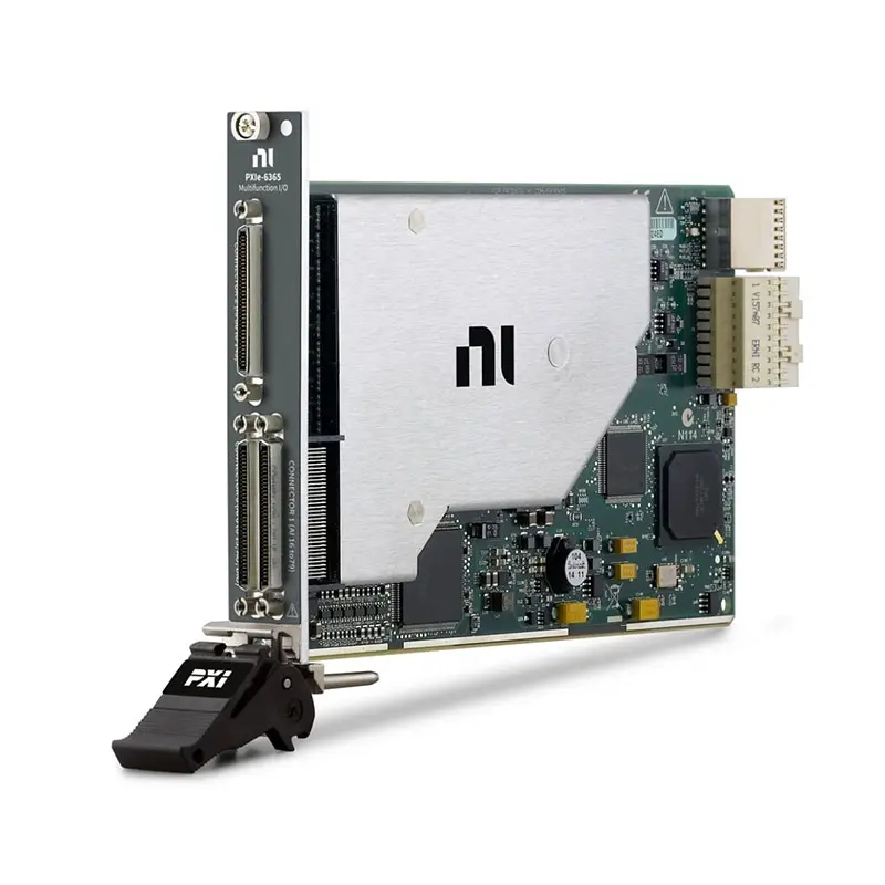
PXIe-6365 144-Channel 2 MS/s Multifunction I/O Module
Земля NI PXIe-6365 is a high-channel-count X Series PXI Express multifunction I/O module designed for automated data acquisition, electronic testing, process monitoring and control applications. It combines analog input, analog output, bidirectional digital I/O and counter/timer functions in one compact 3U PXI Express module.
The PXIe-6365 provides as many as 144 single-ended or 72 differential analog input channels with 16-bit resolution. It supports a maximum sampling rate of 2 MS/s when acquiring from one channel and an aggregate maximum rate of 1 MS/s during multichannel acquisition.
The module also includes two 16-bit analog outputs, 24 individually programmable digital I/O lines and four 32-bit counter/timers. NI-STC3 timing and synchronization technology provides independent timing engines, advanced triggering, retriggerable acquisition and flexible signal routing for complex automated test systems.
Key Features of the PXIe-6365
- 144 single-ended or 72 differential analog inputs
- 16-bit analog input resolution
- 2 MS/s maximum single-channel sampling rate
- 1 MS/s maximum aggregate multichannel sampling rate
- Seven programmable bipolar analog input ranges
- ±10 V maximum analog input range
- Two 16-bit analog output channels
- 2.86 MS/s maximum single-channel analog output rate
- 2 MS/s maximum two-channel analog output rate
- 24 individually programmable digital I/O lines
- Up to 10 MHz hardware-timed digital I/O on Port 0
- Four 32-bit general-purpose counter/timers
- Analog edge, hysteresis and window triggering
- NI-STC3 timing and synchronization technology
- PXI Express clock and trigger routing
- Three 68-pin VHDCI front-panel connectors
- NI-DAQmx and LabVIEW compatibility
PXIe-6365 Technical Specifications
| Product Model | PXIe-6365 |
|---|---|
| Part Number | 783633-01 |
| Product Family | NI X Series multifunction data acquisition |
| Шинный интерфейс | PXI Express |
| Single-Ended Analog Inputs | 144 |
| Differential Analog Inputs | 72 |
| ADC Resolution | 16 bits |
| Sampling Architecture | Multiplexed; not simultaneous sampling |
| Maximum Single-Channel Sample Rate | 2 MS/s |
| Maximum Multichannel Sample Rate | 1 MS/s aggregate |
| Minimum Sample Rate | No minimum |
| Analog Input Timing Resolution | 10 ns |
| Analog Input Timing Accuracy | 50 ppm of sample rate |
| Input Coupling | DC |
| Analog Input Ranges | ±0.1 V, ±0.2 V, ±0.5 V, ±1 V, ±2 V, ±5 V and ±10 V |
| Maximum Analog Input Working Voltage | ±11 V relative to AI GND, including signal and common mode |
| Input Impedance | Greater than 10 GΩ in parallel with 100 pF when powered |
| Common-Mode Rejection Ratio | 100 dB from DC to 60 Hz |
| Small-Signal Input Bandwidth | 1.85 MHz typical, -3 dB |
| Adjacent-Channel Crosstalk | -75 dB typical at 100 kHz |
| Non-Adjacent-Channel Crosstalk | -88 dB typical at 100 kHz |
| Analog Input FIFO | 4,095 samples |
| Scan List Memory | 4,095 entries |
| Analog Triggers | 1 |
| Analog Trigger Modes | Edge, edge with hysteresis and window triggering |
| Analog Output Channels | 2 |
| DAC Resolution | 16 bits |
| Maximum AO Update Rate | 2.86 MS/s for one channel; 2 MS/s for two channels |
| Analog Output Ranges | ±10 V, ±5 V or ±external reference through APFI 0 |
| Analog Output Current Drive | ±5 mA |
| Analog Output Settling Time | 2 µs to 15 ppm for a full-scale step |
| Analog Output Slew Rate | 20 V/µs |
| Analog Output FIFO | 8,191 samples shared between active channels |
| Digital I/O Channels | 24 bidirectional channels |
| Digital Direction Control | Each terminal individually programmable |
| Hardware-Timed Digital Lines | 8 lines on Port 0 |
| Maximum Digital Sample Clock | 10 MHz |
| Digital Input FIFO | 255 samples |
| Digital Output FIFO | 2,047 samples |
| Counter/Timers | 4 |
| Counter Resolution | 32 bits |
| Internal Counter Timebases | 100 MHz, 20 MHz and 100 kHz |
| External Counter Base Clock | Up to 25 MHz through PFI or 100 MHz through PXIe_DSTAR |
| Counter FIFO | 127 samples per counter |
| Phase-Locked Loops | 1 |
| I/O Connectors | 3 × 68-pin VHDCI |
| Operating Temperature | 0°C to 55°C |
| Module Format | Standard 3U PXI Express module |
| Weight | 203 g |
| Recommended Warm-Up Time | 15 minutes |
| External Calibration Interval | 2 years |
| Software Driver | НИ-DAQmx |
The PXIe-6365 uses multiplexed analog input architecture. The 2 MS/s specification applies when acquiring from one analog input channel, while multichannel acquisition supports an aggregate maximum rate of 1 MS/s. It does not sample all 144 channels simultaneously.
PXIe-6365 Part Number and Accessories
| Item | Part Number | Описание |
|---|---|---|
| PXIe-6365 | 783633-01 | 144-channel, 16-bit, 2 MS/s PXI Express multifunction I/O module |
| SHC68-68 Cable | 191945-02 | 2 m, 68-pin VHDCI twisted-pair cable with basic shielding |
| SHC68-68-EPM Cable | 192061-02 | 2 m shielded 68-pin D-Type to offset 68-pin VHDCI cable |
| BNC-2110 | 777643-01 | Noise-rejecting shielded BNC connector block |
| BNC-2120 | 777960-01 | Shielded BNC connector block with function-generator connections |
| SCB-68A | 782536-01 | Shielded, noise-rejecting 68-pin screw-terminal connector block |
| CB-68LPR | 777145-02 | 68-pin low-profile I/O connector block |
| CB-68LP | 777145-01 | Low-cost unshielded 68-pin I/O connector block |
The PXIe-6365 has three 68-pin VHDCI front-panel connectors. Connector 0 carries analog input, analog output, digital I/O, counter and timing signals, while the additional connectors provide access to the module’s extended analog input channels.
Accessory selection depends on the required signal groups and wiring method. Confirm the connector assignment, cable orientation, shielding, terminal-block pinout and number of required accessories before ordering.
144-Channel Analog Input Architecture
The PXIe-6365 provides 144 single-ended analog inputs or 72 differential input pairs. Single-ended operation maximizes channel density, while differential measurements can improve rejection of common-mode interference in electrically noisy systems.
The high channel count is useful when one PXI Express module must monitor many voltage signals, sensors or electronic test points. It can reduce the number of modules and chassis slots required in large automated test systems.
16-Bit Analog Input Resolution
The 16-bit ADC converts the selected analog input range into 65,536 discrete codes. Selecting the smallest suitable input range can improve the effective voltage resolution available for a particular signal.
Available bipolar ranges extend from ±100 mV to ±10 V. The correct range should provide adequate headroom for signal variation, noise and expected transients without unnecessarily reducing measurement resolution.
2 MS/s Single-Channel Sampling
The PXIe-6365 supports sampling at up to 2 MS/s when one analog input channel is active. This is useful for capturing faster voltage changes, transient events and dynamic responses that cannot be adequately characterized with lower-speed data acquisition hardware.
When multiple channels are included in a scan, the maximum aggregate sampling rate is 1 MS/s. Divide the aggregate rate by the number of scanned channels when estimating the average sampling rate available to each channel.
Multiplexed Multichannel Acquisition
A multiplexed DAQ module uses one ADC and switches its input between selected channels. The channels are sampled sequentially rather than at exactly the same instant.
This architecture provides excellent channel density and cost efficiency, but applications requiring phase-matched simultaneous sampling should use a simultaneous-sampling digitizer or dedicated dynamic signal acquisition module.
Programmable Analog Input Ranges
The module supports ±0.1 V, ±0.2 V, ±0.5 V, ±1 V, ±2 V, ±5 V and ±10 V input ranges. Different channels can be included in a scan list with the range and terminal configuration required by the application.
The maximum working voltage, including the signal and common-mode component, is ±11 V relative to analog input ground. Input signals must remain within both the selected measurement range and the applicable working-voltage limits.
Analog Input Signal Integrity
The PXIe-6365 provides 100 dB typical common-mode rejection from DC to 60 Hz and greater than 10 GΩ input impedance when powered. Its small-signal input bandwidth is approximately 1.85 MHz.
Accurate multichannel measurements also depend on signal-source impedance and settling time. Low-level ranges require more settling time following large channel-to-channel voltage steps, particularly when connected sources have high output impedance.
Analog Input Overvoltage Protection
The analog input and sense channels provide protection against voltages up to ±25 V on as many as two input pins while the module is powered. The corresponding powered-off protection level is ±15 V for as many as two pins.
These values describe protection against accidental overvoltage and do not extend the normal measurement range. Continuous operation outside the specified working-voltage limits can damage the module or connected accessories.
Flexible Analog Triggering
One onboard analog trigger can use any analog input channel or the APFI 0 terminal as its source. Supported modes include analog edge triggering, analog edge triggering with hysteresis and analog window triggering.
The analog trigger can control acquisition start, reference, pause, sample-clock and convert-clock functions. This makes it possible to capture data around a voltage threshold or only while a signal remains inside or outside a programmed window.
Two 16-Bit Analog Outputs
The PXIe-6365 includes two voltage output channels with 16-bit resolution. One channel can update at up to 2.86 MS/s, while both channels can operate at a maximum aggregate update rate of 2 MS/s.
Supported output ranges include ±10 V, ±5 V and a range defined by an external reference applied through APFI 0. Each output provides ±5 mA of current drive and a typical output impedance of 0.2 Ω.
Analog Waveform Generation
The analog outputs support non-periodic waveform generation, periodic regeneration from the onboard FIFO and regeneration from a host buffer with dynamic waveform updates.
These modes support test stimulus generation, actuator-command simulation, voltage sweeps and closed-loop control. The outputs have a 2 µs full-scale settling time to 15 ppm and a 20 V/µs slew rate.
24 Bidirectional Digital I/O Lines
The module provides 24 digital terminals divided among Port 0 and the PFI/Port 1/Port 2 connections. Each terminal can be individually programmed as a digital input or output.
All 24 lines support static operation. The eight Port 0 lines also support correlated digital waveform acquisition and generation at clock rates up to 10 MHz, subject to PXI Express bus and system activity.
Digital Filtering and Debouncing
Port 0 digital inputs support selectable filter intervals of 160 ns, 10.24 µs and 5.12 ms. PFI inputs provide configurable debounce options, including 90 ns, 5.12 µs, 2.56 ms and a programmable custom interval.
Digital filtering can suppress contact bounce, interference and narrow unwanted pulses. Filter settings should remain short enough to preserve legitimate events at the maximum expected input frequency.
Four 32-Bit Counter/Timers
Four 32-bit counter/timers support edge counting, frequency, period, semi-period, pulse-width and two-edge separation measurements. Each counter includes a dedicated 127-sample FIFO and scatter-gather DMA controller.
Position-measurement functions include X1, X2 and X4 quadrature encoder decoding with Channel Z reloading, as well as two-pulse encoding. Output functions include single pulses, dynamically updated pulse trains and frequency division.
NI-STC3 Timing and Synchronization
NI-STC3 technology provides independent analog input, analog output, digital I/O and counter timing engines. This architecture allows multiple subsystem tasks to execute with different clocks, triggers and rates.
The timing system supports retriggerable acquisition and generation, advanced trigger routing and synchronization with other PXI or PXI Express instruments. A 100 MHz timebase provides 10 ns timing resolution.
PXI Express Trigger Routing
The PXIe-6365 can use PFI terminals, PXI trigger lines, PXI_STAR and PXIe_DSTAR resources for counter, clock and trigger routing. Its phase-locked loop can lock the internal timing system to compatible 10 MHz, 20 MHz or 100 MHz reference signals.
Backplane synchronization reduces external wiring and allows measurements to be coordinated with digitizers, waveform generators, switches and other instruments installed in the same PXI Express chassis.
NI-DAQmx Software Support
The module is controlled through the NI-DAQmx driver. NI-DAQmx provides channel configuration, calibration, timing, triggering, signal routing, buffered acquisition and waveform-generation functions.
Engineers can use LabVIEW, LabWindows/CVI and supported text-based programming environments to create automated measurement applications. NI Measurement & Automation Explorer provides device detection, self-test, self-calibration and interactive test panels.
PXIe-6365 Applications
- High-channel-count voltage acquisition
- Automated electronic testing
- Production functional testing
- Design verification and validation
- Data logging and process monitoring
- Electromechanical system testing
- Motor and encoder measurements
- Hardware-in-the-loop test support
- Digital event and pulse monitoring
- Waveform generation and stimulus control
- Laboratory automation
- Research and educational systems
High-Channel-Count Data Logging
With as many as 144 single-ended inputs, the PXIe-6365 can monitor large groups of voltage signals from electronic assemblies, fixtures and industrial equipment. Multiple input ranges allow both low-level and standard ±10 V signals to be included in one test system.
Automated Electronic Testing
The module can acquire DUT voltages, generate analog stimulus, read digital status lines and produce counter-based timing signals. Integrating these functions in one device simplifies many automated functional and validation tests.
Production Functional Testing
High channel density makes the PXIe-6365 useful for fixtures that must measure many test points. Hardware timing and PXI Express data transfer help automate repeatable test sequences and reduce manual measurement steps.
Encoder and Motion Measurements
The four counters can interface with quadrature encoders, tachometers and pulse-output sensors. Applications can measure position, speed, frequency, pulse width and event count while analog channels monitor related voltages or sensor outputs.
Stimulus and Response Testing
The two analog outputs can provide programmable voltage stimulus while the analog inputs capture the DUT response. Digital lines and counter outputs can control relays, provide timing pulses or monitor state changes during the same test sequence.
Research and Laboratory Automation
The combination of analog, digital and counter functions supports automated experimental setups, educational laboratories and research instrumentation. PXI triggering allows the module to coordinate with other modular instruments in more complex systems.
PXIe-6365 Installation Workflow
Step 1: Verify Chassis Compatibility
Confirm that the chassis provides a compatible PXI Express or hybrid-compatible peripheral slot, sufficient cooling and the required backplane timing resources.
Step 2: Install NI-DAQmx
Install a version of NI-DAQmx that supports the PXIe-6365 and the operating system. Installing the driver before inserting the hardware can simplify device discovery.
Step 3: Power Down the PXI Express Chassis
Turn off and disconnect chassis power according to the chassis installation procedure. Observe appropriate electrostatic-discharge precautions when handling the module.
Step 4: Install the PXIe-6365
Insert the module into the selected compatible slot and tighten the front-panel retaining screws. Ensure that the module is completely seated in the backplane connector.
Step 5: Select the Cable and Terminal Block
Choose shielded SHC68-series cables and suitable SCB or BNC accessories according to the required signals. Consult the connector pinout before wiring any sensor, output or digital circuit.
Step 6: Connect Signals
Wire analog inputs using the appropriate differential or referenced single-ended configuration. Keep analog wiring away from digital switching lines, power conductors and other interference sources.
Step 7: Detect the Module in NI MAX
Power on the chassis and open NI Measurement & Automation Explorer. Confirm that the PXIe-6365 appears correctly, then run the device self-test.
Step 8: Perform Self-Calibration
Allow at least 15 minutes of warm-up time and run self-calibration at a stable ambient temperature. Self-calibration compensates for changes since the last external calibration.
Step 9: Test the Channels
Use NI MAX test panels to verify analog input, analog output, digital and counter operation before integrating the module into the complete application.
Step 10: Configure the NI-DAQmx Tasks
Create the required channels and configure ranges, sample rates, clocks, triggers and buffer sizes. Test the system under representative channel counts and data-transfer conditions.
PXIe-6365 Troubleshooting
The PXIe-6365 Is Not Detected
Confirm that the module is fully installed in a compatible PXI Express slot. Check chassis power, controller communication and NI-DAQmx installation, then run a hardware rescan in NI MAX.
Measurements Are Noisy or Unstable
Review grounding, shielding and terminal configuration. Use differential inputs for floating or noise-sensitive sources and keep low-level analog cables separated from switching power and digital wiring.
Multichannel Sampling Is Slower Than Expected
The 2 MS/s specification applies to single-channel acquisition. The maximum multichannel rate is 1 MS/s aggregate, which must be shared among the channels included in the scan.
Channels Show Ghosting Between Inputs
High source impedance can prevent the multiplexed input from settling completely after switching channels. Reduce source impedance, add additional settling time or use an appropriate buffer circuit.
The Analog Output Does Not Reach the Programmed Voltage
Confirm that the connected load does not require more than the available ±5 mA output current. Check wiring, output range and grounding, and ensure that no external source is driving the output terminal.
Hardware-Timed Digital I/O Does Not Work
Correlated digital waveform operations are available on the eight Port 0 lines. The remaining PFI/Port 1/Port 2 terminals support static digital operation and timing-signal routing.
The Counter Misses Input Pulses
Check the input amplitude, grounding, pulse width and selected digital filter. A debounce interval longer than the pulse can remove valid events from the counter input.
An Analog Trigger Does Not Start the Task
Verify the trigger source, input range, threshold, slope and hysteresis settings. Confirm that the signal crosses the programmed level and remains within the analog trigger input limits.
The Module Reports an Overvoltage Condition
Disconnect the signal and measure it with suitable equipment. Confirm that the normal signal and common-mode voltage remain within ±11 V of AI GND and within the selected measurement range.
Acquired Data Contains Timing Errors
Verify the sample clock, reference clock and trigger routes. When synchronizing multiple PXI instruments, confirm that every device is configured to use compatible backplane timing resources.
PXIe-6365 Comparison
| Модель | Analog Input Configuration | Primary Selection Reason |
|---|---|---|
| PXIe-6345 | High-channel-count, 16-bit multiplexed AI | General-purpose acquisition when lower maximum speed is sufficient |
| PXIe-6355 | High-channel-count X Series multifunction AI | Balance between channel count, acquisition speed and cost |
| PXIe-6365 | 144 single-ended or 72 differential AI | Very high channel density with 2 MS/s single-channel sampling |
| PXIe-6375 | Higher-performance X Series multifunction AI | Applications requiring faster acquisition or additional performance |
| PXIe-6383 | Simultaneous-sampling multifunction I/O | Phase-aligned measurements across multiple channels |
PXIe-6365 vs PXIe-6355
Земля PXIe-6355 and PXIe-6365 are X Series multifunction I/O modules combining analog input, analog output, digital I/O and counters. The PXIe-6365 is the stronger choice when the application requires its 144 single-ended input capacity and faster 2 MS/s single-channel acquisition.
Choose between them by comparing the exact input count, sample rate, connector requirements and acquisition budget rather than relying only on their common X Series architecture.
PXIe-6365 vs PXIe-6375
Земля PXIe-6375 targets applications requiring a different balance of channel density and acquisition performance. The PXIe-6365 is particularly attractive when 144 analog inputs and 2 MS/s single-channel performance meet the test requirements.
PXIe-6365 vs PXIe-6383
The PXIe-6365 uses multiplexed analog input architecture, while the PXIe-6383 belongs to a simultaneous-sampling multifunction I/O family.
Choose the PXIe-6365 when high channel density is the main requirement. Choose a simultaneous-sampling model when phase relationships and acquisition of every channel at the same instant are essential.
Selecting the Right PXI Multifunction I/O Module
Evaluate the required number of analog inputs, per-channel rate, aggregate rate, simultaneous-sampling requirement, input range, digital channel count and counter functions. Connector and cabling costs should also be included when comparing module configurations.
Why Choose the PXIe-6365?
- Provides up to 144 analog input channels in one PXI Express module
- Supports 2 MS/s single-channel acquisition
- Offers seven programmable analog input ranges
- Combines analog input, output, digital I/O and counters
- Includes two 16-bit analog output channels
- Provides 24 individually configurable digital lines
- Supports four advanced 32-bit counter/timers
- Provides analog and digital triggering
- Supports PXI Express backplane synchronization
- Integrates with NI-DAQmx and automated test software
PXIe-6365 Frequently Asked Questions
What is the PXIe-6365?
The PXIe-6365 is a high-channel-count PXI Express X Series multifunction I/O module for analog acquisition, analog generation, digital I/O and counter/timer applications.
What is the PXIe-6365 part number?
The standard NI orderable part number is 783633-01.
How many analog inputs does it provide?
The module provides 144 single-ended analog input channels or 72 differential input pairs.
What is the maximum analog input sampling rate?
The maximum rate is 2 MS/s for one active channel and 1 MS/s aggregate during multichannel acquisition.
Does the PXIe-6365 sample every channel simultaneously?
No. It uses multiplexed input architecture, meaning selected channels are sampled sequentially through a shared ADC.
What analog input ranges are available?
The module supports ±0.1 V, ±0.2 V, ±0.5 V, ±1 V, ±2 V, ±5 V and ±10 V ranges.
How many analog outputs does it have?
It provides two 16-bit analog outputs. One output can update at up to 2.86 MS/s, while two-channel operation supports up to 2 MS/s aggregate.
How many digital I/O channels are included?
The module includes 24 individually programmable digital I/O lines. Eight Port 0 lines support hardware-timed waveform acquisition and generation.
How many counter/timers does it provide?
It provides four 32-bit counter/timers for encoder, frequency, event-counting, period, pulse-width and pulse-generation applications.
Which front-panel connectors does it use?
The PXIe-6365 uses three 68-pin VHDCI connectors. Compatible accessories include SHC68-series cables and selected SCB, CB and BNC terminal blocks.
Does the PXIe-6365 support analog triggering?
Yes. One analog trigger supports edge, edge-with-hysteresis and window triggering from an analog input channel or APFI 0.
What software controls the PXIe-6365?
The module uses NI-DAQmx and can be programmed with LabVIEW, LabWindows/CVI and supported text-based development environments.
What is the recommended calibration interval?
NI specifies an external calibration interval of two years. Allow the module to warm up for at least 15 minutes before calibration or precision measurements.
Recommended Related Products
- PXIe-6345 Multifunction I/O Module
- PXIe-6355 X Series Multifunction I/O Module
- PXIe-6357 X Series Multifunction I/O Module
- PXIe-6375 X Series Multifunction I/O Module
- PXIe-6383 Simultaneous Multifunction I/O Module
- PXIe-1092 PXI Express Chassis
- PXIe-1095 PXI Express Chassis
- View More NI PXI and PXI Express Modules
Request a Quote for the PXIe-6365
Contact us for current availability, lead time and project pricing for the NI PXIe-6365 144-Channel Multifunction I/O Module. We can also help identify compatible PXI Express chassis, SHC68 cables, SCB terminal blocks and related X Series data acquisition modules for your test system.















