






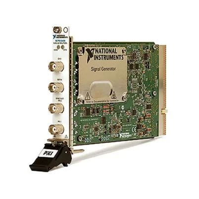
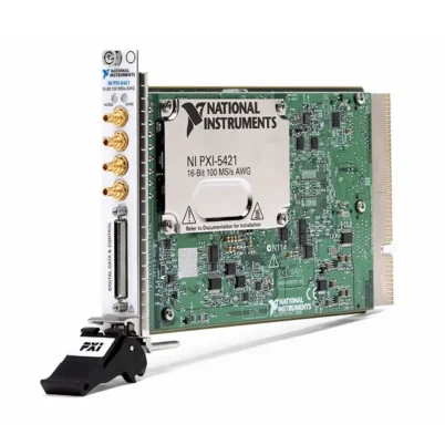
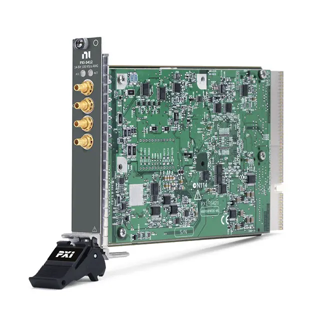
PXI-5412 100 MS/s 14-Bit PXI Arbitrary Waveform Generator
Земля PXI-5412 is a single-channel PXI arbitrary waveform generator designed for automated stimulus generation, electronic device testing, research and mixed-signal validation. It combines a 100 MS/s maximum update rate, 14-bit output resolution и 20 MHz analog bandwidth in a compact, single-slot PXI module.
The PXI-5412 can generate user-defined arbitrary waveforms as well as standard sine, square, triangle and ramp signals. Direct digital synthesis technology provides precise frequency generation, while selectable onboard-memory configurations support both short repetitive signals and longer waveform records.
Key Features of the PXI-5412
- One analog waveform-generation channel
- 100 MS/s maximum update rate
- 14-bit digital-to-analog resolution
- 20 MHz maximum analog bandwidth
- User-defined arbitrary waveform generation
- Sine, square, triangle and ramp generation
- Direct digital synthesis technology
- 8 MB, 32 MB or 256 MB onboard-memory options
- Up to 12 Vpk-pk amplitude into a 50 Ω load
- Up to 24 Vpk-pk amplitude into an open circuit
- Software-selectable 50 Ω or 75 Ω output impedance
- DC-coupled analog output
- Waveform sequencing, looping and triggering
- External sample-clock input
- Two programmable function interface connectors
- PXI triggering and synchronization support
- NI-FGEN driver compatibility
- Single-slot 3U PXI module
PXI-5412 Technical Specifications
| Product Model | PXI-5412 |
|---|---|
| Product Type | PXI arbitrary waveform generator |
| Number of Output Channels | 1 |
| Maximum Update Rate | 100 MS/s |
| DAC Resolution | 14 bits |
| Maximum Analog Bandwidth | 20 MHz |
| Onboard Memory Options | 8 MB, 32 MB or 256 MB |
| Arbitrary Waveform Support | Да |
| Standard Waveforms | Sine, square, triangle and ramp |
| Generation Technology | Direct digital synthesis and arbitrary waveform generation |
| Maximum Amplitude into 50 Ω | 12 Vpk-pk |
| Maximum Amplitude into 1 kΩ | 22.9 Vpk-pk |
| Maximum Open-Circuit Amplitude | 24 Vpk-pk |
| Specified 50 Ω Output Range | Approximately -6 V to +6 V at maximum high-gain amplitude |
| Output Impedance | 50 Ω or 75 Ω nominal, software-selectable |
| Output Coupling | DC |
| Minimum Arbitrary Waveform Size | 4 samples |
| Waveform Quantum | 4 samples |
| Analog Output Connector | CH 0 SMB jack |
| Clock Connector | CLK IN SMB jack |
| Programmable Interfaces | PFI 0 and PFI 1 SMB jacks |
| Шинный интерфейс | PXI; later revisions use a PXI hybrid-compatible connector |
| Module Format | 3U, single-slot PXI module |
| Operating Temperature | 0°C to 55°C |
| Approximate Weight | 340 g |
| Driver | NI-FGEN |
| Life-Cycle Status | Discontinued; verify current support and calibration availability |
| Recommended Replacement | PXIe-5413 |
PXI-5412 Part Numbers and Memory Options
| Part Number | Onboard Memory | Описание |
|---|---|---|
| 779176-01 | 8 MB | PXI-5412 100 MS/s, 14-bit waveform generator with 8 MB memory |
| 779176-02 | 32 MB | PXI-5412 100 MS/s, 14-bit waveform generator with 32 MB memory |
| 779176-03 | 256 MB | PXI-5412 100 MS/s, 14-bit waveform generator with 256 MB memory |
The three PXI-5412 ordering options provide the same output-channel count, bandwidth, update rate and DAC resolution. The primary difference is the amount of onboard waveform memory. Confirm the complete part number when replacing an existing module or expanding a synchronized system.
100 MS/s Arbitrary Waveform Generation
The PXI-5412 updates its 14-bit digital-to-analog converter at rates up to 100 MS/s. This allows the module to reproduce arbitrary voltage patterns with 10 ns sample spacing at the maximum update rate.
User-defined waveforms can represent sensor outputs, communication baseband signals, pulses, transients, ramps and other application-specific stimulus patterns. Waveform quality ultimately depends on the selected update rate, output filter, amplitude range, connected load and frequency content of the uploaded data.
14-Bit Output Resolution
A 14-bit DAC provides 16,384 theoretical output codes across the selected output range. This resolution allows finer amplitude control than lower-resolution waveform generators and helps reproduce detailed analog waveforms for functional and parametric testing.
Usable accuracy is determined by more than DAC resolution. Output-range selection, calibration condition, noise, distortion, offset, cable impedance and load characteristics must also be considered when specifying the complete test system.
20 MHz Analog Bandwidth
The PXI-5412 provides a maximum analog output bandwidth of 20 MHz. It is suitable for DC and low-to-moderate-frequency waveform generation in applications such as analog circuit testing, sensor simulation, control-system stimulus and component characterization.
Signals approaching the bandwidth limit can experience amplitude attenuation and phase shift. For best waveform fidelity, select a sample rate that provides sufficient points per cycle and verify the signal at the device under test with the intended cable and termination.
Direct Digital Synthesis
Direct digital synthesis enables the PXI-5412 to generate standard periodic signals with precise, programmable frequency and phase. DDS operation is useful for producing sine waves, square waves, triangle waves and ramps without storing a long record containing every repeated cycle.
DDS-based generation also supports frequency sweeps and hopping sequences controlled through the NI-FGEN driver. This is useful when a device must be stimulated across multiple operating frequencies during automated characterization.
User-Defined Arbitrary Waveforms
Arbitrary waveform mode allows engineers to create a series of voltage samples and download them to the module. The PXI-5412 then reproduces the samples through its analog output at the configured update rate.
The minimum arbitrary waveform size is four samples, and waveform sizes use a four-sample quantum. This relatively small waveform granularity makes it possible to construct compact repeating patterns while conserving onboard memory.
8 MB, 32 MB and 256 MB Memory Options
The PXI-5412 was offered with three onboard-memory capacities. The 8 MB version is appropriate for standard functions and shorter repeating waveforms. The 32 MB and 256 MB versions support longer records, additional stored waveforms and more complex automated sequences.
Required memory depends on the waveform length, sample representation and number of patterns stored simultaneously. A long-duration signal generated at the full 100 MS/s update rate consumes considerably more memory than a short waveform that is repeatedly looped.
Waveform Sequencing and Looping
The module can arrange stored waveforms into sequences so that multiple stimulus patterns are generated without downloading each waveform again during the test. Individual waveform segments can be repeated to create steady-state periods, bursts or recurring events.
Sequencing can improve test throughput because the required signal records are prepared before generation begins. The test application can then use triggers and software commands to coordinate the signal with measurements or device operating states.
Amplitude and Offset Control
The PXI-5412 contains low-gain and high-gain analog output paths. Into a 50 Ω load, its main output supports amplitudes from millivolt-level ranges up to 12 Vpk-pk. With an open-circuit load, the maximum programmed amplitude can reach 24 Vpk-pk.
The frequently specified -6 V to +6 V output capability describes the maximum high-gain voltage delivered into a correctly terminated 50 Ω load. An open-circuit or high-impedance instrument can measure approximately twice the voltage expected for a 50 Ω termination unless the load setting and cabling are handled correctly.
Software-Selectable Output Impedance
The analog output can be configured for a nominal 50 Ω or 75 Ω source impedance. The 50 Ω setting is commonly used with laboratory instruments and high-frequency test fixtures, while 75 Ω is useful for compatible video and communication systems.
The configured load value must correspond to the actual termination used by the device under test. An impedance mismatch can change the observed amplitude and introduce reflections, ringing or waveform distortion.
DC-Coupled Output
The PXI-5412 provides a DC-coupled output, allowing it to generate signals that include a DC component or programmed offset. This is useful for simulating biased sensor signals, control voltages and asymmetric waveforms.
Before applying an offset, verify the combined peak value of the signal amplitude and offset. The complete waveform must remain within the available output range and the electrical limits of the connected device.
Front-Panel Connections
The module has four front-panel SMB connectors. CH 0 carries the analog waveform output. CLK IN accepts an external sample-clock source, while PFI 0 and PFI 1 provide programmable trigger, marker or event connections according to the configured generation mode.
Use 50 Ω or 75 Ω coaxial cables and adapters appropriate for the selected impedance. SMB connectors should be fully seated, and cable strain should be controlled to protect the front-panel connections.
Triggering and Event Coordination
The PXI-5412 can use software, front-panel and PXI trigger resources to begin or coordinate waveform generation. Triggered operation allows a waveform to start in response to a device-under-test event, another instrument or an automated test-system command.
The programmable function interfaces can also export markers or other generation events. These signals can tell a digitizer, digital instrument or external device when a selected location in the waveform sequence has been reached.
External Clock Input
The CLK IN connector allows the PXI-5412 to accept a compatible external clock. Sharing a reference or sample clock can improve coordination between waveform generators, oscilloscopes and other instruments.
The external clock must meet the electrical, frequency and signal-quality requirements in the PXI-5412 specifications. Excessive jitter or an incorrectly terminated clock can degrade the generated waveform or prevent the module from locking correctly.
PXI Synchronization
Multiple PXI instruments can be synchronized through PXI timing and triggering resources. This makes the PXI-5412 useful in mixed-signal systems where analog stimulus, digital patterns and waveform acquisition must operate from a coordinated timing architecture.
For multichannel generation, use a common reference clock and a supported synchronization procedure. Cable delay, trigger routing, module calibration and chassis timing performance all contribute to the final channel-to-channel alignment.
Typical PXI-5412 Applications
- Electronic device functional testing
- Analog and mixed-signal validation
- Sensor and transducer simulation
- Automotive electronic control-unit testing
- Aerospace and defense system validation
- Frequency-response testing
- Component characterization
- Audio and baseband signal generation
- Production automated test equipment
- Research and laboratory experiments
- Transient and pulse generation
- Closed-loop control-system stimulus
Sensor Simulation
The PXI-5412 can reproduce electrical signals that represent sensor outputs, including slowly changing levels, periodic patterns and recorded transient behavior. This allows a controller to be tested without connecting the physical sensor.
Sensor simulation must account for the electrical behavior expected by the controller. If the real sensor requires isolation, a current output, bridge excitation or a specialized impedance, additional signal-conditioning hardware may be necessary.
Automotive and Aerospace Testing
In controller validation systems, the PXI-5412 can generate deterministic analog stimulus for inputs representing position, speed, pressure, vibration or other operating conditions. Stored waveform sequences can reproduce normal behavior and selected abnormal conditions.
The module itself is not an isolated fault-insertion device. Applications involving shorts, hazardous voltages or high-energy loads require suitable isolation, switching and protection between the generator and the device under test.
Frequency-Response and Component Testing
Software-controlled frequency sweeping can stimulate filters, amplifiers and other analog circuits across a defined frequency range. A synchronized digitizer or digital multimeter can measure the resulting amplitude and phase response.
The PXI architecture allows the generator and measurement instrument to share timing resources and operate as part of one automated sequence. This reduces manual setup and improves repeatability in design validation and production testing.
Production Test Systems
The compact PXI format makes the PXI-5412 suitable for automated production systems requiring repeatable analog stimulus. Test software can select different waveforms, amplitudes, offsets and frequencies for each product or test stage.
When replacing a module in an established system, preserve the memory size, driver configuration, impedance setting, cabling and calibration assumptions used by the original test program.
NI-FGEN Software Support
The PXI-5412 is controlled through the NI-FGEN instrument driver. NI-FGEN provides functions for configuring standard functions, downloading arbitrary waveforms, defining sequences, controlling triggering and starting or stopping generation.
The driver supports automated development through environments such as LabVIEW, LabWindows/CVI and compatible text-based languages. Available language and operating-system support depends on the installed NI-FGEN version.
NI-FGEN Soft Front Panel and InstrumentStudio
Compatible NI-FGEN installations provide an interactive interface for basic setup and troubleshooting. Depending on the driver and operating-system version, this interface may be supplied as an NI-FGEN soft front panel or through InstrumentStudio.
An interactive panel can be used to verify the module, select a waveform, configure amplitude and frequency, enable the output and confirm the basic signal path before integrating the generator into a larger application.
PXI-5412 Troubleshooting
The PXI-5412 is not detected
Confirm that the module is fully installed in a compatible PXI peripheral or hybrid slot. Check chassis power, controller communication and NI-FGEN installation, then use NI Measurement & Automation Explorer to verify device recognition.
No waveform appears at CH 0
Verify that waveform generation has been initiated and that the analog output is enabled. Check the selected trigger mode because the module may be waiting for a trigger. Inspect the SMB cable, output route and connected instrument.
The measured amplitude is twice the expected value
Check whether the waveform was configured for a 50 Ω load but measured with a high-impedance oscilloscope input. Apply the intended 50 Ω termination or configure the generation settings for the actual load.
The waveform is distorted
Confirm that the requested frequency is compatible with the 20 MHz bandwidth and that the selected update rate provides enough samples per cycle. Check the output filter, cable impedance, termination and load capacitance.
The module does not respond to an external trigger
Verify the trigger source, PFI assignment, signal polarity and voltage level. Confirm that the generation session is armed before the trigger arrives and that the external signal shares an appropriate reference with the module.
The external clock does not lock
Check the clock frequency, amplitude, waveform quality and termination against the PXI-5412 input requirements. Inspect the CLK IN connection and confirm that the application selected the correct sample-clock source.
A long waveform cannot be downloaded
Confirm the memory capacity of the installed part-number variant. Reduce the record length or sample rate, divide the signal into reusable waveform segments or use sequence looping to reduce memory consumption.
Multiple modules are not aligned
Use a shared reference clock, coordinated triggers and the synchronization procedure supported by NI-FGEN. Verify that every module has completed initialization and waveform loading before generating the synchronization event.
The output has an unexpected DC offset
Review the programmed offset, amplitude range and waveform data. Disconnect the external load to determine whether the offset originates in the generator, cabling or device under test, and allow the recommended warm-up time before precision measurements.
PXI-5412 Comparison with Related Waveform Generators
| Модель | Primary Configuration | Best Suited For |
|---|---|---|
| PXI-5406 | 40 MHz, 100 MS/s, 16-bit function generator | Standard function and frequency generation |
| PXI-5412 | 20 MHz, 100 MS/s, 14-bit, one-channel AWG | Maintaining legacy PXI arbitrary-waveform systems |
| PXI-5421 | 43 MHz, 100 MS/s, 16-bit AWG | Higher bandwidth and resolution in a legacy PXI platform |
| PXIe-5413 | 20 MHz, 800 MS/s, 16-bit, one or two channels | Modern replacement for PXI-5412 applications |
| PXIe-5423 | 40 MHz, 800 MS/s, 16-bit, one or two channels | Higher-bandwidth precision arbitrary waveform generation |
| PXIe-5433 | 80 MHz, 800 MS/s, 16-bit, one or two channels | Higher-frequency automated waveform generation |
PXI-5412 vs PXIe-5413
The PXI-5412 and PXIe-5413 both provide 20 MHz analog bandwidth, but the newer PXIe-5413 offers 16-bit resolution, an 800 MS/s update rate, one- or two-channel configurations, advanced synchronization and PCI Express waveform streaming.
The PXI-5412 remains useful when maintaining a validated legacy PXI system or replacing an existing module without redesigning the software and fixture. The PXIe-5413 is the recommended choice for new systems when the chassis, driver and application can support PXI Express hardware.
PXI-5412 vs PXI-5421
The PXI-5412 provides 20 MHz bandwidth and 14-bit resolution, while the PXI-5421 increases bandwidth to approximately 43 MHz and resolution to 16 bits. Both products use a 100 MS/s maximum update rate and were offered with multiple onboard-memory sizes.
Choose the PXI-5412 when compatibility with an existing 5412-based test station is essential. Consider the PXI-5421 when the application requires greater bandwidth and vertical resolution while retaining a legacy PXI waveform-generator architecture.
Recommended Related Products
- PXI-5406 Function Generator
- PXI-5421 16-Bit Arbitrary Waveform Generator
- PXIe-5413 20 MHz Arbitrary Waveform Generator
- PXIe-5423 40 MHz Arbitrary Waveform Generator
- PXIe-5433 80 MHz Arbitrary Waveform Generator
- PXIe-5451 High-Speed Arbitrary Waveform Generator
- View More NI PXI and PXI Express Modules
Selecting the Right Waveform Generator
Choose the PXI-5412 when an existing test system requires a one-channel, 20 MHz, 14-bit PXI arbitrary waveform generator with a 100 MS/s update rate. Match the 8 MB, 32 MB or 256 MB memory option to the original module or the required waveform-record length.
For a new test system, consider the PXIe-5413 because it is the recommended replacement and offers higher resolution, a substantially faster update rate, waveform streaming and optional dual-channel operation. Select the PXIe-5423 or PXIe-5433 when the application requires additional analog bandwidth.
Why Choose the PXI-5412?
- Generates both standard and user-defined waveforms
- Provides a 100 MS/s maximum update rate
- Offers 14-bit analog output resolution
- Supports signals through a 20 MHz analog bandwidth
- Provides three onboard-memory configurations
- Supports high-amplitude output into 50 Ω and high-impedance loads
- Integrates with PXI timing and triggering resources
- Supports automated control through NI-FGEN
- Fits legacy single-slot PXI waveform-generation systems
Frequently Asked Questions
What is the PXI-5412?
The PXI-5412 is a single-channel PXI arbitrary waveform generator with a 100 MS/s update rate, 14-bit resolution and 20 MHz maximum analog bandwidth.
What waveforms can the PXI-5412 generate?
It can generate user-defined arbitrary waveforms and standard functions including sine, square, triangle and ramp signals.
What is the maximum update rate?
The maximum waveform update rate is 100 MS/s.
What is the output resolution?
The PXI-5412 uses a 14-bit digital-to-analog converter.
How many output channels does it have?
The module provides one analog output channel through the front-panel CH 0 SMB connector.
What is the maximum output amplitude?
The high-gain path supports up to 12 Vpk-pk into a 50 Ω load and up to 24 Vpk-pk into an open circuit. The programmed load and actual termination must be configured correctly.
Which memory options are available?
The PXI-5412 was offered with 8 MB, 32 MB or 256 MB of onboard waveform memory.
What are the PXI-5412 part numbers?
Part number 779176-01 has 8 MB memory, 779176-02 has 32 MB and 779176-03 has 256 MB.
Does the PXI-5412 support arbitrary waveforms?
Yes. Users can create waveform sample arrays, download them to onboard memory and generate them at a programmable update rate.
Which driver controls the PXI-5412?
The module is controlled through the NI-FGEN instrument driver. Verify operating-system and development-environment compatibility with the specific NI-FGEN release being installed.
Is the PXI-5412 still available from NI?
No. NI identifies the PXI-5412 as no longer available. Availability may be limited to existing inventory and used or refurbished equipment.
What is the recommended replacement?
The recommended replacement is the PXIe-5413, a 20 MHz, 16-bit PXI Express arbitrary waveform generator available with one or two output channels.
Request a Quote for the PXI-5412
Contact us for current availability, configuration verification and project pricing for the PXI-5412 100 MS/s 14-Bit PXI Arbitrary Waveform Generator. Please specify whether the application requires part number 779176-01, 779176-02 or 779176-03 so the correct onboard-memory capacity can be supplied.















