






Показаны все (4)

Фильтр по цене
Фильтровать по брендам

- Национальные инструменты
- PCI ModulesPCI Modules
- Системы PXI
- PXI Шасси
- PXI Контроллер
- Модули PXI
- PXI Semiconductor Test
- PXI FPGA and RIO Modules
- PXI MXI Interfaces
- PXI Programmable Power Supplies & SMU
- PXI Sensor Measurements
- Генераторы сигналов PXI
- PXI Vision
- Сбор данных PXI
- Осциллографы/Цифровые преобразователи PXI
- PXI Счетчики/Таймеры
- PXI РЧ и беспроводное тестирование
- PXI GPIB, Ethernet and VXI
- PXI-коммутаторы
- Цифровые мультиметры PXI
- Цифровой ввод-вывод PXI
- Промышленная связь PXI
- Динамический анализ сигналов PXI
- Передача данных PXI
- CompactDAQ Systems
- CompactRIO Systems
- PCI Modules
- USB Devices
- Устройство программно-определяемого радио USRP
- ключи
- ТекТроникс



NI PCI High-Speed Digitizers
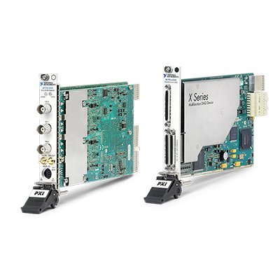
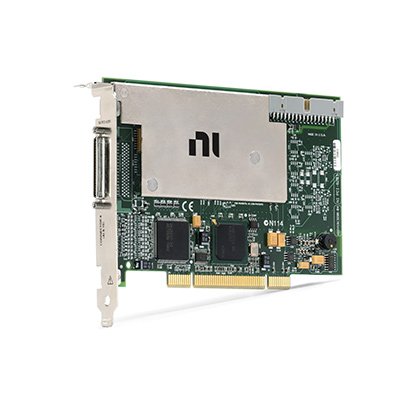
NI PCI High-Speed Digitizers are computer-based oscilloscope devices designed for automated waveform acquisition, transient recording, frequency-domain analysis and production test. Installed directly in a compatible computer, these digitizers combine high-speed analog-to-digital conversion, hardware triggering, onboard waveform memory and NI-SCOPE software support.
NI PCI digitizers range from high-channel-count instruments to high-resolution and gigasample-per-second architectures. Selecting the correct device requires balancing analog bandwidth, real-time sample rate, ADC resolution, channel count, input range, onboard memory, triggering, PCI compatibility and software support.
What Is a PCI High-Speed Digitizer?
A PCI high-speed digitizer converts analog voltage waveforms into digital samples for transfer, processing and storage by a host computer. It performs many of the measurement functions of a digital oscilloscope but is optimized for integration into automated test systems.
A typical PCI digitizer includes:
- One or more high-speed analog input channels
- Analog front-end amplification and attenuation
- Selectable input ranges, coupling and impedance
- High-speed analog-to-digital converters
- Onboard waveform memory
- Hardware triggering and timestamp-related functions
- A conventional PCI interface to the host computer
- NI-SCOPE instrument driver and software APIs
Unlike a standalone oscilloscope, a PCI digitizer normally relies on the computer for its display, user interface, data analysis, file storage and test sequencing. This architecture is well suited to automated measurement systems that must process large quantities of waveform data or coordinate acquisition with other instruments.
Representative NI PCI Digitizer Architectures
| Модель | Unique Category | Core Architecture | Best Fit |
|---|---|---|---|
| PCI-5105 | High-Channel-Count Digitizer | Eight simultaneously sampled channels, 12-bit resolution and sampling rates up to 60 MS/s per channel | Multichannel waveform acquisition and synchronized component testing |
| PCI-5122 | High-Resolution Digitizer | Two channels, 14-bit resolution, 100 MS/s sampling and 100 MHz analog bandwidth | Precision transient capture, spectral analysis and communications testing |
| PCI-5154 | High-Sample-Rate Digitizer | Two-channel oscilloscope architecture with sampling rates up to 2 GS/s | Fast-edge characterization, pulse measurements and high-frequency waveform capture |
| PCI-5922 | Flexible-Resolution Digitizer | Two-channel architecture with measurement resolution up to 24 bits and sampling rates up to 15 MS/s | Low-distortion, audio, spectral and precision time-domain measurements |
These models represent different digitizer architectures rather than interchangeable performance levels. A higher sample rate does not automatically provide better amplitude accuracy, while a higher resolution device may not provide the bandwidth required for fast pulses.
Many conventional PCI digitizers were designed for earlier workstation and operating-system generations. Before ordering, verify the exact PCI slot type, card dimensions, available cooling, operating system, NI-SCOPE version and application-software compatibility.
How to Select a PCI High-Speed Digitizer
1. Determine the Required Analog Bandwidth
Analog bandwidth defines the input frequency range over which the digitizer maintains its specified amplitude response. It should be selected according to the highest signal frequency and the rise time that must be measured.
For sine-wave measurements, the digitizer bandwidth should exceed the highest frequency component of interest. Pulse and digital-edge measurements may require substantially more bandwidth because a square wave contains multiple harmonics.
An approximate relationship between bandwidth and the fastest measurable rise time is:
Rise time ≈ 0.35 ÷ analog bandwidth.
This estimate depends on the instrument response and should be supplemented with the exact bandwidth and rise-time specifications of the selected model.
2. Select the Real-Time Sample Rate
Sample rate determines how frequently the analog input is converted into digital values. A higher sample rate provides more samples across a waveform and improves the representation of fast transients.
The Nyquist criterion requires a sample rate greater than twice the highest signal frequency, but practical waveform analysis normally requires additional margin. Pulse shape, timing accuracy, interpolation and digital filtering should all be considered.
Check whether the published maximum rate applies to every channel simultaneously or only to a specific channel configuration. Real-time sampling should also be distinguished from equivalent-time or random-interleaved sampling, which is intended for repetitive signals.
3. Balance Resolution and Speed
ADC resolution determines the number of available amplitude codes. An 8-bit digitizer provides 256 theoretical codes, while a 14-bit digitizer provides 16,384. Higher resolution can improve the ability to identify small waveform details when the input range and noise performance are appropriate.
Resolution alone does not define measurement quality. Input noise, signal-to-noise ratio, effective number of bits, distortion, bandwidth, input range and calibration accuracy must also be reviewed.
High-sample-rate digitizers are generally selected for fast transitions and wideband signals. High-resolution or flexible-resolution digitizers are more appropriate when amplitude fidelity, dynamic range or spectral purity is the primary requirement.
4. Select the Channel Count
Determine how many signals must be acquired at the same time. Simultaneously sampled channels are important for phase, propagation-delay and timing measurements because each channel uses a synchronized acquisition path.
When several digitizers are installed in one computer, confirm how their reference clocks and triggers will be shared. Installing multiple boards does not automatically guarantee phase-aligned sampling.
5. Match the Input Range
Select the smallest input range that accommodates the complete expected waveform, including offset, noise and possible overshoot. Using an unnecessarily large range reduces the portion of the ADC span used by the signal.
Review the available voltage ranges, allowable offset, maximum input voltage and overload behavior. The signal must remain within both the configured measurement range and the absolute input limits.
6. Verify Input Impedance and Coupling
High-speed digitizers may provide selectable 50 Ω and 1 MΩ input impedance. The correct setting depends on the signal source and cabling arrangement.
- 50 Ω input: Used with controlled-impedance coaxial systems and sources designed to drive a 50 Ω load.
- 1 MΩ input: Used for higher-impedance sources and compatible oscilloscope probes.
- DC coupling: Preserves both the AC waveform and its DC offset.
- AC coupling: Blocks the DC component so smaller AC variations can be measured around zero.
Incorrect termination can change the measured amplitude, create reflections or overload the source. Confirm whether the source specification assumes an open circuit or a terminated 50 Ω load.
7. Calculate the Required Record Length
Onboard memory determines how long a waveform can be recorded at a selected sample rate:
Record duration = samples per channel ÷ sample rate.
For example, a higher sample rate consumes the available waveform memory more quickly. Pretrigger samples, multiple records, channel count and instrument overhead should be included when calculating the required memory.
Deep onboard memory is especially important for long transient events, protocol packets, segmented acquisitions and measurements that cannot be continuously transferred through the PCI bus at the full acquisition rate.
8. Review Trigger Requirements
Hardware triggering allows the digitizer to capture a waveform relative to a defined event. Depending on the model, supported trigger functions may include edge, window, hysteresis, pulse-width, digital and external triggering.
Important trigger specifications include:
- Trigger source
- Trigger level and range
- Trigger sensitivity
- Trigger delay
- Pretrigger and posttrigger record length
- Trigger holdoff
- Trigger jitter
- Multiple-record acquisition support
Use multiple-record acquisition when many short events must be captured with minimal dead time and the intervals between events do not need to be stored as continuous waveform data.
Finite Acquisition and Continuous Streaming
PCI digitizers commonly support finite acquisitions in which waveform data is first captured into onboard memory and then transferred to the host computer. This approach is appropriate for triggered events and records that fit within the installed memory.
Continuous acquisition transfers waveform data while sampling continues. The required payload rate can be estimated as:
Data rate = active channels × sample rate × transferred bytes per sample.
The transferred sample format may use more bits than the ADC resolution. Include record headers, timestamps and software overhead when estimating the required PCI bandwidth and storage performance.
Continuous streaming depends on the complete data path:
- Digitizer acquisition and transfer architecture
- Conventional PCI bus bandwidth
- Other devices sharing the PCI bus
- Host memory and processor performance
- NI-SCOPE buffer configuration
- Application read-block size
- Disk sustained-write performance
- File format and processing workload
A digitizer’s maximum sample rate may be much higher than the sustained PCI transfer rate. Onboard memory, segmented acquisition, decimation or reduced channel configurations may therefore be required.
Understanding Digitizer Performance Specifications
| Спецификация | What It Describes | Why It Matters |
|---|---|---|
| Analog Bandwidth | Frequency range supported by the analog input path | Determines measurable signal frequency and edge response |
| Real-Time Sample Rate | Number of samples acquired per second during one event | Controls time resolution and samples per waveform cycle |
| ADC Resolution | Number of theoretical amplitude codes | Affects quantization step size and potential dynamic range |
| Effective Number of Bits | Usable resolution after noise and distortion are considered | Better represents real measurement performance than nominal resolution alone |
| SNR | Ratio between the measured signal and broadband noise | Important for detecting small waveform components |
| SFDR | Difference between the desired signal and the largest spurious component | Important for spectral and communications measurements |
| Onboard Memory | Local storage available for acquired waveform records | Determines finite record length and multirecord capacity |
| Channel Skew | Timing difference between simultaneously sampled channels | Affects phase and propagation-delay measurements |
| Input Range | Full-scale voltage span applied to the ADC path | Controls signal utilization of the available converter range |
PCI Digitizer, DAQ Device or Standalone Oscilloscope?
| Instrument Type | Primary Strength | Typical Limitation | Best Fit |
|---|---|---|---|
| PCI High-Speed Digitizer | Automated waveform acquisition, deep memory and software integration | Requires a compatible computer, driver and custom application | Production test and PC-based measurement systems |
| Multifunction DAQ Device | Mixed analog, digital and counter functions | Usually provides less waveform bandwidth and specialized oscilloscope triggering | General laboratory and industrial data acquisition |
| Dynamic Signal Acquisition Device | High dynamic range and integrated anti-alias filtering | Lower maximum bandwidth than many high-speed digitizers | Audio, acoustic and vibration measurements |
| Standalone Oscilloscope | Integrated display, controls, probes and interactive debugging | May require additional programming for large automated systems | Bench troubleshooting and manual waveform inspection |
| PXI/PXIe Digitizer | Modular synchronization, triggering and multidevice scalability | Requires a compatible PXI chassis and controller | High-channel-count and synchronized automated test |
Choose a PCI digitizer when direct installation in an existing computer is required and its performance, software and lifecycle match the application. Consider PXI Express when the system requires greater modularity, multichannel synchronization or a newer high-throughput platform.
Probes, Cables and Signal Connectivity
The measurement path includes the signal source, probe or cable, termination, adapter and digitizer input. Each component must support the required bandwidth and voltage.
Review the following accessories:
- 50 Ω coaxial cables with the required frequency rating
- Compatible passive or active probes
- High-voltage differential probes
- Current probes and compatible amplifiers
- Attenuators and impedance-matching networks
- BNC adapters and breakout cables
- External trigger and reference-clock cables
Probe attenuation and input impedance must be reflected in the software scaling. Cable loss, reflections and connector quality become increasingly important as signal frequency and edge speed increase.
Never connect a signal that exceeds the digitizer’s maximum input rating. Use an appropriately rated attenuator, probe, isolation device or differential measurement solution when working with high voltage, floating circuits or hazardous energy.
Synchronization and Multidevice Measurements
Applications using multiple digitizers may require a shared reference clock, sample clock, start trigger or reference trigger. The required method depends on whether the goal is synchronized acquisition start, matched sample timing or phase-coherent measurement.
Conventional desktop computers do not provide the dedicated timing and trigger buses found in PXI systems. External cabling and supported synchronization methods may be required between PCI boards.
Before configuring a multidevice system, determine:
- Required channel-to-channel timing accuracy
- Whether devices must share one reference clock
- Trigger distribution direction and loading
- Expected cable propagation delay
- Whether software-based alignment is acceptable
- Calibration requirements for amplitude and timing
NI-SCOPE Software Support
NI PCI high-speed digitizers are generally controlled through NI-SCOPE. NI-SCOPE provides an instrument driver, configuration functions, waveform acquisition APIs, examples and a soft front panel for supported devices.
Depending on the installed driver version, applications may be developed using LabVIEW, LabWindows/CVI, C/C++, .NET or other supported environments. TestStand can call digitizer measurement code as part of automated test sequences.
NI Measurement & Automation Explorer can be used to confirm device detection, inspect hardware resources and perform supported self-test or configuration functions.
Before purchasing a legacy PCI digitizer, verify:
- Exact NI-SCOPE version supporting the device
- Windows and operating-system compatibility
- 32-bit or 64-bit application requirements
- LabVIEW or development-environment compatibility
- Existing source-code dependencies
- Required analysis or test-software licenses
- Availability of the correct installer and documentation
Typical PCI High-Speed Digitizer Applications
- Electronic component and circuit validation
- Automated production testing
- Transient and pulse capture
- Power-supply and power-electronics measurements
- Communications waveform analysis
- Time-of-flight and propagation-delay measurements
- Ultrasonic and nondestructive testing
- LIDAR and optical measurement systems
- Radar and pulsed-signal acquisition
- Medical and scientific instrumentation
- Spectral, distortion and noise analysis
- Multichannel waveform recording
Legacy PCI Digitizer Replacement
Replacing a legacy PCI digitizer requires more than matching bandwidth and sample rate. A newer PCIe, PXI or USB instrument may use a different driver version, trigger connector, memory architecture, input range or programming behavior.
Compare the following before approving a replacement:
- PCI, PCI Express, PXI or USB form factor
- Analog bandwidth and input rise time
- Real-time sample rate and channel configuration
- ADC resolution and dynamic performance
- Input range, impedance and coupling
- Maximum input voltage
- Onboard memory and record architecture
- Trigger modes and trigger latency
- Reference-clock and synchronization connections
- NI-SCOPE API and attribute compatibility
- Operating-system and development-software support
- Connector, cable and probe compatibility
Even when two digitizers use NI-SCOPE, application changes may be required because supported ranges, timing attributes, memory sizes and trigger capabilities differ. Validate the replacement with the original signals, acquisition settings and test limits before production use.
PCI High-Speed Digitizer Procurement and RFQ Guide
Provide the following information for accurate product selection and quotation:
- Required NI model and complete part number
- Signal type and maximum input voltage
- Required analog bandwidth
- Required real-time sample rate
- Minimum ADC resolution or dynamic range
- Number of simultaneously sampled channels
- Required record length or acquisition duration
- Trigger type and pretrigger requirements
- Finite, multirecord or continuous acquisition mode
- Host-computer model and available PCI slots
- Operating system and NI-SCOPE version
- LabVIEW, TestStand or other application-software version
- Required probes, cables and connector accessories
- New or pre-owned hardware preference
- Required quantity, destination and delivery date
For pre-owned digitizers, request device-recognition results, self-test status, channel acquisition testing, trigger verification and inspection of the PCI edge connector and input connectors. Device detection alone does not verify analog accuracy, bandwidth or every acquisition function.
Часто задаваемые вопросы
What is the difference between analog bandwidth and sample rate?
Analog bandwidth describes the frequency response of the input path. Sample rate describes how many digital samples are acquired each second. Both must support the signal being measured; a high sample rate cannot compensate for insufficient analog bandwidth.
Is a high-speed digitizer the same as an oscilloscope?
A high-speed digitizer provides oscilloscope-type waveform acquisition, triggering and input conditioning but normally relies on a host computer for display, analysis and automation. A standalone oscilloscope integrates these functions into one instrument.
Can a PCI digitizer stream continuously at its maximum sample rate?
Not necessarily. The maximum ADC sample rate may exceed the sustained transfer capability of the PCI bus, computer memory or storage system. Onboard memory, shorter records, reduced channel count or data reduction may be required.
Why is onboard memory important?
Onboard memory stores waveform samples before they are transferred to the computer. More memory supports longer finite records, additional pretrigger data and larger multiple-record acquisitions.
Can conventional PCI digitizers be installed in PCIe slots?
No. Conventional PCI and PCI Express use different electrical interfaces and physical connectors. A computer must provide a compatible PCI slot unless a validated expansion or bridging solution is used.
Can multiple PCI digitizers be synchronized?
Synchronization may be possible using supported external reference clocks and trigger connections. The available accuracy and configuration depend on the exact models. A PCI computer does not provide the dedicated synchronization buses available in PXI systems.
Which driver controls NI PCI digitizers?
Supported NI high-speed digitizers normally use NI-SCOPE. Confirm that the exact device is supported by the selected NI-SCOPE version, operating system and development environment.
Should I select the digitizer with the highest resolution?
Not automatically. Higher resolution is useful for amplitude fidelity and dynamic range, but the selected device must also provide sufficient bandwidth, sample rate, channel count and trigger capability.
Related NI Measurement Platforms
Review NI PCI and USB devices for additional PC-based data acquisition and instrumentation. For modular synchronized digitizer systems, explore NI PXI systems. For portable multichannel acquisition with sensor-specific conditioning, consider CompactDAQ systems.
NI PCI High-Speed Digitizers from PXISOURCE
PXISOURCE supports engineers, system integrators and procurement teams with NI PCI digitizer selection, legacy model replacement, host-computer compatibility review, accessory matching and sourcing for automated waveform measurement systems. Send the required model, signal bandwidth, sample rate, channel count, record length, computer configuration and software version for a technically matched quotation.
Need help selecting an NI PCI high-speed digitizer? Email sales@pxisource.com or contact PXISOURCE on WhatsApp.