




Показаны все (2)

Фильтр по цене
Фильтровать по брендам

- Национальные инструменты
- Системы PXI
- PXI Шасси
- PXI Контроллер
- Модули PXI
- PXI Semiconductor Test
- PXI FPGA and RIO Modules
- PXI MXI Interfaces
- PXI Programmable Power Supplies & SMU
- PXI Sensor Measurements
- Генераторы сигналов PXI
- PXI Vision
- Сбор данных PXI
- Осциллографы/Цифровые преобразователи PXI
- PXI Счетчики/Таймеры
- PXI РЧ и беспроводное тестирование
- PXI GPIB, Ethernet and VXI
- PXI-коммутаторы
- Цифровые мультиметры PXI
- Цифровой ввод-вывод PXI
- Промышленная связь PXI
- Динамический анализ сигналов PXI
- Передача данных PXI
- CompactDAQ Systems
- CompactRIO Systems
- PCI Modules
- USB Devices
- Устройство программно-определяемого радио USRP
- Системы PXI
- ключи
- ТекТроникс

NI PXI Digital Multimeters
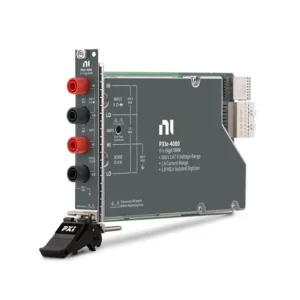
NI PXI Digital Multimeters are precision electrical measurement instruments designed for automated validation, production test, component characterization and laboratory systems. They combine conventional digital multimeter functions with PXI Express triggering, synchronization, software automation and switch integration.
PXI DMMs can measure DC and AC voltage, DC and AC current, 2-wire and 4-wire resistance, frequency, period, diodes and temperature with supported sensors. Selected NI FlexDMM models also include an isolated digitizer for capturing voltage or current waveforms at rates up to 1.8 MS/s.
Selecting the correct module requires more than comparing display digits. Engineers should evaluate the actual ranges, accuracy, resolution, aperture time, reading rate, input loading, burden voltage, resistance configuration, digitizer performance, safety limits, calibration requirements and compatibility with the complete PXI system.
What Is a PXI Digital Multimeter?
A PXI Digital Multimeter, or PXI DMM, is a modular instrument installed in a compatible PXI or PXIe chassis. It is controlled by an embedded PXI controller or an external computer connected through a supported remote-control interface.
Unlike a handheld or standalone bench multimeter, a PXI DMM is optimized for programmable test sequences. It can coordinate measurements with switches, programmable power supplies, source measure units, signal generators and other PXI instruments without requiring an operator to reconnect the DUT manually.
A typical automated sequence may power the DUT, route a test point through a switch matrix, select the appropriate DMM range, wait for settling, perform the measurement and compare the result against a pass/fail limit. The sequence can then advance automatically through hundreds of test points or multiple DUTs.
PXI DMM Measurement Functions
| Measurement | Типичные применения | Important Selection Factors |
|---|---|---|
| DC Voltage | Power rails, reference voltages, batteries, sensor outputs and PCB test | Input range, accuracy, input resistance, offset, noise and common-mode conditions |
| AC Voltage | Power signals, ripple, low-frequency AC circuits and RMS measurements | Frequency range, waveform shape, crest factor, amplitude and AC accuracy |
| DC and AC Current | Power consumption, bias current, load current and circuit verification | Current range, burden voltage, fuse protection, accuracy and maximum input |
| 2-Wire Resistance | General resistors, continuity, sensors and medium- or high-value resistance | Test current, range, lead resistance and fixture resistance |
| 4-Wire Resistance | Contacts, shunts, cables, connectors and low-value resistors | Kelvin routing, switch topology, offset compensation and thermal EMF |
| Frequency and Period | Clock verification, low-frequency signals and repetitive waveform testing | Frequency range, input amplitude, trigger sensitivity and signal shape |
| Temperature | Component, enclosure and environmental temperature verification | Sensor type, wiring, cold-junction compensation, lead resistance and self-heating |
| Diode Test | Semiconductor junction, polarity and forward-voltage verification | Test current, voltage range and required test limits |
| Digitizer Mode | Startup behavior, inrush current, voltage sag and switching transients | Sample rate, analog bandwidth, input range, coupling and record duration |
Measurement functions vary by model. Inductance and capacitance are available on selected NI DMM platforms but are not standard functions of every PXI DMM. Confirm the complete measurement list before selecting or replacing a module.
Current NI PXI Digital Multimeter Models
| Модель | Unique Category | Core Specifications | Best Fit |
|---|---|---|---|
| PXIe-4080 | General-Purpose 6½-Digit PXIe DMM | 6½-digit resolution, ±300 V maximum voltage range, current ranges up to 1 A, maximum scalar reading rate of 20 kS/s and onboard 1.8 MS/s isolated voltage/current digitizer | Automated functional test, production ATE, switch scanning and general precision electrical measurement |
| PXIe-4081 | High-Accuracy 7½-Digit PXIe DMM | 7½-digit resolution, voltage ranges up to ±1,000 V, current ranges up to 3 A, maximum scalar reading rate of 20 kS/s and onboard 1.8 MS/s isolated voltage/current digitizer | Precision characterization, calibration-oriented systems, low-level measurements and higher-voltage applications |
Both modules occupy one PXIe peripheral slot and support precision scalar measurements together with isolated waveform digitization. The PXIe-4080 is a strong general-purpose choice for automated electrical test, while the PXIe-4081 adds higher resolution, wider voltage and current capability and improved performance for demanding precision measurements.
PXIe-4080 vs PXIe-4081
| Selection Point | PXIe-4080 | PXIe-4081 |
|---|---|---|
| Разрешение | 6½ digits | 7½ digits |
| Maximum Voltage Range | ±300 V | ±1,000 V |
| Maximum Current Range | 1 A | 3 A |
| Maximum Scalar Reading Rate | 20 kS/s under specified fast-reading settings | 20 kS/s under specified fast-reading settings |
| Isolated Digitizer | Up to 1.8 MS/s | Up to 1.8 MS/s |
| Primary Selection Reason | General automated electrical measurement and production test | Higher resolution, low-level precision and higher voltage or current ranges |
The PXIe-4081 should not be selected solely because it has more digits. If the PXIe-4080 already meets the required uncertainty, range and throughput, it may be the more appropriate system choice. Select the PXIe-4081 when the additional resolution or extended ranges materially improve the measurement.
How to Select a PXI Digital Multimeter
1. Define Every Required Measurement
Begin with a complete list of DUT parameters: DC voltage, AC voltage, current, resistance, frequency, diode, temperature or transient waveform acquisition. Record the minimum and maximum expected values and the uncertainty required at each test point.
If the application also requires controlled voltage or current sourcing, compliance limits or I-V sweeps, add a PXI programmable power supply or SMU. A DMM measures electrical quantities but is not a complete substitute for a source measure unit.
2. Separate Resolution From Accuracy
Resolution describes the smallest change the DMM can represent. Accuracy describes how closely the result is expected to agree with the true value under defined conditions. A higher digit count can reveal smaller changes, but it does not independently define measurement uncertainty.
The usable result is affected by the selected range, gain and offset errors, temperature, aperture, noise, calibration age, cabling and switching path. Compare accuracy specifications at the actual signal level instead of comparing digit count alone.
3. Select the Correct Voltage and Current Ranges
The selected range must accommodate the maximum normal signal and any expected transient or fault condition. Using the smallest suitable range normally improves effective resolution, while choosing a range that is too small causes an overrange condition.
For current measurements, also evaluate burden voltage. The DMM introduces a voltage drop while measuring current, and that drop can change the DUT operating point in low-voltage or low-power circuits. Very small leakage-current measurements may require an SMU or electrometer-style instrument.
4. Calculate the Required Measurement Uncertainty
A practical uncertainty budget can include DMM accuracy, range contribution, temperature coefficient, measurement noise, calibration interval, test leads, relay contacts, fixture resistance, thermal EMF and DUT settling. The combined uncertainty should be sufficiently smaller than the permitted DUT tolerance.
Production test limits may require guard bands so that measurement uncertainty does not create unacceptable false passes or false failures. Define these requirements before choosing between a general-purpose and higher-accuracy DMM.
5. Balance Aperture Time, NPLC and Throughput
A longer measurement aperture generally reduces noise and improves rejection of power-line interference. DMM integration time is often expressed in number of power-line cycles, or NPLC. Integration matched to the local 50 Hz or 60 Hz supply can improve line-noise rejection.
Shorter apertures increase reading speed but may increase noise and reduce effective resolution. The maximum published reading rate normally assumes fast settings such as disabled auto-zero, minimum aperture and no added settling time. Benchmark the intended configuration rather than treating the maximum rate as the guaranteed application throughput.
6. Choose 2-Wire or 4-Wire Resistance
A 2-wire measurement includes resistance from the test leads, connectors, switch contacts and fixture. It is generally suitable when these contributions are insignificant compared with the DUT resistance.
A 4-wire Kelvin measurement uses separate force and sense connections so voltage drop in the force leads has much less influence on the result. It is recommended for low-value resistors, shunts, relays, connectors, cables and PCB conductors.
If switching is used, the complete path must support four-wire routing. Installing a four-wire-capable DMM does not create a Kelvin measurement when the switch or fixture only routes two conductors.
7. Determine Whether Digitizer Mode Is Required
The PXIe-4080 and PXIe-4081 can acquire isolated voltage or current sample records at up to 1.8 MS/s. This is useful when a scalar reading does not show enough information about how the signal changes over time.
Digitizer mode can be used to analyze power-up behavior, inrush current, relay switching, voltage sag, overshoot and other moderate-bandwidth events. Review both sample rate and analog bandwidth, because a high sampling rate does not guarantee that all high-frequency signal content will pass through the input circuitry.
For fast edges, high-frequency signals or advanced waveform triggering, select a dedicated PXI oscilloscope or digitizer.
8. Check Electrical Safety and Common-Mode Limits
Maximum input voltage is not the only safety specification. Confirm the measurement category, terminal-to-ground voltage, common-mode voltage, input protection, fuse rating and permitted environmental conditions.
PXIe-4080 and PXIe-4081 must not be used for Measurement Category III or IV circuits. High-energy distribution systems, mains installations and field wiring may require instruments with a different safety architecture. Always follow the product documentation and applicable laboratory safety procedures.
9. Plan Switching and Channel Expansion
One DMM can measure many DUT channels when combined with a suitable PXI switch. The switch routes each test point to the DMM sequentially, reducing instrument count in high-channel-count systems.
Total scan time depends on more than DMM reading rate. Include relay operation, contact bounce, signal settling, autoranging, aperture time, auto-zero, trigger latency and software overhead. High-impedance signals may require significantly more settling time after switching.
10. Verify Chassis, Software and Calibration
The PXIe-4080 and PXIe-4081 require PXI Express-compatible peripheral slots. A classic PXI-only slot cannot accept a PXIe module. Check the chassis slot map, controller, operating system and supported driver versions before ordering.
NI-DMM provides programmatic configuration and acquisition functions. InstrumentStudio supports interactive setup and measurement, while LabVIEW and TestStand can be used to create automated validation and production-test applications.
Both measurement performance and traceability depend on calibration conditions. Confirm the required calibration interval, documentation, traceability, warm-up period and whether system-level verification is needed after the module is installed with its cables, switches and fixture.
PXI DMM, DAQ, Digitizer or SMU?
| Instrument Type | Primary Strength | Choose It When |
|---|---|---|
| PXI Digital Multimeter | Precision scalar voltage, current and resistance measurements | Accuracy, electrical measurement functions and switch scanning are priorities |
| PXI Data Acquisition Module | Multichannel acquisition of conditioned voltage and sensor signals | Channel count and synchronized continuous acquisition are more important than DMM functions |
| PXI Oscilloscope/Digitizer | High-speed waveform capture and transient analysis | Bandwidth, timing, waveform shape and advanced triggering are primary requirements |
| PXI SMU | Precision sourcing and measurement with compliance control | The DUT requires I-V sweeps, controlled biasing or very low-current characterization |
DMM and Switch System Design
Combining a DMM with a multiplexer or matrix switch is one of the most common PXI automated-test architectures. It allows one precision measurement engine to serve tens or hundreds of channels.
When designing the signal path, confirm:
- Maximum switched voltage and current
- 2-wire or 4-wire routing requirements
- Relay contact resistance and thermal EMF
- Signal settling after each switching operation
- Isolation and common-mode limits
- Switch bandwidth and leakage
- Connector and cable pinout
- Hardware trigger and handshaking support
The DMM, switch, cabling and fixture should be treated as one measurement system. A high-accuracy DMM cannot remove errors introduced by unsuitable relays, unstable contacts or incorrectly routed Kelvin connections.
Typical PXI Digital Multimeter Applications
- Automated PCB and electronic assembly functional test
- Semiconductor and component characterization
- Power-supply rail and reference-voltage verification
- Battery, converter and power-electronics validation
- Cable, harness and connector continuity testing
- Relay and contact-resistance measurement
- Automotive and aerospace electronic-system test
- Precision resistance and temperature measurement
- Laboratory automation and calibration-oriented systems
- High-channel-count switch-scanning applications
Legacy PXI DMM Replacement
Older systems may use classic PXI models such as PXI-4065, PXI-4070, PXI-4071 or PXI-4072. Replacing one with a current PXIe module is not necessarily a direct substitution, even when the new instrument provides better headline specifications.
Compare the following before approving a replacement:
- Classic PXI or PXI Express slot compatibility
- Voltage, current and resistance ranges
- Resolution and accuracy at the actual signal level
- Reading rate and aperture configuration
- Digitizer and L/C measurement requirements
- Front-panel connections and cable assemblies
- Trigger routing and switch handshaking
- NI-DMM driver and operating-system support
- Calibration procedure and measurement correlation
- Required test-station requalification
For a validated production system, sourcing the original model may reduce software, fixture and requalification work. For a new platform, migration to PXIe can provide a better foundation for current chassis, controllers and software.
PXI Digital Multimeter Procurement and RFQ Guide
Provide the following information for model selection and quotation:
- Required DMM model and part number, if already selected
- Measurement functions and expected signal ranges
- Required resolution and maximum measurement uncertainty
- Minimum and maximum voltage and current
- 2-wire or 4-wire resistance requirements
- Required reading rate or DUT throughput
- Digitizer sample-rate and bandwidth requirements
- Number of test points and switch topology
- Existing chassis, controller and slot information
- Operating system and NI-DMM version
- Probe, cable, connector and fixture requirements
- Calibration and traceability requirements
- New or pre-owned hardware preference
- Required quantity, destination and delivery date
When comparing quotations, confirm the exact model, product condition, included accessories and calibration documentation. For pre-owned instruments, request device-recognition results, functional measurement testing and inspection of the front-panel and backplane connectors.
Часто задаваемые вопросы
What is the difference between PXIe-4080 and PXIe-4081?
The PXIe-4080 is a 6½-digit DMM with voltage ranges up to ±300 V and current ranges up to 1 A. The PXIe-4081 provides 7½-digit resolution, voltage ranges up to ±1,000 V and current ranges up to 3 A. Both include an isolated 1.8 MS/s voltage and current digitizer.
Does a 7½-digit DMM always provide a better measurement?
No. Additional resolution is useful only when the complete accuracy, noise, range, calibration and test setup support it. A 6½-digit DMM may already exceed the requirements of a general automated functional test.
Can a PXI DMM capture waveforms?
Selected NI FlexDMM models, including PXIe-4080 and PXIe-4081, provide isolated digitizer modes for voltage and current waveform acquisition. Review analog bandwidth as well as sample rate. A dedicated oscilloscope remains preferable for high-speed transient analysis.
When should four-wire resistance be used?
Use four-wire Kelvin measurement when lead, connector, relay or fixture resistance is significant relative to the DUT. Typical examples include shunts, contacts, cables, PCB traces and low-value resistors.
Can one PXI DMM measure hundreds of channels?
Yes. An appropriate multiplexer or matrix switch can route many DUT points sequentially to one DMM. Channel count and throughput depend on the switch topology, settling time, relay speed, measurement aperture and wiring configuration.
Should I use a DMM or SMU for semiconductor testing?
Use a DMM for precision passive measurements of voltage, current and resistance. Use an SMU when the test also requires controlled sourcing, compliance protection, I-V sweeps or very low leakage-current measurement.
Can PXIe-4080 or PXIe-4081 be installed in a classic PXI slot?
No. These are PXI Express modules and require compatible PXIe peripheral or hybrid slots. Confirm the exact chassis slot map before ordering.
Do PXIe-4080 and PXIe-4081 measure capacitance or inductance?
These functions should not be assumed for either model. If L/C measurement is required, select a DMM platform that explicitly supports those functions or use a dedicated LCR meter.
Recommended NI PXI Digital Multimeters
Choose the PXIe-4080 for general 6½-digit automated electrical measurements, switch scanning and production test. Select the PXIe-4081 when the application requires 7½-digit resolution, higher precision, voltage ranges up to ±1,000 V or current ranges up to 3 A.
Related NI PXI Test Solutions
Build a complete automated test system with compatible PXI switches, PXI programmable power supplies and SMUs, PXI oscilloscopes and digitizers, or browse the complete NI PXI Modules category.
NI PXI Digital Multimeters from PXISOURCE
PXISOURCE supports engineers, system integrators, production-test teams and procurement departments with PXI DMM model selection, chassis compatibility review, switch integration, legacy replacement and sourcing for new systems, expansion projects and spare inventory.
Send the required measurement functions, signal ranges, uncertainty, channel count, throughput, chassis model and calibration requirements for a technically matched quotation.
Need help selecting an NI PXI Digital Multimeter? Email sales@pxisource.com or contact PXISOURCE through WhatsApp.