






Отображение единственного товара

Фильтровать по брендам

- Национальные инструменты
- PCI ModulesPCI Modules
- Системы PXI
- PXI Шасси
- PXI Контроллер
- Модули PXI
- PXI Semiconductor Test
- PXI FPGA and RIO Modules
- PXI MXI Interfaces
- PXI Programmable Power Supplies & SMU
- PXI Sensor Measurements
- Генераторы сигналов PXI
- PXI Vision
- Сбор данных PXI
- Осциллографы/Цифровые преобразователи PXI
- PXI Счетчики/Таймеры
- PXI РЧ и беспроводное тестирование
- PXI GPIB, Ethernet and VXI
- PXI-коммутаторы
- Цифровые мультиметры PXI
- Цифровой ввод-вывод PXI
- Промышленная связь PXI
- Динамический анализ сигналов PXI
- Передача данных PXI
- CompactDAQ Systems
- CompactRIO Systems
- PCI Modules
- USB Devices
- Устройство программно-определяемого радио USRP
- ключи
- ТекТроникс
NI PCI Vision Acquisition
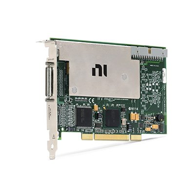
NI PCI Vision Acquisition devices connect industrial and scientific cameras to a host computer for machine vision, automated inspection and high-speed image recording. These PCI and PCI Express frame grabbers acquire image data, manage camera timing and triggers, and transfer frames to computer memory for display, analysis or storage.
NI vision acquisition hardware includes legacy analog video digitizers and digital Camera Link frame grabbers. Correct selection depends on the camera interface, area-scan or line-scan architecture, pixel format, tap configuration, pixel clock, frame rate, trigger requirements, host-bus bandwidth, cable type and NI Vision Acquisition Software compatibility.
What Is a PCI Vision Acquisition Device?
A PCI vision acquisition device, also called a frame grabber, receives image data from an industrial camera and transfers it into computer memory. Unlike a standard display or consumer video-capture card, an industrial frame grabber can support precise triggering, camera control, continuous acquisition and synchronization with inspection equipment.
A typical system includes:
- An area-scan or line-scan industrial camera
- A compatible camera interface and frame grabber
- Camera and trigger cables
- Lens, lighting and optical accessories
- Encoder, sensor or external trigger signals
- A compatible host computer and PCI or PCIe slot
- NI Vision Acquisition Software
- Image-processing or inspection software
The frame grabber handles image transfer and camera-related timing. Image processing, feature measurement, defect classification and inspection decisions are normally performed by host software after acquisition.
PCI Vision Acquisition Interface Types
| Interface Type | Connection Architecture | Primary Advantage | Best Fit |
|---|---|---|---|
| Analog Video | Coaxial or multipin analog camera connection | Supports legacy monochrome, composite and nonstandard analog cameras | Maintaining established inspection and scientific imaging systems |
| Base Camera Link | One Camera Link data cable | Deterministic digital image transfer with camera control and triggering | Standard industrial area-scan and line-scan cameras |
| Medium or Full Camera Link | Normally two Camera Link data cables | Greater data width and higher image throughput | High-resolution, high-frame-rate and multi-tap cameras |
| Power over Camera Link | Camera Link data cable with supported camera power | Can reduce separate camera power wiring | Compatible PoCL cameras and compact installations |
| GigE Vision | Ethernet interface rather than a dedicated frame grabber | Longer cable distance and network-based camera connectivity | Distributed machine vision with moderate bandwidth requirements |
| USB3 Vision | USB 3.x host-controller connection | Simple connection and high data throughput over shorter distances | Laboratory, desktop and compact vision systems |
The camera connector alone does not confirm compatibility. Camera Link systems must also match the Base, Medium, Full or extended configuration, connector style, number of cables, pixel clock, tap geometry, bit depth and camera configuration file.
Representative NI PCI Vision Acquisition Devices
| Модель | Unique Category | Core Architecture | Best Fit |
|---|---|---|---|
| PCI-1410 | Analog Monochrome Acquisition | Four analog video inputs with 8- or 10-bit digitization and support for standard and nonstandard monochrome cameras | Legacy RS-170, CCIR, NTSC, PAL, progressive-scan and line-scan systems |
| PCI-1426 | Base Camera Link Acquisition | Conventional PCI frame grabber for Base-configuration Camera Link cameras with external trigger and control I/O | Industrial digital cameras that do not require Medium or Full Camera Link bandwidth |
| PCIe-1429 | Full Camera Link Acquisition | PCI Express frame grabber supporting higher-bandwidth Camera Link camera configurations | High-resolution area-scan and line-scan acquisition |
| PCIe-1433 | Extended Camera Link Acquisition | PCI Express Camera Link frame grabber supporting Base, Medium, Full and extended camera configurations with onboard buffering | High-data-rate machine vision and scientific imaging |
These models represent different camera-interface generations. They should not be selected only by host-bus type or acquisition speed. The exact camera output format and timing must be matched to the frame grabber.
How to Select a PCI Vision Acquisition Device
1. Identify the Camera Interface
Begin with the complete camera manufacturer and model number. Obtain the camera manual and confirm whether its output is analog video, Camera Link, GigE Vision, USB3 Vision, IEEE 1394 or another interface.
An analog frame grabber cannot acquire a Camera Link signal, and a Camera Link board cannot directly acquire GigE Vision or USB3 Vision data. Electrical adapters do not convert between these image-transfer protocols.
2. Determine Area-Scan or Line-Scan Architecture
Area-scan cameras capture a two-dimensional frame during each exposure. They are used for discrete parts, presence inspection, alignment and general imaging.
Line-scan cameras acquire one or more rows of pixels at a time while the object or camera moves. The application reconstructs the lines into a complete image. Line-scan systems require careful synchronization between line acquisition, conveyor motion and encoder signals.
For line-scan selection, record:
- Pixels per line
- Required line rate
- Pixel bit depth
- Number of camera taps
- Encoder resolution
- Expected object speed
- Required trigger and exposure timing
3. Match the Camera Link Configuration
Camera Link cameras may use Base, Medium, Full or extended configurations. The configuration determines the number of data paths, cables and supported throughput.
Base Camera Link normally uses one cable. Medium and Full configurations normally use two. Higher-tap and extended camera modes require a frame grabber explicitly supporting the camera’s data mapping.
Also verify:
- MDR or SDR connector style
- Number of Camera Link connectors
- Pixel clock range
- Number and arrangement of data taps
- Pixel bit depth
- Monochrome or color format
- PoCL support
- Camera serial-control requirements
4. Calculate the Image Data Rate
For an area-scan camera, the approximate uncompressed payload rate is:
Data rate = image width × image height × bytes per pixel × frames per second.
For a line-scan camera:
Data rate = pixels per line × bytes per pixel × lines per second.
Use the transferred or stored pixel width rather than only the sensor bit depth. A 10-bit or 12-bit camera may transfer each pixel in a 16-bit container. Color images, metadata, padding and alignment can further increase the data volume.
The camera interface, frame grabber, PCIe slot, computer memory, processing software and storage system must all sustain the resulting rate.
5. Verify Pixel Clock and Tap Configuration
The pixel clock determines when image data is transferred from the camera. Multi-tap cameras divide pixels among several parallel data paths to increase throughput.
The frame grabber must interpret the tap geometry correctly. An incorrect tap configuration can produce images with interleaved, reversed, shifted or missing pixels even when acquisition starts successfully.
Check the camera documentation for tap order, data-valid signals, line-valid signals, frame-valid signals and any manufacturer-specific timing requirements.
6. Define Triggering Requirements
Industrial vision systems often acquire images in response to a photoelectric sensor, encoder, programmable controller or other test instrument. Hardware triggering provides more repeatable timing than starting each acquisition through host software.
Determine:
- Trigger source and voltage level
- Rising- or falling-edge operation
- Trigger delay
- Required exposure timing
- Debounce or filtering requirements
- Camera-ready and exposure-active signals
- Missed-trigger behavior
- Need for isolated trigger inputs
The frame grabber’s camera-control outputs may be used for exposure, integration or shutter timing when supported by the camera and acquisition configuration.
7. Select Onboard Buffer Capacity
Onboard frame memory or FIFO buffering helps absorb temporary differences between the camera data rate and host-computer transfer rate. It is particularly important for high-speed cameras, burst acquisition and systems with temporary PCIe or processor contention.
Onboard buffering does not replace adequate sustained system throughput. If the host cannot remove or process images quickly enough, buffers will eventually fill and acquisition may stop or frames may be lost.
8. Review PCI or PCI Express Compatibility
Conventional PCI and PCI Express are different interfaces and cannot be installed in the same slot type. Confirm the available connector, lane width, slot power and physical clearance in the host computer.
For PCIe frame grabbers, verify that the selected slot provides at least the electrical lane width required by the board. A physically long connector does not always guarantee that every lane is electrically connected.
Also review:
- Motherboard slot allocation
- PCIe bandwidth shared with other devices
- Graphics-card and storage traffic
- Computer cooling and airflow
- 64-bit memory addressing support
- BIOS configuration
- Operating-system compatibility
Camera Files and Device Configuration
Many Camera Link and nonstandard analog cameras require a camera configuration file. The file describes the image dimensions, timing, tap mapping, pixel format and acquisition behavior expected by the frame grabber.
A camera file should match the exact camera model and operating mode. Changing the camera resolution, tap configuration, pixel clock or bit depth may require a different file or modified settings.
Common signs of an incorrect camera configuration include:
- No image despite an active camera connection
- Timeout during acquisition
- Incorrect image width or height
- Repeated or missing image sections
- Alternating bright and dark pixels
- Reversed tap order
- Incorrect pixel intensity
- Acquisition stopping at higher frame rates
Confirm camera operation with the supported configuration utility before developing the complete inspection application.
Acquisition Modes
| Acquisition Mode | Operation | Best Fit |
|---|---|---|
| Snap | Acquires one image after the operation is initiated | Setup, alignment and occasional inspection |
| Grab | Continuously acquires images into reusable buffers | Live display and continuous processing |
| Sequence | Acquires a defined series of images into multiple buffers | Burst analysis and finite high-speed recording |
| Triggered Acquisition | Captures images in response to hardware events | Production inspection and synchronized experiments |
| Ring Buffer | Continuously cycles through a group of image buffers | Continuous inspection and event capture |
The required buffer count depends on the frame rate, processing time, display load and temporary operating-system delays. High-rate applications should separate acquisition, processing, display and storage into coordinated software tasks.
Triggering, Encoders and System Synchronization
A complete machine vision system may coordinate cameras, lighting controllers, motion axes, encoders, sensors and reject mechanisms. Timing should be designed for the complete inspection sequence rather than only the camera exposure.
Typical signal flow includes:
- A sensor detects the approaching product.
- The frame grabber or controller delays the trigger to the inspection position.
- The camera exposure and strobe lighting are activated.
- The frame grabber transfers the image into memory.
- Vision software processes the image and makes an inspection decision.
- A controller activates the sorting or reject mechanism at the correct position.
Encoder-based line-scan acquisition should use hardware timing so image scale remains consistent as conveyor speed changes. Software-timed line triggering can cause geometric distortion and inconsistent inspection results.
Cameras, Cables and Accessories
The frame grabber is one part of the image-acquisition system. Confirm all required components before ordering:
- Camera manufacturer and exact model
- Camera Link or analog interface cable
- MDR or SDR connector type
- One- or two-cable Camera Link configuration
- PoCL compatibility or external camera power supply
- Trigger and digital I/O breakout cable
- RTSI or other synchronization cable where applicable
- Lens mount and compatible lens
- Lighting and lighting controller
- Encoder, photoelectric sensor or external trigger source
Camera Link cables are not generic network cables. Use cables designed for the required Camera Link configuration, connector style, clock rate and installation environment.
Long cables, cable flexing, poor shielding and incorrect routing can reduce signal integrity. Robotic and moving applications may require high-flex vision cables rated for repeated motion.
Lighting and Optical Considerations
Image quality depends heavily on the lens and lighting. A higher-resolution camera or faster frame grabber cannot correct inadequate contrast, optical blur, motion blur or inconsistent illumination.
Review:
- Field of view
- Required spatial resolution
- Working distance
- Depth of field
- Lens focal length
- Sensor size and lens coverage
- Exposure time
- Object speed and motion blur
- Lighting geometry, color and intensity
- Need for strobed illumination
The required object resolution can be estimated by dividing the field of view by the number of usable sensor pixels. Allow additional pixel coverage for reliable edge detection, measurement or defect classification.
NI Vision Software Compatibility
NI Vision Acquisition Software provides drivers and utilities for acquiring, displaying and saving images from supported camera interfaces. NI frame grabbers generally use the NI-IMAQ driver included with the software package.
NI Measurement & Automation Explorer can be used to detect supported devices, associate camera files, configure acquisition settings and test image capture.
Image acquisition and image analysis are different software functions:
- Vision Acquisition Software: Connects to supported cameras and acquires images.
- Vision Development Module: Provides image-processing, measurement and machine vision functions for custom applications.
- Vision Builder for Automated Inspection: Provides a configurable environment for building and deploying inspection sequences.
Before purchasing legacy vision hardware, verify:
- Vision Acquisition Software version
- NI-IMAQ support for the exact frame grabber
- LabVIEW or development-environment compatibility
- Windows and operating-system support
- 32-bit or 64-bit application requirements
- Availability of the correct camera file
- Vision Development Module or Vision Builder licensing
PCI Frame Grabber Compared with Direct Camera Interfaces
| Interface | Dedicated Frame Grabber | Typical Cable Distance | Primary Selection Reason |
|---|---|---|---|
| Analog Video | Required | Application dependent | Compatibility with legacy industrial cameras |
| Camera Link | Required | Relatively short without extension technology | Deterministic high-speed image transfer and precise triggering |
| GigE Vision | Normally uses a compatible Ethernet interface | Longer network-based connection | Distributed cameras and easier cable routing |
| USB3 Vision | Normally uses a compatible USB host controller | Shorter direct connection | Compact, high-throughput desktop acquisition |
| IEEE 1394 | Uses a compatible FireWire controller | Interface dependent | Maintenance of older digital camera systems |
Typical PCI Vision Acquisition Applications
- Automated optical inspection
- Electronic assembly inspection
- Semiconductor wafer and package inspection
- Surface and defect detection
- Barcode and optical character recognition
- Dimensional measurement
- Robotic guidance and alignment
- High-speed line-scan inspection
- Scientific and microscopic imaging
- Motion and event analysis
- Medical and laboratory imaging
- Packaging and label inspection
- Web, film, paper and textile inspection
Legacy Frame Grabber Replacement
Replacing a legacy PCI vision acquisition board requires more than matching the camera connector. The replacement must support the camera’s electrical interface, data format, timing and software configuration.
Compare the following before approving a replacement:
- Conventional PCI or PCI Express host interface
- Analog or digital camera interface
- Base, Medium, Full or extended Camera Link mode
- Pixel clock and tap configuration
- Pixel depth and color format
- Area-scan or line-scan operation
- Onboard memory and host-transfer bandwidth
- Trigger and camera-control I/O
- PoCL support
- Camera and trigger cable pinout
- Camera configuration file
- NI-IMAQ and Vision Acquisition Software version
- Operating-system and LabVIEW compatibility
- Existing application source code
A newer frame grabber may require new Camera Link cables, trigger accessories, software versions and camera files. Validate frame integrity, trigger timing and sustained acquisition at the intended operating rate before production deployment.
PCI Vision Acquisition Procurement and RFQ Guide
Provide the following information for accurate frame-grabber selection and quotation:
- Required NI model and complete part number
- Camera manufacturer and complete model
- Analog, Camera Link or other camera interface
- Base, Medium, Full or extended Camera Link configuration
- Area-scan or line-scan architecture
- Image width, height and pixel format
- Frame rate or line rate
- Pixel clock and camera tap configuration
- Monochrome or color acquisition
- Trigger, encoder and exposure-control requirements
- PCI or PCIe host-computer slot
- Operating system and Vision Acquisition Software version
- Required camera, trigger and synchronization cables
- New or pre-owned hardware preference
- Required quantity, destination and delivery date
For pre-owned frame grabbers, request device-recognition results, camera acquisition testing, trigger-I/O testing and physical inspection of the computer and camera connectors. Device recognition alone does not confirm reliable full-rate image acquisition.
Часто задаваемые вопросы
What is a frame grabber?
A frame grabber is an interface device that receives image data from an industrial camera, manages acquisition timing and transfers images into computer memory for processing or storage.
Does every machine vision camera require a frame grabber?
No. Analog and Camera Link cameras require compatible acquisition hardware. GigE Vision and USB3 Vision cameras normally use compatible Ethernet or USB host interfaces instead of a dedicated Camera Link frame grabber.
Can a Base Camera Link board acquire from a Full Camera Link camera?
Only if the camera can be configured to transmit a supported Base-mode output. A camera operating in Medium, Full or extended mode requires a frame grabber that supports that configuration.
Why is my Camera Link camera not automatically detected?
Camera Link is not generally a plug-and-play discovery interface. The system may require the correct camera configuration file, serial settings, tap mapping, pixel clock and acquisition parameters.
What is the difference between NI Vision Acquisition Software and the Vision Development Module?
Vision Acquisition Software provides camera connectivity and image acquisition. The Vision Development Module provides image-processing and analysis algorithms for building inspection applications.
Can conventional PCI frame grabbers be installed in PCIe slots?
No. PCI and PCI Express use different physical and electrical interfaces. The host computer must provide the correct slot type or the system must be migrated to compatible hardware.
Why are images lost during continuous acquisition?
Lost frames can result from insufficient PCIe bandwidth, slow image processing, too few buffers, storage limitations, an incorrect camera file or excessive competition for computer resources. Test the complete system at the intended frame rate and duration.
Can a frame grabber power the camera?
Only when both the frame grabber and camera support a compatible power-over-interface standard such as PoCL. Otherwise, the camera requires a separate power supply.
Related NI Test and Measurement Platforms
Review NI PCI and USB devices for additional computer-based acquisition hardware. For modular vision, synchronization and automated test systems, explore NI PXI systems. Additional measurement and control products are available in the NI product catalog.
NI PCI Vision Acquisition Devices from PXISOURCE
PXISOURCE supports engineers, machine builders, system integrators and procurement teams with NI frame-grabber selection, camera compatibility review, legacy replacement, cable matching and sourcing for machine vision and scientific imaging systems. Send the camera model, interface configuration, frame or line rate, host-computer slot and software version for a technically matched quotation.
Need help selecting an NI PCI vision acquisition device? Email sales@pxisource.com or contact PXISOURCE on WhatsApp.