






Quick Answer: To choose a PXI system, first define the device-under-test signals, measurement functions, channel count, sample rate, bandwidth, accuracy, and synchronization requirements. Select the instrument modules before the chassis. Then choose a compatible PXI or PXIe chassis with the correct slots, bandwidth, power, cooling, and timing resources. Finally, select an embedded or remote controller, verify software and driver support, and include all cables, terminal blocks, fixtures, licenses, and calibration in the complete system configuration.
What Is a PXI System?
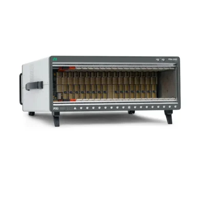
A PXI system is a modular test and measurement platform built from a chassis, controller, instrument modules, software, and accessories. Engineers can combine oscilloscopes, digitizers, DMMs, waveform generators, SMUs, switches, RF instruments, data acquisition modules, FPGA hardware, and communication interfaces in one coordinated system.
The correct configuration is determined by the application. A production functional tester may prioritize channel density, switching, reliability, and test speed. A radar or wireless system may prioritize RF bandwidth, PCI Express throughput, phase coherence, and FPGA processing. A sensor-logging system may need isolation, signal conditioning, accuracy, and long-duration storage.
For this reason, there is no single PXI chassis, controller, or module set that is best for every project. A structured selection process prevents compatibility problems and unnecessary cost.
Choose the PXI System in the Correct Order
Recommended selection order:
- Define the device under test and test objectives.
- List every signal and required test function.
- Select the measurement, generation, switching, and interface modules.
- Decide whether PXI or PXIe is required.
- Calculate slots, bandwidth, power, and cooling.
- Select the chassis and create a slot map.
- Select the embedded or remote controller.
- Design timing and synchronization.
- Verify software, drivers, and operating system.
- Complete the bill of materials with accessories and services.
Choosing a chassis first is a common mistake. The selected modules determine the required slot type, physical width, data throughput, timing resources, power, and cooling. The chassis and controller should be chosen to support those modules as a complete workload.
Step 1: Define the Application
Identify the Device Under Test
Describe what will be tested: a PCB, semiconductor device, RF subsystem, automotive ECU, sensor, power converter, aerospace assembly, communication device, or complete product. Include the number of DUTs tested simultaneously and expected production volume.
Define the Test Objective
Determine whether the system is for research, characterization, design validation, production test, quality inspection, hardware-in-the-loop simulation, data recording, repair, or field service. The objective influences accuracy, speed, automation, environmental design, and lifecycle requirements.
Describe the Operating Environment
Record ambient temperature, rack space, acoustic limits, vibration, dust, airflow, input voltage, grounding, duty cycle, and remote-operation requirements. A quiet laboratory system and a 24/7 production tester may use similar instruments but require different chassis and maintenance strategies.
Functional RequirementsMeasurements, generation, switching, communication, control, and analysis.
Performance RequirementsChannels, sample rate, bandwidth, accuracy, latency, and throughput.
Operational RequirementsAutomation, parallel DUTs, test duration, reporting, and uptime.
Environmental RequirementsTemperature, rack size, noise, vibration, power, and cooling.
Step 2: Define Every Signal and Measurement
Signal Type and Range
List voltage, current, resistance, temperature, strain, vibration, frequency, RF, digital logic, serial, automotive, avionics, Ethernet, or other signals. Specify minimum and maximum levels, impedance, grounding, isolation, and overvoltage protection.
Channel Count
State the number of channels for each function and whether they must operate simultaneously. A multiplexed architecture can reduce cost for slow signals, while simultaneous sampling is often required for phase, vibration, power-quality, and transient measurements.
Sampling Rate and Analog Bandwidth
Sample rate describes how often digital samples are taken. Analog bandwidth defines which frequencies the input path can accurately pass. Both must be evaluated. Also specify whether the maximum rate applies per channel, across all channels, or only in short records.
Accuracy, Resolution, and Noise
Do not select a module from ADC bits alone. Compare absolute accuracy, offset, gain error, noise, temperature drift, input range, linearity, and calibration interval. Choose the range that best matches the expected signal because an unnecessarily wide range can reduce usable resolution.
Isolation and Signal Conditioning
Determine whether channels need bank, channel-to-channel, or earth isolation. Sensors may also require excitation, bridge completion, IEPE power, cold-junction compensation, filtering, attenuation, or amplification.
| Requirement | Questions to Answer | Why It Matters |
|---|---|---|
| Signal range | Minimum, maximum, transient and common-mode levels? | Determines safety, range and front-end design |
| Channel count | How many simultaneous and total channels? | Determines module count and chassis size |
| Sample rate | Per channel, aggregate, continuous or burst? | Determines module and data throughput |
| Пропускная способность | Highest frequency to measure accurately? | Determines analog and RF front end |
| Accuracy | Allowable measurement uncertainty? | Determines module class and calibration |
| Изоляция | Channel, bank or earth isolation? | Protects equipment and measurement integrity |
Step 3: Select the PXI Instrument Modules
Choose the PXI модули that meet the test requirements. For each module, record its bus type, number of occupied slots, power consumption, cooling requirement, connector, data rate, timing terminals, driver, and supported operating systems.
Analog Input and Digitizers
Compare sample rate, analog bandwidth, resolution, input range, memory, triggering, channel architecture, streaming, and synchronization. High-resolution and high-speed digitizers optimize different performance characteristics.
Digital Multimeters and Precision Measurement
Check measurement functions, digits, accuracy, reading rate, input protection, trigger capability, and calibration. Precision DC measurement generally prioritizes uncertainty and stability over high data bandwidth.
Signal Generation and Power
For waveform generators, programmable power supplies, and SMUs, review output range, accuracy, update rate, compliance, transient response, four-quadrant capability, channel isolation, and power dissipation.
Switching
Select the topology—multiplexer, matrix, general-purpose relay, fault insertion, or RF switching—before comparing channel count. Evaluate voltage, current, bandwidth, impedance, relay lifetime, speed, and terminal accessories.
RF, FPGA, and Digital Instruments
RF and FPGA systems require careful review of instantaneous bandwidth, frequency range, transceiver rate, onboard processing, PCIe streaming, reference clocks, triggers, phase alignment, development tools, and cooling.
Module-selection rule: Confirm both measurement performance and system requirements. A technically suitable instrument can still be unusable if its slot, connector, software, power, or cooling requirement is not supported.
Step 4: Decide Between PXI and PXIe
Traditional PXI uses a parallel PCI architecture. PXIe uses PCI Express point-to-point links and switches, providing higher data bandwidth. PXIe also adds a 100 MHz differential reference clock and differential star-trigger resources.
| Приложение | Typical Platform Choice | Reason |
|---|---|---|
| DMM, switching, relay and serial interfaces | PXI or PXIe | Usually limited data volume |
| General automated functional test | PXIe with hybrid slots | Supports mixed instruments and expansion |
| Высокоскоростной сбор данных | PXIe | Requires sustained PCIe throughput |
| RF and wireless test | PXIe | High bandwidth and precise synchronization |
| FPGA and real-time signal processing | PXIe | Fast data movement and peer processing |
| Existing validated legacy system | PXI or mixed PXIe | Preserves compatible hardware and software |
For a new system, PXIe generally offers better expansion and lifecycle options. A chassis with hybrid-compatible slots may support selected legacy PXI modules, but compatibility must be verified for each exact model.
Step 5: Calculate Slots, Bandwidth, Power, and Cooling
Create a Slot Map
Place the controller, system timing module, and each peripheral module on a proposed chassis diagram. Account for modules that occupy two or more slots and for any required adjacent local-bus connections.
Calculate Data Rate
A basic raw acquisition estimate is:
Data rate = channels × samples per second × bytes per sample
Add overhead and calculate the combined continuous rate from all modules. Compare this workload with the PXI backplane switch topology, controller link, memory, processing, and storage.
Calculate Power
Add maximum module power and verify both total chassis capacity and per-slot availability. Power rails and slot limits can matter even when the chassis has unused total capacity.
Check Cooling
Compare each module's cooling requirement with chassis airflow and per-slot cooling capacity at the expected ambient temperature. High-performance controllers, RF modules, FPGA devices, and power instruments can require additional thermal headroom.
Step 6: Choose the PXI Chassis
Земля Шасси PXI must support the complete module set. Evaluate the following factors:
- Number and type of usable peripheral slots
- Controller and system timing positions
- PXI, PXIe and hybrid-slot compatibility
- PCIe generation, lane width and switch topology
- Per-slot and total system bandwidth
- Total power and power available per slot
- Cooling capacity and airflow control
- PXI_CLK10, PXIe_CLK100, trigger and star resources
- External reference-clock and trigger connectors
- Bench or rack dimensions, weight and acoustic noise
- Operating temperature, vibration and input voltage
Do not choose only from aggregate system bandwidth. Several high-speed slots may share an upstream switch link, creating a bottleneck when they stream simultaneously.
Step 7: Choose the PXI Controller
Земля PXI controller executes the test software, controls modules, moves data, performs analysis, saves results, and connects the system to external networks.
Embedded Controller
An embedded controller installs inside the chassis and creates a compact standalone system. It is suitable for production stations, rack systems, portable platforms, and applications that benefit from fewer external cables.
Remote Controller
A remote interface connects the chassis to a desktop, workstation, server, or supported laptop. It can provide easier computer upgrades, specialized processors, larger storage, or centralized control of multiple chassis.
Процессор
Prioritize more cores for parallel DUT testing, multiple analysis tasks, and multithreaded processing. Prioritize strong single-core performance and deterministic operating systems for latency-sensitive control. Real performance depends on software design as well as CPU specifications.
Memory and Storage
Provide enough RAM for operating system, drivers, test code, waveform buffers, analysis, and parallel tasks. Storage must sustain the required write rate and provide suitable capacity and endurance for long-duration logging.
Backplane Interface
Match the controller's PCI Express generation and lane width to the chassis and module workload. A high-bandwidth chassis paired with a limited controller link will perform at the slower connection.
Operating System and Connectivity
Verify Windows, desktop Linux, or real-time operating-system support. Check required Ethernet, USB, display, serial, GPIB, trigger, removable-storage, and remote-management interfaces.
Step 8: Design Timing and Synchronization
State the maximum acceptable start skew, sampling skew, clock drift, jitter, phase error, or timestamp uncertainty. Different requirements need different resources.
- Software start: suitable when precise timing is not required.
- Shared hardware trigger: provides repeatable event alignment.
- Shared sample clock: coordinates same-rate sampling on compatible devices.
- Common reference clock: prevents long-term drift and supports different derived rates.
- PXI Star or PXIe DSTAR: provides lower slot-to-slot skew.
- GPS, IRIG-B, PPS or IEEE 1588: supports multiple chassis or distributed time.
Review the PXI Timing and Synchronization Guide и PXI Trigger Bus Explained when designing correlated multidevice measurements.
Step 9: Verify Software Compatibility
Hardware selection is incomplete until the software stack is confirmed. Create a compatibility matrix covering:
- Controller operating system and version
- Module drivers and firmware
- LabVIEW, TestStand, C/C++, C#, Python or MATLAB support
- 32-bit and 64-bit application requirements
- Real-time and FPGA development tools
- Deployment and runtime licenses
- Third-party module APIs
- Database, reporting and enterprise integrations
- Long-term driver and security support
Modules from different manufacturers can operate in one compliant PXI system, but their drivers, APIs, installation order, and software lifecycles may differ.
Step 10: Complete the System BOM
A complete PXI bill of materials extends beyond the chassis, controller, and instrument modules. Include:
- Terminal blocks, breakout boxes, and front connectors
- Analog, digital, RF, communication, and synchronization cables
- Adapters, attenuators, probes, loads, and signal conditioning
- Switching fixtures and device-under-test interfaces
- Rack kits, slides, filler panels, and power cords
- Software licenses and deployment runtimes
- Calibration certificates and traceability
- Spare relays, modules, fans, cables, and storage
- Integration, training, and technical support
Connection check: Draw the complete signal path from every DUT pin to the instrument. This exposes missing terminal blocks, cables, fixtures, adapters, grounding, protection, and switching hardware before the order is placed.
Typical PXI System Selection Examples
Basic Automated Functional Test
A consumer-electronics or PCB test station may require digital I/O, analog input, programmable power, DMM, and switching. Data throughput is moderate, so selection priorities are channel coverage, reliable automation, connector access, and expansion.
- PXIe chassis with hybrid-compatible slots
- Balanced embedded controller
- DMM, DAQ, digital I/O, power and switch modules
- Test-management software and database reporting
High-Speed Data Acquisition System
A multichannel transient or vibration system requires simultaneous sampling, high sustained bandwidth, accurate reference clocks, large RAM buffers, and fast storage.
- High-bandwidth PXIe chassis
- Controller with matched PCIe throughput and sufficient RAM
- Simultaneous-sampling digitizers or DAQ modules
- Common reference clock and synchronized hardware trigger
- Storage tested for the continuous recording rate
RF and FPGA Test System
An RF validation, radar, or wireless system may require vector signal generation and analysis, FPGA processing, phase coherence, and very high streaming performance.
- PXIe chassis with high per-slot and system bandwidth
- High-performance controller and memory architecture
- RF and FPGA modules in appropriate high-bandwidth slots
- System timing module and PXIe differential star resources
- RF cables, references, calibration, and thermal margin
| System Type | Primary Selection Priority | Typical Bottleneck |
|---|---|---|
| Basic functional test | Function coverage and cost | Missing switching or accessories |
| Production test | Throughput, reliability and maintainability | Sequential software or fixture design |
| High-speed acquisition | Continuous data movement | Shared switch link or storage speed |
| RF validation | Bandwidth, dynamic range and phase | Timing, calibration or thermal loading |
| HIL and real-time | Determinism and low latency | OS, software loop or I/O delay |
PXI System Selection Checklist
- All DUT signals and test functions are documented.
- Channel count, ranges, sample rates, bandwidth, and accuracy are defined.
- Each instrument module meets the electrical requirements.
- PXI, PXIe, and hybrid-slot compatibility is verified.
- A complete slot map includes module widths and timing positions.
- Backplane and controller bandwidth exceed the sustained workload.
- Total and per-slot power are sufficient.
- Cooling capacity is sufficient at the maximum ambient temperature.
- Clock, trigger, and synchronization performance meet the requirement.
- Drivers, APIs, operating system, and licenses are compatible.
- Cables, terminal blocks, fixtures, and adapters are included.
- Calibration, warranty, lead time, lifecycle, and spares are addressed.
Common Mistakes When Choosing a PXI System
- Selecting the chassis before the measurement modules
- Assuming physical fit means full compatibility
- Confusing sample rate with analog bandwidth
- Choosing modules from resolution alone
- Ignoring simultaneous versus multiplexed sampling
- Using aggregate theoretical bandwidth as sustained throughput
- Ignoring switch topology, memory, and storage bottlenecks
- Counting empty slots without checking power and cooling
- Assuming a shared trigger prevents clock drift
- Forgetting software, accessories, calibration, and lifecycle
Frequently Asked Questions
Should I select the chassis or modules first?
Select the modules first because their bus type, width, bandwidth, power, cooling, and timing requirements determine the appropriate chassis.
Should a new system use PXI or PXIe?
PXIe is generally preferred for new systems because it offers higher bandwidth and newer timing resources. Traditional PXI remains useful for low-bandwidth and legacy applications.
How many spare slots should a chassis have?
Allow enough compatible slots for realistic expansion, but also reserve power, cooling, and bandwidth. A physical spare slot without the required resources may not support the future module.
Is an embedded controller required?
No. A PXI system can use an embedded controller or a compatible remote interface connected to an external computer.
Can PXI modules from different manufacturers be combined?
Yes, when chassis, slot, driver, operating-system, and software requirements are compatible. Verify trigger and synchronization capabilities separately.
How do I determine the required controller performance?
Estimate data movement, analysis, parallel test, memory buffering, storage, and real-time workloads. Match CPU, RAM, PCIe link, storage, and operating system to the complete workload.
Do all PXIe slots have equal bandwidth?
No. Slots may use different lane widths or share PCIe switches and upstream links. Review the chassis backplane block diagram.
Does hardware triggering fully synchronize modules?
Not necessarily. A trigger aligns an event, but devices may still drift if they use independent clocks. Precision systems often need a common reference clock and delay compensation.
What accessories are most often missed?
Terminal blocks, front connectors, cables, adapters, attenuators, probes, fixtures, synchronization cables, software licenses, rack hardware, and calibration are frequently omitted.
What information should be sent for system configuration?
Provide application, DUT signals, ranges, channels, sample rate, bandwidth, accuracy, isolation, synchronization, software, operating environment, delivery target, and any preferred models.
Заключение
Choosing a PXI system is a system-engineering task. Begin with the DUT signals and test objectives, then select instrument modules that meet the measurement requirements. Use their slot, bandwidth, power, cooling, timing, and software requirements to choose the chassis and controller.
PXIe is normally the strongest choice for new high-bandwidth or tightly synchronized systems, while traditional PXI can remain suitable for lower-bandwidth and legacy applications. In both cases, the design must account for practical throughput, thermal capacity, software compatibility, accessories, calibration, and expansion.
A documented requirements table, module list, slot map, data-flow calculation, synchronization plan, and complete bill of materials will significantly reduce integration risk and ensure that the final PXI system delivers the required performance.
Categories
Latest Articles
Products on Sale


Need Help Choosing a Product?
Contact our sales team for product selection, pricing, availability and lead-time information.
sales@pxisource.com