






Quick Answer: PXI timing and synchronization use shared reference clocks, hardware triggers, star connections, and timing modules to coordinate instruments in a PXI system. Traditional PXI provides a 10 MHz reference clock, eight trigger lines, and PXI Star. PXI Express retains these resources and adds a 100 MHz differential clock, a synchronization clock, and differential star connections. The correct method depends on whether the application needs a common start event, frequency alignment, sample-level synchronization, phase coherence, absolute time, or synchronization across multiple chassis.
What Are PXI Timing and Synchronization?
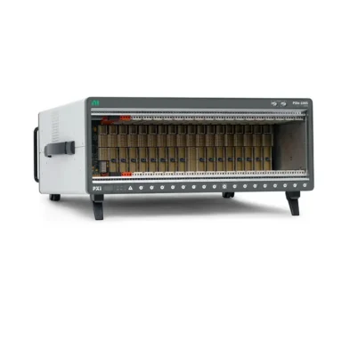
PXI timing and synchronization are the hardware and software techniques used to coordinate when multiple instruments measure, generate, switch, or communicate. These capabilities are integrated into the Шасси PXI backplane, allowing compatible modules to share clocks and trigger events without extensive front-panel cabling.
A basic automated system may only need several instruments to start from one trigger. A more demanding system may require all channels to derive their sample clocks from one reference, begin on a common clock edge, remain phase-aligned for hours, and timestamp results against GPS or another universal time source.
PXI provides several resources because these requirements are not identical. A trigger defines an event. A clock defines repeated timing intervals. A reference clock keeps device frequencies related. A time reference connects measurements to an absolute or network-wide timescale.
TriggerA hardware or software event that starts, stops, pauses, arms, or marks an operation.
Sample ClockA periodic signal that directly determines when samples are acquired or generated.
Reference ClockA stable frequency source from which instruments derive or lock their internal clocks.
Time ReferenceAn absolute or distributed timescale such as GPS, IRIG-B, PPS, or IEEE 1588.
Why Timing Matters in PXI Test Systems
Measurements from separate instruments are useful together only when their timing relationship is understood. If two digitizers sample a vibration event at slightly different instants, calculated phase, delay, position, or modal results may be incorrect. If an RF generator and analyzer do not share a stable timebase, frequency and phase relationships can drift.
Timing errors can affect automated test in several ways:
- Channels may start at different moments.
- Independent oscillators may drift during long acquisitions.
- A trigger may reach different slots at different times.
- Sample clocks may have different phases.
- Digital filters may introduce different group delays.
- Multiple chassis may not share the same absolute time.
- Software commands may have nondeterministic latency.
A well-designed timing architecture defines acceptable skew, jitter, drift, latency, and timestamp uncertainty before the hardware is selected.
Core PXI Timing Resources
PXI_CLK10: 10 MHz Reference Clock
PXI_CLK10 is the traditional PXI 10 MHz reference clock distributed through the chassis backplane. Compatible modules can phase-lock their onboard oscillators or derive internal timebases from this common reference. This reduces long-term frequency differences between devices.
The clock is available in traditional PXI and is retained in PXI Express for compatibility. Some chassis can replace or discipline the default clock from an external 10 MHz input or a timing module. The exact method depends on the chassis architecture.
Sharing PXI_CLK10 does not automatically make every sample edge simultaneous. Instruments still require compatible clock-generation circuitry and a coordinated trigger or synchronization procedure.
PXI_TRIG<0..7>: Eight-Line Trigger Bus
Земля PXI Триггерная шина provides eight shared hardware lines for intermodule triggers, clocks, and handshaking. A source module can export a start or reference trigger, and one or more destination modules can receive it.
These shared lines are flexible but are electrically loaded by multiple slots. Propagation delay and signal quality can depend on chassis topology, module position, and the number of connected devices. For the tightest synchronization, dedicated star routes are usually preferable.
PXI_STAR: Single-Ended Star Trigger
PXI Star provides dedicated, length-matched point-to-point routes between the system timing slot and peripheral slots. A compatible timing module can distribute a clock or trigger with lower slot-to-slot skew than the shared trigger bus.
PXI Star is useful when several modules must respond to the same event with more precise alignment. Availability and slot mapping depend on the chassis.
PXIe_CLK100: 100 MHz Differential Reference Clock
PXI Express adds PXIe_CLK100, a 100 MHz differential reference clock distributed independently to compatible peripheral slots. Differential signaling improves noise immunity, and the point-to-point distribution provides low slot-to-slot skew.
Compatible instruments can lock internal timing circuitry to PXIe_CLK100 and derive sample rates from a shared high-frequency reference. This is a foundation for precise multidevice synchronization in modern PXIe systems.
PXIe_SYNC100: Synchronization Clock
PXIe_SYNC100 is a 10 MHz synchronization signal related to PXIe_CLK100. It helps compatible modules coordinate the transmission and reception of synchronous events. For example, devices can send a trigger during one synchronization interval and apply it on a later common interval after every receiver has accepted it.
PXIe_DSTAR: Differential Star Connections
PXIe Differential Star provides dedicated differential point-to-point connections between the system timing slot and compatible peripheral slots. The architecture includes directional paths used for distributing and receiving high-performance clocks and triggers.
These connections offer excellent signal integrity and very low slot-to-slot skew. They are especially valuable for RF, radar, phased-array, high-speed digitizer, FPGA, and phase-coherent measurement systems.
| Resource | Тип сигнала | Main Purpose | Typical Advantage |
|---|---|---|---|
| PXI_CLK10 | 10 MHz single-ended reference | Common frequency reference | Broad PXI/PXIe compatibility |
| PXI_TRIG0–7 | Eight shared lines | Flexible triggers, clocks, handshaking | One-to-many event routing |
| PXI_STAR | Dedicated single-ended routes | Low-skew clock or trigger distribution | Better slot alignment than shared bus |
| PXIe_CLK100 | 100 MHz differential reference | High-performance frequency locking | Low skew and strong noise immunity |
| PXIe_SYNC100 | 10 MHz synchronization signal | Coordinate synchronous events | Reliable trigger alignment |
| PXIe_DSTAR | Differential point-to-point pairs | Precise trigger and clock transfer | Highest backplane synchronization performance |
Key Timing Terms Explained
Accuracy
Timing accuracy describes how closely a clock or timestamp agrees with its intended or absolute value. An oscillator can be stable over a short period but still have a consistent frequency offset.
Precision
Precision describes the repeatability of timing events. A system may repeatedly trigger two modules with the same relative delay even if both are offset from absolute time.
Skew
Skew is the difference in arrival time or effective operation time between channels, modules, or chassis. It includes backplane routing differences and internal device delays.
Jitter
Jitter is short-term variation in the timing of clock edges or events. Excessive jitter can degrade high-speed sampling, RF phase noise, and trigger repeatability.
Drift
Drift is a gradual change in frequency or phase over time, often caused by oscillator tolerance, aging, or temperature. A shared reference clock helps prevent independent devices from drifting apart.
Latency
Latency is the delay between a source event and the resulting response. Deterministic latency may be acceptable if it is known and repeatable; variable latency creates timing uncertainty.
Phase Coherence
Phase coherence means signals maintain a defined phase relationship. It requires more than starting at approximately the same time and may require shared local oscillators, reference clocks, calibration, matched paths, and device-specific synchronization procedures.
Common PXI Synchronization Methods
Software Start
The application starts each task through separate driver calls. This is simple, but operating-system and driver latency vary. Software start is suitable when timing differences of milliseconds or more are acceptable and exact correlation is not required.
Shared Hardware Trigger
One master device exports a start trigger over a backplane line, and slave devices wait for the same event. This produces a more repeatable start than independent software commands.
If the devices use independent oscillators, they can still drift after starting. Shared-trigger synchronization is best for short acquisitions or systems with moderate accuracy requirements.
Shared Sample Clock
A master device exports its sample clock directly to slave devices. Each sample is then controlled by the same periodic signal. This prevents drift and can provide close alignment if all devices support the same clock rate and routing path.
Backplane routing delay and device input delay contribute skew. This method can also be restrictive because the slaves must accept the master's clock frequency.
Reference Clock Synchronization
All devices lock their internal timing engines to a common reference such as PXI_CLK10 or PXIe_CLK100. Each instrument then derives the required sample rate locally. A synchronized hardware trigger coordinates the initial phase or start event.
This method supports devices operating at different sample rates while maintaining a stable frequency relationship. On supported PXIe instruments, reference-clock synchronization is often the most accurate and flexible method.
Time-Based Synchronization
Each device or chassis aligns its clock with a common time reference. Operations can then be scheduled for a specified time, and measurements can carry comparable timestamps. GPS, IRIG-B, PPS, IEEE 1588, and IEEE 802.1AS are examples of time references used in distributed systems.
| Method | Common Start | Prevents Drift | Different Sample Rates | Типичное использование |
|---|---|---|---|---|
| Software start | Approximate | No | Да | Noncritical sequential measurements |
| Shared trigger only | Да | No | Да | Short acquisitions and functional test |
| Shared sample clock | With trigger | Да | Usually limited | Same-rate acquisition |
| Common reference clock | With synchronized trigger | Да | Да | Accurate multidevice measurements |
| Time-based synchronization | Scheduled or triggered | Depends on discipline | Да | Multiple chassis or distributed sites |
Master-Slave Synchronization
In a master-slave architecture, one device receives or creates the asynchronous event. The master then forwards a synchronized event to the slave devices in relation to a shared timing reference. This prevents different receivers from accepting one asynchronous input on different reference-clock edges.
- Configure all channels and timing parameters.
- Select a shared reference clock for all devices.
- Designate one device as the trigger master.
- Configure slave devices to receive the master's synchronized trigger.
- Arm or start all slaves first.
- Arm the master and generate the source event.
- Verify actual channel alignment and compensate known delays if required.
Starting slave tasks before the master is important. If the master produces a short trigger before the receivers are armed, they may miss the event.
Sample Clock Timed and Oversample Clock Timed Devices
Sample Clock Timed Devices
Some devices can initiate each conversion directly from a sample-clock edge. Successive approximation ADCs are a common example. These instruments often provide flexible options for importing or exporting sample clocks and deriving clocks from internal or backplane timebases.
Oversample Clock Timed Devices
Delta-sigma converters typically operate from a continuous oversample clock and digital filters. Their output sample rate is derived from this faster internal process. Synchronization may require resetting dividers, clock generators, and converters in a coordinated sequence.
Digital filtering introduces group delay. Two modules can share a clock and trigger yet still return data associated with different effective input times if their filter delays differ. Compatible drivers may automatically compensate for supported device combinations, but the system designer should verify this behavior.
Important: A common trigger does not guarantee sample-level alignment. ADC architecture, sample-clock phase, internal pipelines, digital filters, and group delay must all be considered.
Synchronizing Modules at Different Sample Rates
Reference-clock synchronization is often the preferred approach when modules must run at different rates. Each device phase-locks to the same PXIe_CLK100 or other reference, then divides or synthesizes its own sample clock.
A synchronized start event establishes a known relationship between the generated sample clocks. The sample rates do not have to be identical, but they should have a defined mathematical relationship to the shared reference and must be supported by the device timing engines.
When comparing data, remember that samples may not occur at every common instant. Analysis software may need resampling, interpolation, or timestamp-based alignment.
Using the System Timing Slot
A PXI or PXIe system timing slot provides dedicated access to backplane clock and star-trigger resources. A compatible timing and synchronization module can:
- Generate or replace the chassis reference clock
- Route precise triggers to peripheral slots
- Receive events from modules through star connections
- Discipline an oscillator to an external reference
- Timestamp events
- Synchronize multiple chassis
- Connect the system to GPS, IRIG-B, PPS, or network time
The timing slot may also function as a normal peripheral slot in some chassis when no timing module is needed. Always confirm the specific chassis and module compatibility.
Single-Chassis Synchronization Workflow
Recommended configuration sequence:
- Define the required channel-to-channel skew and long-term drift.
- Identify the clock, trigger, and star terminals supported by every module.
- Select a common reference clock.
- Choose the master device or timing module.
- Configure sample rates and device-specific delay compensation.
- Route the synchronized start or reference trigger.
- Arm receiving devices before the source.
- Acquire test data from a known common signal.
- Measure actual skew and confirm it meets the requirement.
Synchronizing Multiple PXI Chassis
Backplane resources coordinate modules inside one chassis. Multiple chassis require external distribution of clock, trigger, or absolute time. The correct architecture depends on distance, accuracy, cabling, environmental conditions, and whether the systems must share frequency, phase, or timestamps.
Shared 10 MHz Reference Clock
One chassis or timing module can provide a 10 MHz reference to other chassis through external reference connectors. Equal-length star-distribution cables generally provide better matched delay than daisy-chaining several chassis.
A common 10 MHz reference aligns frequency, but a separate trigger or time event is normally required to coordinate operation start.
Timing Modules in Each Chassis
Installing a compatible timing module in each chassis provides more routing, clock conditioning, and event-generation options. A master timing module can distribute references and triggers to slave timing modules, which then deliver synchronized signals through their local backplanes.
GPS
GPS provides a globally available absolute time reference and can synchronize geographically separated systems. Compatible timing modules can discipline local oscillators to GPS and generate timestamped events. Antenna visibility, installation, holdover performance, and time-to-lock should be considered.
IRIG-B
IRIG-B is widely used in aerospace, defense, energy, and distributed test facilities. It distributes time-of-year information and timing markers over dedicated cabling. Accuracy depends on the format, modulation, cabling, and receiver.
Pulse Per Second
PPS provides a precise recurring edge, usually once per second. It gives a strong timing marker but may require another protocol to communicate date and time information.
IEEE 1588 Precision Time Protocol
IEEE 1588 distributes time over Ethernet. It is useful when dedicated timing cables are impractical, but network switches, topology, traffic, hardware timestamping, and profile configuration affect performance. A PTP-aware network generally provides better and more repeatable synchronization than an unmanaged network.
| Multi-Chassis Method | Primary Benefit | Typical Limitation | Best Fit |
|---|---|---|---|
| Shared 10 MHz clock | Simple frequency alignment | Needs separate event trigger | Nearby chassis |
| Timing modules and cables | Precise clock and trigger control | Additional hardware and cabling | High-accuracy laboratory systems |
| GPS | Absolute time over long distance | Antenna access and lock requirements | Distributed outdoor or remote systems |
| IRIG-B | Established absolute-time distribution | Dedicated infrastructure | Aerospace, defense, power systems |
| PPS | Precise periodic marker | May not carry full time information | Clock alignment with separate time data |
| IEEE 1588 | Time over Ethernet networks | Network-dependent uncertainty | Flexible distributed installations |
Trigger-Based vs. Time-Based Synchronization
Trigger-based synchronization distributes an event through physical signal paths. It is direct and can provide very low latency inside a chassis. However, cable and route delays become important across larger systems.
Time-based synchronization gives each device access to a common timescale. Devices can schedule events for a specific future time and timestamp asynchronous events. This is powerful for distributed systems, but synchronization quality depends on how accurately each local clock is disciplined.
Many advanced systems use both methods: a time reference maintains alignment across chassis, while local backplane triggers coordinate high-speed operations within each chassis.
NI-DAQmx and Driver-Based Synchronization
Supported NI-DAQmx devices can use multidevice tasks, reference clocks, exported triggers, and terminal routing. On compatible device combinations, the driver may automatically select synchronization resources and apply trigger-skew or group-delay correction.
Other PXI instruments use product-specific drivers. A vector signal transceiver, oscilloscope, switch, source measure unit, and DAQ device may expose different timing terminals and programming procedures. Hardware compatibility does not guarantee a common driver-level synchronization workflow.
Before programming, confirm that the chassis and slot assignments are correctly identified in NI Measurement & Automation Explorer. Accurate topology information helps the software locate valid backplane routes.
Common Timing and Synchronization Problems
Devices Start Together but Drift Apart
The instruments share a trigger but use independent oscillators. Lock them to a common reference clock or share a supported sample clock.
One Device Misses the Trigger
The receiver may not have been armed before the source generated the event. Start slave tasks first, verify edge polarity, and confirm the route.
Unexpected Constant Time Offset
Backplane propagation, cable length, module input delay, ADC pipeline, and digital-filter group delay can create a fixed offset. Measure the offset and use supported compensation or calibration.
Timing Changes Between Runs
Software start, asynchronous trigger recognition, unlocked clocks, or unstable time-reference quality may cause variable results. Use synchronous hardware methods and wait for clock discipline to stabilize.
No Valid Clock or Trigger Route
The source and destination terminals may not be internally connected, the chassis topology may be incorrect, or modules may be on different trigger segments. Review the device routing tables and chassis block diagram.
Multiple Chassis Have Increasing Phase Offset
Daisy-chained clock distribution adds cable and device delays. Use matched star distribution, calibrate fixed offsets, or install appropriate timing modules.
| Symptom | Likely Cause | Recommended Action |
|---|---|---|
| Long-term drift | Independent reference clocks | Lock devices to a common reference |
| Missed start event | Receiver not armed | Start slaves before the master |
| Fixed channel offset | Routing or group delay | Measure and compensate the known delay |
| Variable run-to-run skew | Asynchronous or software timing | Use synchronous hardware triggering |
| Route unavailable | Unsupported terminal or topology | Check module manual and chassis configuration |
| Poor network time quality | Switch or traffic uncertainty | Use PTP-aware hardware and monitor lock quality |
How to Select a PXI Synchronization Architecture
Define the Measurement Requirement
State the maximum acceptable channel skew, phase error, jitter, long-term drift, and timestamp uncertainty. Avoid vague requirements such as “all modules must be synchronized.”
Classify the System
Determine whether synchronization is needed within one module, between modules in one chassis, across multiple chassis, or across geographically separated locations.
Identify Device Timing Capabilities
List the reference-clock, sample-clock, trigger, star, and time-based terminals supported by every module. Confirm driver and operating-system support.
Choose the Clock Architecture
Select shared sample clock, PXI_CLK10, PXIe_CLK100, external reference, or disciplined timing modules based on the required rates and accuracy.
Choose the Event Architecture
Select shared trigger bus, PXI Star, PXIe DSTAR, external cabling, or time-scheduled events based on acceptable skew and system distribution.
Plan Calibration and Verification
Use a known common input or loopback signal to measure real end-to-end alignment. Include cable, analog path, ADC, digital filter, and software timestamp effects.
Best Practices for PXI Timing Systems
- Use hardware timing instead of sequential software commands for correlated measurements.
- Separate the concepts of start alignment, frequency locking, phase alignment, and absolute time.
- Arm receiver devices before enabling the trigger source.
- Use PXIe_CLK100 and differential star resources when supported and required.
- Avoid using a shared trigger bus as a high-quality clock when a dedicated clock route exists.
- Account for ADC architecture and digital-filter group delay.
- Use matched cables for external clock and trigger distribution.
- Wait for GPS, PTP, or other disciplined clocks to reach acceptable quality.
- Measure actual synchronization performance under realistic operating conditions.
- Document clock sources, trigger-line allocations, cable delays, and calibration values.
Frequently Asked Questions About PXI Timing and Synchronization
What is the difference between a clock and a trigger?
A clock is a periodic signal used to control or derive timing intervals. A trigger is an event that starts, stops, pauses, or marks an operation.
Does sharing a trigger prevent devices from drifting?
No. A shared trigger aligns the initial event, but independent oscillators can drift. Use a common reference or sample clock to maintain frequency alignment.
What is PXI_CLK10?
PXI_CLK10 is the 10 MHz backplane reference clock provided by traditional PXI and retained in PXI Express.
What is PXIe_CLK100?
PXIe_CLK100 is a 100 MHz differential reference clock distributed through compatible PXIe backplanes with low slot-to-slot skew.
What is the difference between PXI Star and PXIe DSTAR?
PXI Star uses dedicated single-ended connections. PXIe DSTAR uses dedicated differential connections and provides improved signal integrity and synchronization performance.
Can PXI and PXIe modules be synchronized together?
Often yes, if the modules share compatible reference clocks and trigger resources. Performance may be limited by the resources supported by the older device.
Can modules running at different sample rates be synchronized?
Yes, supported modules can derive different rates from a common reference and use a coordinated trigger. Their sample instants may not all coincide, so analysis must account for the rate relationship.
Do I need a timing module?
Not always. Many single-chassis systems can use built-in backplane clocks and triggers. A timing module is useful for lower skew, external references, absolute time, event timestamping, or multiple chassis.
What is the best method for multiple chassis?
There is no universal method. Nearby chassis may share a reference clock and trigger. Distributed systems may require timing modules, GPS, IRIG-B, PPS, or IEEE 1588.
How can synchronization accuracy be verified?
Apply a common known signal to the participating channels, acquire simultaneously, and calculate the measured time or phase offset. Repeat under realistic temperature, rate, and duration conditions.
Заключение
PXI timing and synchronization combine reference clocks, hardware triggers, star connections, timing modules, and software configuration to coordinate modular instruments. Traditional PXI provides PXI_CLK10, an eight-line trigger bus, and PXI Star. PXI Express adds PXIe_CLK100, PXIe_SYNC100, and differential star connections for higher-performance synchronization.
The correct method depends on the actual engineering requirement. A shared trigger may be sufficient for a short functional test. A long multichannel acquisition usually needs a common reference. Phase-coherent RF or radar testing may require differential star routing and calibration. Multiple chassis may need external clock distribution or absolute-time technologies such as GPS, IRIG-B, PPS, or IEEE 1588.
Successful synchronization requires evaluating the complete signal chain, including chassis resources, module timing engines, ADC architecture, group delay, cable delay, driver support, and application configuration. The final system should always be verified with measured timing data.
Categories
Latest Articles
Products on Sale


Need Help Choosing a Product?
Contact our sales team for product selection, pricing, availability and lead-time information.
sales@pxisource.com