






Quick Answer: Choose a PXI chassis after selecting the controller and instrument modules. Verify whether the system needs PXI, PXIe, or hybrid-compatible slots; count the usable peripheral positions and module widths; calculate data throughput, power, and cooling; and check timing resources, controller compatibility, rack dimensions, noise, and environmental limits. The best chassis is not simply the one with the most slots—it is the chassis whose backplane, slot map, bandwidth, power, cooling, and synchronization resources match the complete test system.
What Is a PXI Chassis?
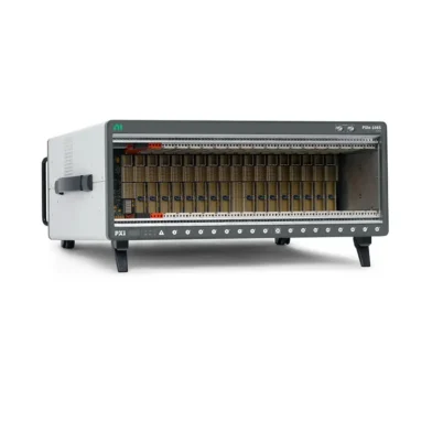
A Шасси PXI is the mechanical and electrical foundation of a PXI system. It houses the controller and instrument modules, distributes power, removes heat, carries PCI or PCI Express data, and provides shared clocks and trigger connections.
The chassis is not an empty frame. Its backplane architecture determines which modules can be installed, how data travels to the controller, which slots share bandwidth, which timing signals reach each module, and how the platform can expand.
A suitable chassis should support the current module list and provide reasonable headroom for future additions. Oversizing without analyzing compatibility can add cost and rack space without improving performance.
Choose the Modules Before the Chassis
Start with the measurement, generation, switching, timing, and interface modules. For every module, record:
- PXI, PXIe, or hybrid-compatible bus type
- Number of occupied slot widths
- Required PCI Express generation and lane width
- Expected sustained data rate
- Maximum power consumption
- Required cooling capacity
- Timing-slot, star-trigger, or local-bus requirements
- Front-panel cable and connector clearance
Also record whether the system uses an embedded PXI controller or a remote-control interface. The controller format and bandwidth must match the chassis.
Selection rule: A chassis should be selected from a verified module list and slot map. Buying the chassis first can leave the system without the correct slots, bandwidth, timing resources, power, or cooling.
Step 1: Decide Between PXI and PXIe
Traditional PXI uses a parallel PCI data bus. PXI Express, or PXIe, uses point-to-point PCI Express links and switches. PXIe offers much higher data throughput and adds advanced differential timing resources.
| Requirement | Traditional PXI Chassis | PXIe Chassis |
|---|---|---|
| Primary bus | Parallel PCI | PCI Express |
| Typical instruments | DMM, switching, relay, serial and industrial I/O | Digitizer, RF, FPGA and high-speed DAQ |
| Data throughput | Suitable for moderate data rates | High per-slot and aggregate bandwidth |
| Timing | PXI_CLK10, trigger bus and PXI Star | Retains PXI resources and adds CLK100 and DSTAR |
| New system use | Legacy or cost-sensitive low-bandwidth systems | Preferred for performance and expansion |
For a new mixed-instrument system, a PXIe chassis with hybrid-compatible slots often provides the most flexibility. However, not every legacy PXI module is mechanically compatible with a hybrid connector.
Step 2: Understand PXI Chassis Slot Types
System Controller Slot
The system slot accepts an embedded controller or compatible remote interface. Controller expansion positions may be located to its left. These expansion positions support the physical width of the controller and are not ordinary peripheral slots.
PXI Peripheral Slot
A PXI peripheral slot provides the parallel PCI interface and traditional PXI timing resources. It is intended for compatible PXI modules.
PXIe Peripheral Slot
A PXIe peripheral slot provides PCI Express connectivity for PXIe modules. It does not normally support a traditional PXI module.
Hybrid-Compatible Slot
A hybrid slot accepts PXIe modules and compatible PXI hybrid modules. It is useful when migrating a legacy system or combining low-bandwidth PXI instruments with newer PXIe hardware.
System Timing Slot
The system timing slot provides access to PXI Star, PXIe Differential Star, reference clocks, and related timing resources. A compatible timing module can distribute precise clocks and triggers. Some chassis allow this position to operate as a normal peripheral slot when no timing module is installed.
| Slot Type | Typical Hardware | Main Check |
|---|---|---|
| System slot | Embedded controller or remote interface | Controller format, power, cooling and bus generation |
| PXI peripheral | Traditional PXI instrument | Parallel PCI and connector compatibility |
| PXIe peripheral | PXIe instrument | PCIe lane width and generation |
| Hybrid-compatible | PXIe or compatible hybrid PXI module | Legacy connector restrictions |
| System timing | Timing and synchronization module | Star mapping and clock capabilities |
Step 3: Calculate the Required Number of Slots
Count usable peripheral slots rather than the model's headline slot number. Include the controller, timing module, modules wider than one slot, and any positions blocked by front-panel cables or local-bus requirements.
Create a visual slot map with the exact module model in every position. This reveals whether:
- Every module has the correct slot type
- Wide modules have enough adjacent space
- The timing module occupies the correct slot
- High-bandwidth instruments use appropriate PXIe links
- Local-bus modules are installed next to the required partner
- Front-panel cables and connectors remain accessible
Allow some expansion, but make sure the spare positions also have enough future bandwidth, power, and cooling. One empty slot is not automatically capable of supporting any future module.
Step 4: Analyze Backplane Bandwidth
PXIe chassis specifications may list per-slot bandwidth and total system bandwidth. These values describe different limits and should not be used interchangeably.
Пропускная способность на слот
Per-slot bandwidth depends on PCI Express generation and link width. A slot may have an x1, x4, x8, or wider connection. The installed module and chassis negotiate the highest link supported by both.
Пропускная способность системы
System bandwidth describes aggregate backplane data capability. It does not mean every slot can simultaneously reach that full value.
Switch Topology
Several slots may connect to one PCIe switch and share an upstream link to the controller. Inspect the chassis block diagram and group high-throughput modules so their combined traffic does not exceed a shared branch.
Practical Throughput
Actual performance is also limited by the controller link, RAM, CPU, driver, storage, file format, and simultaneous software tasks. Calculate the expected module data rate:
Data rate = channels × samples per second × bytes per sample
Add overhead and margin, then compare the workload with every point in the data path.
Backplane analysis process:
- Calculate continuous and peak data rate for each module.
- Identify the PCIe generation and lane width of each intended slot.
- Group slots by backplane switch and upstream connection.
- Compare combined module traffic with each shared link.
- Check controller, memory and storage performance.
- Reserve bandwidth for overhead and future expansion.
Step 5: Verify Controller Compatibility
The chassis and controller must be mechanically, electrically, and functionally compatible. Check:
- PXI or PXIe system interface
- Controller width and expansion space
- PCI Express generation and lane configuration
- System-slot power and cooling
- Embedded or remote-control architecture
- Chassis identification and platform-service support
- Operating system and driver compatibility
A newer high-bandwidth controller may operate in an older PXIe chassis but be limited by the chassis link. Conversely, a high-bandwidth chassis cannot overcome a slower controller interface.
Some chassis incorporate an integrated remote-control interface and do not provide a conventional system slot for an embedded controller. Verify the architecture rather than assuming every PXIe chassis accepts an embedded controller.
Step 6: Calculate Power and Cooling
Total Chassis Power
Add the maximum power requirements of the controller and all modules. Compare the total with the chassis supply capacity and available current on each voltage rail.
Per-Slot Power
A chassis may have sufficient total power but still lack the required current or connector capacity at one slot. Check module requirements against the exact slot specification.
Per-Slot Cooling
Compare each module's heat dissipation with the chassis cooling capacity per slot. High-speed controllers, RF instruments, digitizers, FPGA devices, and power modules may require higher cooling tiers.
Ambient Temperature and Airflow
Cooling performance depends on room temperature and clear airflow. Review inlet and outlet clearances, rack ventilation, airflow direction, fan mode, dust filters, and the effect of nearby equipment.
Empty-Slot Management
Filler panels and slot blockers can reduce airflow bypass and help direct cooling through installed modules. Follow the chassis manufacturer’s configuration instructions.
Thermal warning: A system may enumerate and run at startup but become unstable during long, high-load operation if cooling is insufficient. Evaluate the worst-case controller and module workload at the maximum expected ambient temperature.
Step 7: Select Timing and Synchronization Resources
Review the PXI timing and synchronization requirement before choosing a chassis. Important resources include:
- PXI_CLK10 10 MHz reference clock
- PXIe_CLK100 100 MHz differential reference clock
- PXI_TRIG0–7 trigger lines
- PXI Star trigger routing
- PXIe Differential Star connections
- System timing slot
- External 10 MHz reference input and output
- External trigger or clock connectors
- Optional disciplined oscillator or timing upgrade
A shared trigger can align a start event but does not prevent independent clocks from drifting. Phase-coherent, long-duration, RF, and multichassis applications may require a timing module or external reference architecture.
Step 8: Check Installation and Environmental Requirements
Bench or Rack Installation
Measure chassis width, height, depth, weight, rack-unit requirement, handle clearance, cable bend radius, and service access. Include rack slides or mounting kits in the bill of materials.
Acoustic Noise
High-performance cooling fans can be loud. Acoustic performance matters in laboratories, engineering offices, teaching environments, and operator stations. Some chassis provide automatic or adjustable fan modes, subject to thermal limits.
Input Power
Verify AC voltage and frequency range, DC input options, connector, circuit protection, grounding, power consumption, and regional power cord.
Temperature, Shock, and Vibration
Compare operating and storage ratings with the installation. Field, mobile, aerospace, vehicle, or factory environments may require a rugged chassis or remote placement away from vibration and contaminants.
Обслуживание
Consider access to fans, filters, power supplies, and modules. Confirm cleaning intervals, diagnostic monitoring, spare parts, warranty, and lifecycle support for systems expected to operate for many years.
| Приложение | Recommended Chassis Priorities |
|---|---|
| Basic laboratory test | Compact size, moderate slots, low noise and sufficient hybrid compatibility |
| Production functional test | Reliability, expansion, serviceability, switching capacity and 24/7 cooling |
| Высокоскоростной сбор данных | High per-slot bandwidth, balanced switch topology, RAM and storage path |
| RF and FPGA test | Maximum bandwidth, high per-slot cooling and advanced timing |
| Portable or field system | Small size, weight, DC power, ruggedness and environmental rating |
| Multichassis system | Remote-control topology, external clocks, triggers and timing modules |
PXI Chassis Selection Checklist
- Every controller and module model number is known.
- PXI, PXIe and hybrid compatibility is verified.
- A complete slot map includes controller expansion positions and module widths.
- System timing and local-bus positions are correctly assigned.
- Per-slot links and backplane switch topology support the data workload.
- The controller link does not limit the intended chassis bandwidth.
- Total power and per-rail current are sufficient.
- Each slot provides enough power and cooling for its module.
- Thermal performance is sufficient at maximum ambient temperature.
- Required clocks, triggers, star routes, and external references are available.
- Rack dimensions, noise, voltage, grounding, and environment are acceptable.
- Spare slots also have appropriate bandwidth, power, and cooling.
- Driver, platform-service, and operating-system support are confirmed.
- Rack kits, filler panels, cables, and timing accessories are included.
Common PXI Chassis Selection Mistakes
- Buying the chassis before choosing the modules
- Counting controller expansion positions as peripheral slots
- Assuming every hybrid slot supports every legacy PXI module
- Placing high-throughput modules on shared low-bandwidth branches
- Comparing only aggregate system bandwidth
- Ignoring controller-to-chassis link performance
- Checking total power without checking per-slot and per-rail limits
- Ignoring cooling at the maximum ambient temperature
- Assuming one hardware trigger provides complete synchronization
- Forgetting chassis depth, acoustic noise, cable clearance, and rack airflow
Frequently Asked Questions
Should I choose a PXI or PXIe chassis?
Choose PXIe for new high-bandwidth, RF, FPGA, digitizer, or tightly synchronized systems. Traditional PXI can be suitable for legacy and low-bandwidth instruments.
Can PXI modules work in a PXIe chassis?
Compatible PXI modules can operate in suitable hybrid or PXI peripheral slots. They cannot operate in every PXIe-only slot, and some older PXI connectors do not fit hybrid slots.
Does an 18-slot chassis provide 18 peripheral slots?
Not necessarily. The advertised count may include the system slot or other designated positions. Review the exact slot map and controller expansion area.
Does every PXIe slot have the same bandwidth?
No. Lane width, PCIe generation, switch grouping, and upstream connections can differ. Use the chassis backplane block diagram.
How many spare slots should I allow?
Allow enough compatible positions for realistic expansion, along with spare bandwidth, power, and cooling. A physical empty slot alone is not sufficient.
Can any PXIe controller work in any PXIe chassis?
Compatibility varies with system-slot architecture, controller width, bus generation, power, cooling, and integrated remote-control designs. Check the official compatibility documentation.
Why is per-slot cooling important?
High-power modules concentrate heat in individual positions. Sufficient total airflow does not guarantee that every slot can remove the module's heat under worst-case conditions.
Do I need a system timing slot?
Not for every application. It is useful when a timing module must distribute precise clocks and star triggers, synchronize multiple chassis, or connect to an absolute time reference.
Can a chassis improve measurement accuracy?
The chassis can provide stable power, cooling, reference clocks, and trigger routing, but instrument accuracy is primarily defined by the module and calibration. Temperature and timing quality can still influence system performance.
What information is needed to recommend a chassis?
Provide the controller and module model numbers, module widths, expected data rates, power, cooling, timing requirements, preferred installation, ambient temperature, and future expansion plan.
Заключение
Choosing a PXI chassis requires a complete understanding of the controller and module configuration. Begin with a verified hardware list, then create a slot map and calculate bandwidth, power, and cooling. Confirm that each position provides the correct bus connection and timing resources.
PXIe is generally the best foundation for new high-performance systems, while traditional PXI remains useful for legacy and low-data-rate applications. Hybrid-compatible chassis can support mixed systems, but every module must be checked individually.
The final decision should also include controller performance, installation size, acoustic noise, environmental limits, external references, maintenance, lifecycle, and realistic expansion. A chassis selected through this structured process will provide a more reliable and scalable test platform.
Categories
Latest Articles
Products on Sale


Need Help Choosing a Product?
Contact our sales team for product selection, pricing, availability and lead-time information.
sales@pxisource.com