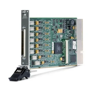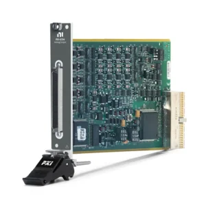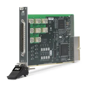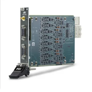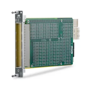




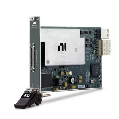
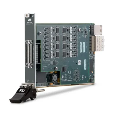
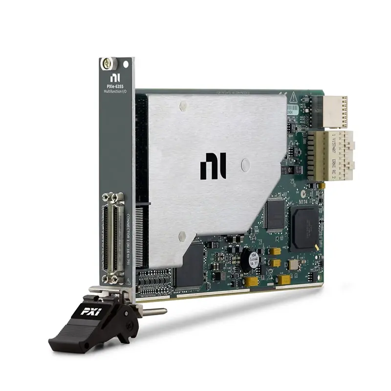
PXIe-6355 80-Channel 1.25 MS/s Multifunction I/O Module
Земля NI PXIe-6355 is an X Series PXI Express multifunction I/O module designed for high-channel-count data acquisition, automated electronic testing, process monitoring and control applications. It combines analog input, analog output, bidirectional digital I/O and counter/timer capabilities in one compact 3U PXI Express module.
The PXIe-6355 provides as many as 80 single-ended or 40 differential analog input channels with 16-bit resolution. It supports a maximum single-channel sampling rate of 1.25 MS/s and a maximum aggregate multichannel rate of 1 MS/s.
Two 16-bit analog outputs, 24 individually programmable digital I/O lines and four 32-bit counter/timers allow the module to perform measurement, stimulus, control and timing operations within the same automated system. NI-STC3 technology provides independent timing engines, advanced triggering and flexible PXI Express synchronization.
Key Features of the PXIe-6355
- 80 single-ended or 40 differential analog inputs
- 16-bit analog input resolution
- 1.25 MS/s maximum single-channel sampling rate
- 1 MS/s maximum aggregate multichannel sampling rate
- Seven programmable bipolar analog input ranges
- ±10 V maximum analog input range
- Two 16-bit analog output channels
- 2.86 MS/s maximum single-channel analog output rate
- 2 MS/s maximum two-channel analog output rate
- 24 individually programmable digital I/O lines
- Eight hardware-timed digital lines on Port 0
- 10 MHz maximum digital sample clock
- Four 32-bit general-purpose counter/timers
- Analog edge, hysteresis and window triggering
- NI-STC3 timing and synchronization technology
- Eight dedicated DMA channels
- Two 68-pin VHDCI front-panel connectors
- NI-DAQmx and LabVIEW software support
PXIe-6355 Technical Specifications
| Product Model | PXIe-6355 |
|---|---|
| Part Number | 783632-01 |
| Product Family | NI X Series multifunction data acquisition |
| Шинный интерфейс | PXI Express |
| Bus Form Factor | x1 PXI Express peripheral module |
| Compatible Slots | x1 or x4 PXI Express and PXI Express hybrid slots |
| Single-Ended Analog Inputs | 80 |
| Differential Analog Inputs | 40 |
| ADC Resolution | 16 bits |
| Sampling Architecture | Multiplexed; not simultaneous sampling |
| Maximum Single-Channel Sample Rate | 1,25 МСм/с |
| Maximum Multichannel Sample Rate | 1 MS/s aggregate |
| Minimum Sample Rate | No minimum |
| Analog Input Timing Resolution | 10 ns |
| Analog Input Timing Accuracy | 50 ppm of sample rate |
| Input Coupling | DC |
| Analog Input Ranges | ±0.1 V, ±0.2 V, ±0.5 V, ±1 V, ±2 V, ±5 V and ±10 V |
| Maximum Analog Input Working Voltage | ±11 V relative to AI GND, including signal and common-mode voltage |
| Powered Input Impedance | Greater than 10 GΩ in parallel with 100 pF |
| Input Bias Current | ±100 pA |
| Common-Mode Rejection Ratio | 100 dB typical from DC to 60 Hz |
| Small-Signal Input Bandwidth | 1.7 MHz typical, -3 dB |
| Adjacent-Channel Crosstalk | -75 dB typical at 100 kHz |
| Non-Adjacent-Channel Crosstalk | -88 dB typical at 100 kHz |
| Analog Input FIFO | 4,095 samples |
| Scan List Memory | 4,095 entries |
| Analog Input Data Transfer | Scatter-gather DMA or programmed I/O |
| Analog Triggers | 1 |
| Analog Trigger Sources | AI 0 through AI 79 or APFI 0 |
| Analog Trigger Modes | Edge, edge with hysteresis and window |
| Analog Trigger Resolution | 16 bits |
| Analog Trigger Accuracy | ±1% of range |
| Analog Output Channels | 2 |
| DAC Resolution | 16 bits |
| Maximum AO Update Rate | 2.86 MS/s for one channel; 2 MS/s for two channels |
| Analog Output Ranges | ±10 V, ±5 V or ±external reference through APFI 0 |
| Analog Output Current Drive | ±5 mA |
| Analog Output Impedance | 0.2 Ω |
| Analog Output Settling Time | 2 µs to 15 ppm for a full-scale step |
| Analog Output Slew Rate | 20 V/µs |
| Analog Output FIFO | 8,191 samples shared among active channels |
| Digital I/O Channels | 24 bidirectional channels |
| Digital Direction Control | Each terminal individually programmable as input or output |
| Hardware-Timed Digital Lines | 8 lines on Port 0 |
| Maximum Digital Sample Clock | 10 MHz |
| Digital Input FIFO | 255 samples |
| Digital Output FIFO | 2,047 samples |
| Digital Logic Level | 5 V TTL-compatible |
| Counter/Timers | 4 |
| Counter Resolution | 32 bits |
| Internal Counter Timebases | 100 MHz, 20 MHz and 100 kHz |
| External Counter Base Clock | Up to 25 MHz through PFI; up to 100 MHz through PXIe_DSTAR |
| Counter FIFO | 127 samples per counter |
| DMA Channels | 8 |
| Phase-Locked Loops | 1 |
| I/O Connectors | 2 × 68-pin VHDCI |
| Operating Temperature | 0°C to 55°C |
| Storage Temperature | -40°C to 70°C |
| Maximum Altitude | 2,000 m |
| Module Format | Standard 3U PXI Express module |
| Weight | 198 g |
| Recommended Warm-Up Time | 15 minutes |
| External Calibration Interval | 2 years |
| Software Driver | НИ-DAQmx |
The PXIe-6355 uses a multiplexed ADC. The 1.25 MS/s specification applies to single-channel acquisition, while the 1 MS/s multichannel specification is an aggregate rate shared among all channels in the scan.
PXIe-6355 Part Number and Accessories
| Item | Part Number | Описание |
|---|---|---|
| PXIe-6355 | 783632-01 | 80-channel, 16-bit, 1.25 MS/s PXI Express multifunction I/O module |
| SHC68-68 Cable | 191945-02 | 2 m twisted-pair cable with basic shielding |
| SHC68-68-EPM Cable | 192061-02 | 2 m shielded 68-pin D-Type to offset 68-pin VHDCI cable |
| TBX-68 | 777141-01 | 68-pin male SCSI connector block for field wiring |
| BNC-2090A | 779556-01 | Rack-mountable BNC accessory for 68-pin multifunction DAQ devices |
| BNC-2110 | 777643-01 | Noise-rejecting shielded BNC connector block |
| BNC-2120 | 777960-01 | Shielded BNC connector block with function-generator connections |
| SCB-68A | 782536-01 | Shielded, noise-rejecting 68-pin screw-terminal connector block |
| CB-68LPR | 777145-02 | Low-profile 68-pin I/O connector block |
| CB-68LP | 777145-01 | Low-cost unshielded 68-pin I/O connector block |
The PXIe-6355 uses two 68-pin VHDCI front-panel connectors. The required number and type of cables or connector blocks depend on which analog, digital, counter and timing terminals must be accessed.
Use shielded cables and connector blocks for noise-sensitive analog measurements. An unshielded terminal block may be suitable for prototyping or lower-frequency signals in a controlled electrical environment.
80-Channel Analog Input Architecture
The PXIe-6355 provides 80 single-ended analog input channels or 40 differential input pairs. This channel density makes the module suitable for test fixtures and monitoring systems that require many voltage measurements but do not require every channel to be sampled simultaneously.
Single-ended operation provides the highest channel count. Differential operation uses two terminals for each measurement and can provide improved rejection of common-mode interference.
16-Bit Analog Input Resolution
The onboard ADC provides 16-bit resolution with no missing codes guaranteed. A 16-bit converter divides the selected bipolar input span into 65,536 digital codes.
Measurement resolution depends on the selected input range. Using a ±100 mV range for a low-level signal provides finer nominal voltage resolution than acquiring the same signal on the ±10 V range.
1.25 MS/s Single-Channel Acquisition
The PXIe-6355 can acquire one analog input channel at up to 1.25 MS/s. This rate supports general transient capture, waveform monitoring and automated electronic test applications that require more performance than conventional low-speed data loggers.
When two or more channels are included in the scan, the maximum aggregate rate is 1 MS/s. The effective rate available to each channel depends on the total number of scanned channels and the configured scan sequence.
Multiplexed Sampling Considerations
The module switches a shared ADC among the selected analog input channels. Measurements therefore occur sequentially with a small time difference between adjacent channels.
This architecture offers high channel density and an efficient cost per channel. Applications requiring phase alignment between channels should select a simultaneous-sampling data acquisition module instead.
Seven Programmable Input Ranges
Available analog input ranges are ±0.1 V, ±0.2 V, ±0.5 V, ±1 V, ±2 V, ±5 V and ±10 V. These ranges allow the module to acquire both low-level and standard control-system voltage signals.
Choose the smallest range that safely contains the entire signal, including expected offset, noise and transient voltage. Exceeding the selected range causes clipping even when the voltage remains below the module’s absolute protection limits.
Analog Input Accuracy
Full-scale absolute accuracy depends on the selected input range, elapsed time since external calibration and temperature change since the most recent calibration. Under the assumptions defined in the official specification, full-scale accuracy is approximately 1,520 µV on the ±10 V range and 32 µV on the ±100 mV range.
System accuracy also includes sensor error, cable resistance, terminal-block characteristics, grounding and signal-source impedance. Evaluate the complete measurement chain when specifying a production or calibration system.
Input Impedance and Common-Mode Rejection
Powered analog inputs provide impedance greater than 10 GΩ in parallel with 100 pF. The module has a typical common-mode rejection ratio of 100 dB from DC through 60 Hz.
High input impedance reduces loading of many sensor and electronic signals. Proper differential wiring, shielding and grounding are still necessary to achieve stable measurements in electrically noisy environments.
Multichannel Settling Time
After the multiplexer changes channels, the analog input circuitry requires time to settle to the new voltage. Settling time depends on the selected range, voltage step and source impedance.
The ±10 V through ±1 V ranges typically settle to within four LSB for a full-scale step in 1 µs. Lower ranges may require additional time, particularly when the source has high impedance.
Analog Input Overvoltage Protection
When powered, the analog input and sense channels provide protection against ±25 V on as many as two AI pins. When unpowered, the protection level is ±15 V on as many as two pins.
These ratings protect against limited accidental overvoltage and do not represent valid measurement ranges. Normal signal and common-mode voltage must remain within ±11 V of AI GND.
Analog Edge and Window Triggering
One analog trigger can use AI 0 through AI 79 or APFI 0 as its source. The trigger supports analog edge, edge with hysteresis and analog window modes.
Trigger functions include starting an acquisition, capturing a reference trigger, pausing a task or controlling sample-clock and convert-clock operations. Hardware triggering provides more repeatable response than software polling.
Two 16-Bit Analog Outputs
The two analog output channels provide 16-bit resolution and ±5 mA output drive. One channel can update at up to 2.86 MS/s, while two-channel operation supports a maximum aggregate rate of 2 MS/s.
Output ranges include ±10 V, ±5 V and a range controlled by an external reference applied to APFI 0. Applications include programmable stimulus, voltage sweeps, actuator simulation and control-signal generation.
Regenerated Analog Waveforms
The PXIe-6355 can generate non-periodic waveforms or regenerate periodic patterns from its onboard FIFO. It can also stream regenerated data from host memory with dynamic updates.
The analog output FIFO provides 8,191 samples shared between the active channels. Select the generation mode according to waveform length, repetition requirements and real-time update behavior.
24 Bidirectional Digital I/O Lines
The module provides 24 digital terminals divided into three 8-bit groups. Every terminal can be individually configured as an input or output for static control and monitoring.
The digital lines use single-ended 5 V TTL-compatible logic. External devices must remain within the recommended input-voltage and output-current conditions.
Hardware-Timed Digital Waveforms
The eight Port 0 lines support correlated digital input and output operations at sample clock rates up to 10 MHz. This allows the module to capture digital patterns or generate timed control sequences synchronized with analog tasks.
The remaining PFI, Port 1 and Port 2 terminals support static digital I/O as well as timing input and timing output functions.
Digital Filtering and Debouncing
Port 0 inputs support digital filtering with 160 ns, 10.24 µs and 5.12 ms selections. Filtering can reject narrow glitches or contact bounce that should not be interpreted as valid state changes.
PFI inputs offer 90 ns, 5.12 µs, 2.56 ms and custom debounce intervals. Configure filters carefully because valid pulses shorter than the selected interval may also be rejected.
Four 32-Bit Counter/Timers
The PXIe-6355 includes four independent 32-bit counter/timers. Supported measurements include edge count, pulse, pulse width, period, semi-period and two-edge separation.
The counters support X1, X2 and X4 quadrature encoder measurements with Channel Z reloading. Output functions include pulses, dynamically updated pulse trains, frequency division and equivalent-time sampling.
Dedicated Counter DMA
Each counter has a dedicated 127-sample FIFO and scatter-gather DMA controller. Independent data movement reduces software overhead and supports buffered counter measurements alongside analog and digital tasks.
The module provides eight DMA channels assigned to analog input, analog output, digital input, digital output and the four counter/timer subsystems.
NI-STC3 Timing Technology
NI-STC3 technology provides independent timing engines for the analog input, analog output, digital and counter subsystems. Different tasks can operate with separate rates, clocks and triggers.
Its 100 MHz internal timebase provides 10 ns timing resolution. Retriggerable operations allow a finite acquisition or output sequence to be repeated whenever another valid trigger is received.
PXI Express Synchronization
The PXIe-6355 can receive timing and trigger signals through PFI, PXI_TRIG, PXI_STAR and PXIe_DSTAR resources. Signals can also be routed from the module to supported PXI trigger and DSTAR destinations.
The onboard phase-locked loop can synchronize the 100 MHz timebase with compatible chassis or external reference clocks. This supports coordinated operation with digitizers, waveform generators, switches and other PXI instruments.
NI-DAQmx Software Integration
NI-DAQmx provides device detection, channel configuration, timing, triggering, routing, calibration and streaming functions for the PXIe-6355.
The driver supports LabVIEW and compatible text-based environments. NI Measurement & Automation Explorer can be used to identify the module, run self-tests, perform self-calibration and access interactive test panels.
PXIe-6355 Applications
- High-channel-count voltage acquisition
- Automated electronic testing
- Production functional testing
- Design verification and validation
- Process monitoring and data logging
- Electromechanical system testing
- Encoder and position measurements
- Motor speed and frequency monitoring
- Hardware-in-the-loop test support
- Digital event capture
- Analog stimulus generation
- Laboratory automation
High-Channel-Count Data Acquisition
The PXIe-6355 can consolidate as many as 80 single-ended voltage measurements into one PXI Express slot. This makes it useful for test fixtures, electronic assemblies and industrial systems containing many test points.
Production Functional Testing
Analog inputs can measure DUT voltages while digital lines control fixture states and counters monitor frequency or pulse signals. Analog outputs can provide programmable stimulus during the same automated test sequence.
Design Verification Testing
The module can capture power-up behavior, voltage transitions and subsystem responses during engineering validation. Hardware triggering enables measurements to begin at a defined electrical or digital event.
Process Monitoring and Data Logging
Multiple voltage channels can monitor sensors, transmitters and machine signals. Long-duration acquisition can be implemented using NI-DAQmx with custom applications or compatible data-logging software.
Encoder and Motor Testing
The four counters can measure quadrature encoders, tachometers, frequency outputs and pulse trains. Analog inputs can simultaneously monitor current-sensor outputs, command voltages and other related signals.
Stimulus and Response Testing
The analog outputs can generate controlled voltage stimulus while the input channels acquire the resulting DUT response. Digital lines and counters provide additional control, status and timing functions.
Laboratory Automation
A single PXIe-6355 can replace several basic bench functions in an automated experiment. PXI Express synchronization allows it to work with switch modules, digital multimeters, programmable power supplies and other modular instruments.
PXIe-6355 Installation Workflow
Step 1: Confirm PXI Express Chassis Compatibility
Select an x1 or x4 PXI Express peripheral slot or a compatible PXI Express hybrid slot. Confirm available cooling, controller compatibility and backplane timing resources.
Step 2: Install NI-DAQmx
Install a supported NI-DAQmx version before installing or configuring the module. Confirm operating-system and development-environment compatibility.
Step 3: Power Down the Chassis
Switch off and disconnect the PXI Express chassis according to its installation procedure. Use appropriate electrostatic-discharge precautions when handling the module.
Step 4: Insert the PXIe-6355
Slide the module into the selected slot and engage it fully with the backplane connector. Secure the front-panel retaining screws.
Step 5: Choose Connection Accessories
Select SHC68-68 or SHC68-68-EPM cables and the required SCB, BNC or CB terminal accessories. Verify that the accessory provides access to the required connector and signal group.
Step 6: Wire Analog and Digital Signals
Follow the official pinout and select the appropriate differential or single-ended terminal configuration. Maintain separation between low-level analog, high-current and fast-switching digital wiring.
Step 7: Detect the Module in NI MAX
Power on the chassis and open NI Measurement & Automation Explorer. Confirm that the PXIe-6355 appears under the correct chassis, then run a self-test.
Step 8: Warm Up and Self-Calibrate
Allow at least 15 minutes of warm-up time. Run self-calibration at a stable operating temperature before making precision measurements.
Step 9: Test the I/O
Use NI MAX test panels to check analog input, analog output, digital lines and counters. Correct wiring or configuration problems before running the complete automation software.
Step 10: Configure NI-DAQmx Tasks
Define channels, ranges, terminal configurations, sample clocks, triggers and buffers. Validate the application with the intended channel count, signal frequency and acquisition duration.
PXIe-6355 Troubleshooting
The PXIe-6355 Is Not Detected
Verify that the module is fully installed in a compatible PXI Express slot. Check chassis power, controller communication and NI-DAQmx installation, then rescan the system in NI MAX.
Analog Input Measurements Are Noisy
Check grounding, shielding and terminal configuration. Use differential connections for floating or noise-sensitive signals and keep analog wiring separated from switching power circuits.
The Input Voltage Is Incorrect
Verify the selected input range and single-ended or differential configuration. Confirm that the signal and common-mode voltage remain within ±11 V of AI GND.
Multichannel Acquisition Is Slower Than Expected
The 1.25 MS/s maximum applies to one channel. When multiple channels are scanned, the maximum aggregate rate is 1 MS/s and is shared among the selected channels.
Adjacent Channels Affect Each Other
Multiplexer settling errors can occur when switching between large voltage differences or high-impedance sources. Reduce source impedance, increase settling time or reorganize the scan order.
The Analog Output Cannot Drive the Load
Each output provides a maximum current drive of ±5 mA. Use an external buffer or amplifier if the load requires more current or has a lower impedance than the module can support.
Hardware-Timed Digital I/O Is Unavailable
Hardware-timed digital waveform operations use the eight Port 0 lines. Port 1 and Port 2 support static digital I/O and PFI timing functions.
The Counter Misses Pulses
Check the input voltage, pulse width, grounding and selected debounce filter. Disable the filter or select a shorter interval when valid pulses are being rejected.
An Analog Trigger Does Not Respond
Check the trigger source, threshold, slope, window and hysteresis. Confirm that the selected signal crosses the programmed trigger condition.
Measurements Drift with Temperature
Allow the module to warm up and perform self-calibration at the operating temperature. Confirm that the external calibration remains within the recommended two-year interval.
PXIe-6355 Comparison
| Модель | Analog Input Configuration | Maximum Single-Channel Rate | Best Suited For |
|---|---|---|---|
| PXIe-6345 | 80 single-ended or 40 differential inputs | Lower than PXIe-6355 | High channel density with moderate acquisition speed |
| PXIe-6355 | 80 single-ended or 40 differential inputs | 1,25 МСм/с | Balanced high-channel-count multifunction acquisition |
| PXIe-6365 | 144 single-ended or 72 differential inputs | 2 MS/s | More analog channels and faster single-channel acquisition |
| PXIe-6383 | Simultaneous-sampling architecture | Model-specific per-channel rate | Phase-aligned multichannel measurements |
PXIe-6355 vs PXIe-6345
Земля PXIe-6345 and PXIe-6355 provide similar high-channel-count multifunction I/O architecture. The PXIe-6355 offers faster analog input acquisition and is preferable when waveform or transient performance is more important.
Select the PXIe-6345 when a lower acquisition rate is sufficient. Select the PXIe-6355 when the system requires up to 1.25 MS/s on one analog input channel.
PXIe-6355 vs PXIe-6365
Земля PXIe-6365 provides 144 single-ended or 72 differential analog inputs and a 2 MS/s single-channel rate. The PXIe-6355 provides 80 single-ended or 40 differential inputs with a 1.25 MS/s single-channel rate.
Both include two analog outputs, 24 digital I/O lines and four 32-bit counter/timers. Choose the PXIe-6355 when 80 channels provide sufficient capacity; choose the PXIe-6365 for additional channel density and acquisition speed.
PXIe-6355 vs PXIe-6383
The PXIe-6355 uses multiplexed analog inputs, while the PXIe-6383 uses a simultaneous-sampling architecture.
The PXIe-6355 is appropriate when channel density and flexible multifunction operation are priorities. A simultaneous-sampling module is preferred when channel-to-channel phase relationships must be preserved.
Selecting the Right PXI DAQ Module
Compare the required channel count, single-channel speed, aggregate scan rate, input range, simultaneous-sampling requirement, output channels and digital timing capabilities. Cable and terminal accessory requirements should also be included in the selection process.
Why Choose the PXIe-6355?
- Provides as many as 80 analog input channels
- Supports 1.25 MS/s single-channel sampling
- Offers seven programmable bipolar input ranges
- Combines analog input and output in one module
- Includes 24 individually configurable digital lines
- Provides four advanced 32-bit counter/timers
- Supports hardware analog and digital triggering
- Includes eight independent DMA channels
- Supports PXI Express clock and trigger routing
- Integrates with NI-DAQmx and LabVIEW
PXIe-6355 Frequently Asked Questions
What is the PXIe-6355?
The PXIe-6355 is an X Series PXI Express multifunction I/O module that combines analog input, analog output, digital I/O and counter/timer functions.
What is the PXIe-6355 part number?
The standard NI orderable part number is 783632-01.
How many analog inputs does it provide?
The module provides 80 single-ended analog input channels or 40 differential input pairs.
What is the maximum sampling rate?
The maximum rate is 1.25 MS/s for one active channel and 1 MS/s aggregate for multichannel acquisition.
Does the PXIe-6355 provide simultaneous sampling?
No. It uses multiplexed input architecture, so selected analog channels are sampled sequentially through a shared ADC.
What analog input ranges are supported?
Available ranges are ±0.1 V, ±0.2 V, ±0.5 V, ±1 V, ±2 V, ±5 V and ±10 V.
How many analog outputs does it have?
It provides two 16-bit analog outputs. One channel can update at up to 2.86 MS/s, while two-channel operation supports up to 2 MS/s aggregate.
How many digital I/O lines are included?
The module includes 24 individually programmable digital I/O terminals. The eight Port 0 lines support hardware-timed waveform operations.
How many counters does the PXIe-6355 provide?
It provides four 32-bit counters for event counting, frequency, period, pulse-width, encoder and pulse-generation applications.
Which connectors does the PXIe-6355 use?
The module uses two 68-pin VHDCI front-panel connectors and supports compatible SHC68-series cables and selected SCB, BNC, TBX and CB accessories.
Does the module support analog triggering?
Yes. It provides one analog trigger with edge, hysteresis and window modes using an analog input channel or APFI 0.
Which software controls the PXIe-6355?
The PXIe-6355 uses NI-DAQmx and can be programmed through LabVIEW and other supported development environments.
What is the recommended calibration interval?
The recommended external calibration interval is two years. Allow at least 15 minutes of warm-up before self-calibration or precision measurements.
Recommended Related Products
- PXIe-6345 Multifunction I/O Module
- PXIe-6351 X Series Multifunction I/O Module
- PXIe-6353 X Series Multifunction I/O Module
- PXIe-6357 X Series Multifunction I/O Module
- PXIe-6365 144-Channel Multifunction I/O Module
- PXIe-6383 Simultaneous Multifunction I/O Module
- PXIe-1092 PXI Express Chassis
- PXIe-1095 PXI Express Chassis
- View More NI PXI and PXI Express Modules
Request a Quote for the PXIe-6355
Contact us for current availability, lead time and project pricing for the NI PXIe-6355 80-Channel Multifunction I/O Module. We can also help identify compatible PXI Express chassis, SHC68 cables, terminal blocks and related NI X Series data acquisition modules for your test system.