






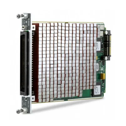
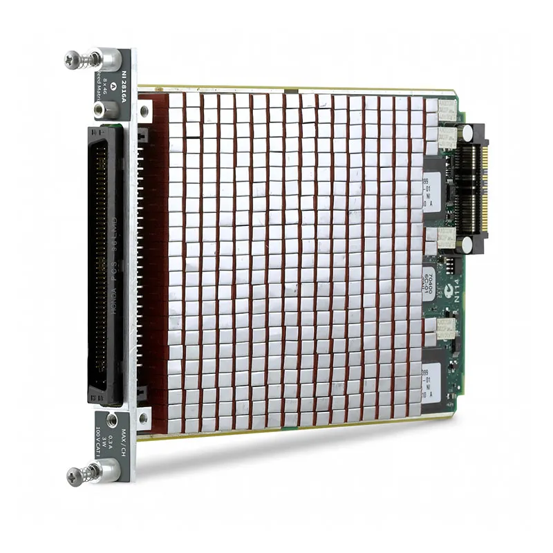
SWB-2816 8 × 46 Reed Matrix for NI SwitchBlock
The NI SWB-2816 is a 1-wire, 8 × 46 reed relay matrix card for NI SwitchBlock systems. It provides 368 crosspoints for routing shared instruments, sources, and DUT nodes under software control. The 8-row topology is suitable for automated test systems that need more common signal paths than a 4-row matrix while retaining high column density.
The module supports 100 V CAT I switching, 0.25 A switching current, 0.3 A carry current, and 3 W switching power per channel. It is intended for high-density, low-power signal routing and requires an NI PXI-2800 SwitchBlock carrier for operation in a PXI chassis.
Key Features of the SWB-2816
- 1-wire 8 × 46 reed relay matrix with 368 crosspoints
- 0.25 A maximum switching current per channel
- 0.3 A maximum carry current per channel
- 100 V CAT I row/column-to-ground rating
- 3 W maximum switching power per channel and per crosspoint
- Initial DC path resistance below 1 Ω
- Typical bandwidth of at least 8 MHz at -3 dB with 50 Ω termination
- Typical thermal EMF below 50 μV
- Eight analog-bus connections for SwitchBlock expansion
- Compatible with the NI PXI-2800 carrier and TBX-2809 terminal accessory
SWB-2816 Technical Specifications
| Параметр | Спецификация |
|---|---|
| Topology | 1-wire 8 × 46 matrix |
| Crosspoints | 368 |
| Тип реле | Non-latching reed relay |
| Relay Contact Material | Ruthenium |
| Maximum Switching Voltage | 100 VDC / 70 VAC row-to-column; 100 V CAT I row/column-to-ground |
| Maximum Switching Current | 0.25 A per channel |
| Maximum Carry Current | 0.3 A per channel |
| Maximum Switching Power | 3 W per channel; 3 W per crosspoint |
| DC Path Resistance | Initial <1 Ω; end-of-life ≥2 Ω |
| Open-Channel Resistance | >1 × 10⁹ Ω |
| Thermal EMF, Typical | <50 μV |
| Bandwidth, Typical | ≥8 MHz at -3 dB, 50 Ω termination |
| Analog Bus | Eight lines: AB<0..7> |
| Simultaneous Drive Limit | 61 relays, subject to overall carrier limits |
| Relay Operation / Release Time, Typical | Up to 8 relays: <1 ms; up to 50 relays: <2 ms |
| Power Consumption | 63 mW per energized relay |
| Power Dissipation Limit | 3.9 W per card and carrier |
| Operating Temperature | от 0 °C до 55 °C |
| Dimensions | 11.2 cm × 1.2 cm × 17.1 cm |
| Weight | 320 g |
The 8 MHz bandwidth figure is a typical specification measured with 50 Ω termination. Confirm cable length, source impedance, load impedance, and fixture capacitance when routing higher-frequency signals.
SWB-2816 Part Number and Accessories
| Item | Part Number | Selection Note |
|---|---|---|
| NI 2816A / SWB-2816 Type A | 781420-16 | Provides row and column access; one Type A card is used per SwitchBlock system. |
| NI 2816B / SWB-2816 Type B | 781421-16 | Expansion card for larger SwitchBlock matrix configurations. |
| NI PXI-2800 | Configuration dependent | Required SwitchBlock carrier for installation in a PXI chassis. |
| SH96F-96M-NI SwitchBlock Cable | 150275-01 | Compatible standard cable; available in 0.5 m, 1 m, and 1.5 m lengths. |
| SH96F-96M-RES Cable | 150579-01 | Compatible cable with 100 Ω series resistance for applicable protection requirements. |
| NI TBX-2809 | 781420-09 | Compatible unshielded screw-terminal accessory. |
SWB-2816 Matrix Architecture and Integration
8 × 46 Routing Topology
The SWB-2816 provides eight rows and 46 columns. The rows can be assigned to shared measurement instruments, sources, or fixture paths, while the columns connect to DUT nodes. This makes the module suitable when the test system needs more independent instrument paths than a 4-row matrix can provide.
The 8 × 46 topology should be selected from the routing architecture, not only the crosspoint total. Choose the SWB-2816 when eight shared paths and 46 DUT nodes are required within the same low-power matrix system.
Type A and Type B Card Selection
The NI 2816A and NI 2816B share the same electrical topology and specifications. The Type A version provides row and column access to the SwitchBlock analog bus, while the Type B version is used for expansion. A complete SwitchBlock system uses only one Type A module.
Relay Drive and Load Budget
Each energized SWB-2816 relay consumes 63 mW. NI specifies a simultaneous drive limit of 61 relays and a 3.9 W power-dissipation limit for the card and carrier. Review the relay-drive demand across the full carrier before operating a high-density switching sequence.
The 368 available crosspoints define the possible routing paths; they do not permit every relay to be closed simultaneously. Open routes that are no longer required before changing to the next connection whenever the test sequence allows it.
Relay Life and Load Protection
Relay life is determined by switched voltage, current, cable capacitance, DUT capacitance, and protection design. NI specifies electrical life up to 1 × 10⁹ operations at 5 V and 10 mA, 4 × 10⁶ operations at 10 V and 100 mA, and 5 × 10⁵ operations at 100 V and 10 mA with a resistive load below 10 pF.
Capacitive loads can create inrush current, while inductive loads can generate flyback voltage. Both effects can shorten reed-relay life. Evaluate the complete DUT, cable, and instrument path, then apply appropriate suppression or series resistance where required.
Safety Boundary
The SWB-2816 is rated for Measurement Category I only. It must not be connected to mains circuits or used for Category II, III, or IV measurements. In mixed-card or bridged SwitchBlock systems, the lowest applicable voltage rating governs the connected system.
SWB-2816 Applications
Multi-Instrument Functional Test
The SWB-2816 is suitable for automated functional test fixtures that require several shared DMM, source, or stimulus paths across multiple DUT nodes. Its eight-row topology supports more common instrument paths than the 4-row SWB-2815.
Electronic Assembly and PCB Validation
Engineers can route compatible low-power measurement and stimulus paths to selected board nodes, connectors, or fixture channels. Confirm the switched load and total fixture capacitance before using the matrix for repetitive production or validation testing.
Scalable SwitchBlock Systems
Multiple SWB-2816 cards can be combined in a PXI-2800 carrier or expanded between carriers when additional routing capacity is required. The system should be planned around row count, column count, carrier power budget, and external wiring requirements.
SWB-2816 Comparison
SWB-2816 vs SWB-2815
Земля NI SWB-2815 provides a 4 × 86 topology, while SWB-2816 provides 8 × 46. Both are 100 V, low-current, high-density reed matrices. Choose SWB-2815 for maximum column density; choose SWB-2816 when the routing plan requires more shared instrument paths.
SWB-2816 vs SWB-2817
Земля NI SWB-2817 provides a 16 × 22 topology. Select SWB-2816 when eight rows and 46 columns fit the required routing structure; select SWB-2817 when more rows are needed and fewer columns are acceptable.
SWB-2816 vs SWB-2811
Земля NI SWB-2811 provides an 8 × 21 topology with higher switching capability. Choose SWB-2816 for higher column density within the 100 V / 0.25 A class; choose SWB-2811 when the application requires 1 A switching current and 150 V capability.
Recommended Related Products
- NI PXI-2800 — required SwitchBlock carrier.
- SH96F-96M-NI SwitchBlock Cable, 150275-01 — standard compatible cable.
- SH96F-96M-RES Cable, 150579-01 — 100 Ω series-resistance cable for applicable protection requirements.
- NI TBX-2809, 781420-09 — compatible screw-terminal accessory.
Request a Quote
Contact PXISOURCE at sales@pxisource.com или WhatsApp for the NI SWB-2816. Please provide the required Type A or Type B version, quantity, carrier requirement, cable length, terminal accessory, switching voltage, current, and load type.
Часто задаваемые вопросы
Can the SWB-2816 operate directly in a PXI chassis?
No. The SWB-2816 is a SwitchBlock matrix card and requires an NI PXI-2800 carrier for operation in a PXI chassis.
What is the difference between NI 2816A and NI 2816B?
Both versions are 8 × 46 reed matrices. NI 2816A provides row and column access, while NI 2816B is used for expansion. A SwitchBlock system can use only one Type A card.
Can all 368 crosspoints be energized simultaneously?
No. NI specifies a simultaneous drive limit of 61 relays and a 3.9 W card and carrier power-dissipation limit. The complete carrier configuration must be reviewed before high-density switching.
Is the SWB-2816 suitable for 1 A switching?
No. The maximum switching current is 0.25 A per channel and the maximum carry current is 0.3 A per channel. Select a higher-power matrix, such as SWB-2811, when the application requires 1 A switching capability.
Can the SWB-2816 switch mains voltage?
No. The SWB-2816 is rated for Measurement Category I only and must not be connected to mains circuits or Category II, III, or IV signals.















