




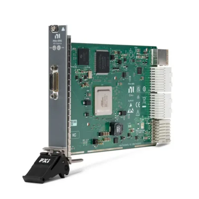

NI PXIe-1082DC 8-Slot DC-Powered PXI Express Chassis
Земля NI PXIe-1082DC is an eight-slot PXI Express chassis designed for vehicle testing, mobile measurement, aerospace validation, field data acquisition and other applications that require direct DC power operation. It accepts an input voltage from 11 VDC to 32 VDC, allowing the chassis to operate from compatible vehicle electrical systems, batteries and regulated DC power supplies.
The chassis provides one PXI Express system controller slot, four hybrid peripheral slots, two PXI Express peripheral slots and one PXI Express system timing slot. It supports up to 8 GB/s maximum system bandwidth, 315 W of total usable DC output power and up to 38.25 W of power dissipation per peripheral slot.
Integrated PXI and PXI Express timing resources include 10 MHz and 100 MHz backplane clocks, an external 10 MHz reference input and output, PXI star triggers and PXI Express differential star triggers. The standard NI part number for the PXIe-1082DC is 782946-01.
Key Features of the PXIe-1082DC
- Eight-slot 3U PXI Express chassis
- 11 VDC to 32 VDC input range
- Designed for vehicle, mobile and field-powered systems
- One PXI Express system controller slot
- Four hybrid peripheral slots
- Two dedicated PXI Express peripheral slots
- One PXI Express system timing slot
- Up to 8 GB/s maximum system bandwidth
- Up to 2 GB/s dedicated bandwidth per supported PXI Express link
- Supports compatible PXI and PXI Express modules
- 315 W maximum total usable power
- Up to 140 W power dissipation in the controller position
- Up to 38.25 W power dissipation per peripheral slot
- Two 110 CFM module-cooling fans
- Automatic and high fan-speed selection
- External 10 MHz reference input and output
- PXI and PXI Express system reference clocks
- PXI star-trigger support
- PXI Express differential star-trigger support
- Rear-panel remote power-control interface
- Operation at altitudes up to 4,600 m
DC-Powered PXI Express Architecture
The PXIe-1082DC replaces the universal AC input used by the standard PXIe-1082 with an 11 VDC to 32 VDC power input. This allows the chassis to be integrated into mobile and remote systems where regulated AC power is unavailable or undesirable.
Direct DC operation is useful in vehicle-based test systems because the chassis can be supplied by a suitable automotive electrical source or conditioned vehicle power system. It can also operate from compatible battery systems or industrial DC supplies.
The external power source must remain within the specified input range during startup, normal operation and transient conditions. Vehicle electrical systems can generate cranking voltage drops, load-dump events, reverse-polarity conditions and electrical noise, so external power conditioning may be required.
Eight-Slot Configuration
The chassis provides eight numbered positions. The first position is used by a compatible embedded controller or remote-control interface. Seven peripheral positions remain for measurement modules and timing hardware.
The peripheral section includes four hybrid slots, two dedicated PXI Express slots and one PXI Express system timing slot. This arrangement supports both high-speed PXI Express instruments and selected conventional PXI modules.
The system controller position includes three expansion locations for supported wider controllers. These expansion positions are reserved for the controller and are not independent peripheral-module slots.
Hybrid Peripheral Slots
The four hybrid peripheral slots accept compatible PXI Express modules and conventional PCI-based PXI modules with hybrid-compatible connectors. This helps engineers combine existing PXI instruments with newer PXI Express hardware.
Not every conventional PXI module can operate in a hybrid slot. Verify the connector type, driver availability, operating-system support, power requirement and chassis compatibility before installation.
PXI Express System Timing Slot
The dedicated system timing slot provides access to PXI and PXI Express clock and trigger resources. A compatible timing module can distribute an accurate reference clock, route external triggers or synchronize measurements across instruments and chassis.
The timing slot supports PXI star triggers and PXI Express differential star-trigger resources. When advanced timing is not required, the slot may accept a compatible peripheral module, subject to the device’s slot requirements.
PXIe-1082DC Technical Specifications
| Product Model | PXIe-1082DC |
|---|---|
| Part Number | 782946-01 |
| Product Type | DC-powered PXI Express chassis |
| Total Slot Count | 8 |
| System Controller Slot | 1 with three controller expansion positions |
| Hybrid Peripheral Slots | 4 |
| Dedicated PXI Express Peripheral Slots | 2 |
| PXI Express System Timing Slots | 1 |
| Maximum System Bandwidth | 8 GB/s |
| Maximum Supported PXI Express Link Bandwidth | Up to 2 GB/s per supported peripheral link |
| Power Input Type | DC |
| DC Input Voltage Range | 11 VDC to 32 VDC |
| Input Current Rating | 45 A to 15 A, depending on input voltage and load |
| Input Overcurrent Protection | 50 A circuit breaker |
| Typical Power-Supply Efficiency | 65% |
| Maximum Total Usable Power | 315 W |
| Maximum System-Slot Dissipation | 140 W |
| Maximum Peripheral-Slot Dissipation | 38.25 W |
| Module Cooling System | Two 110 CFM fans with High and Auto speed selection |
| Module Airflow Direction | Bottom of module to top of module |
| PXI Reference Clock | 10 MHz PXI_CLK10 |
| PXI_CLK10 Accuracy | ±25 ppm maximum |
| PXI_CLK10 Slot-to-Slot Skew | 500 ps maximum |
| PXI_CLK10 Jitter | 5 ps RMS maximum from 10 Hz to 1 MHz |
| PXI Express Reference Clock | 100 MHz PXIe_CLK100 and PXIe_SYNC100 |
| PXIe_CLK100 Accuracy | ±25 ppm maximum |
| PXIe_CLK100 Slot-to-Slot Skew | 100 ps maximum |
| External Reference Input | 10 MHz through rear-panel BNC |
| External Reference Input Range | 200 mVpp to 5 Vpp, sine wave or square wave |
| External Reference Input Impedance | 50 Ω ±5 Ω |
| External Reference Output | 10 MHz through rear-panel BNC |
| PXI Star-Trigger Slot-to-Slot Skew | 250 ps maximum |
| Differential Star-Trigger Slot-to-Slot Skew | 150 ps maximum |
| Differential Star-Trigger Skew | 25 ps maximum |
| Operating Temperature | 0°C to 55°C |
| Operating Humidity | 10% to 90% RH, noncondensing |
| Storage Temperature | −40°C to 71°C |
| Storage Humidity | 5% to 95% RH, noncondensing |
| Maximum Altitude | 4,600 m at 25°C ambient temperature |
| Measurement Category | CAT I |
| Dimensions | 177.1 × 271.4 × 396.5 mm |
| Weight | 8.8 kg |
| Module Format | 3U PXI and PXI Express |
11 VDC to 32 VDC Input
The wide DC input range allows the PXIe-1082DC to operate with several common vehicle, battery and industrial DC architectures. The source must provide sufficient voltage and current at the chassis terminals under all operating conditions.
Input current depends on the supply voltage and installed load. The chassis input rating ranges from approximately 45 A at the lower end of the voltage range to 15 A at the higher end. External wiring, fuses, switches and connectors must be sized for the maximum expected current.
The chassis must not be connected directly to building mains circuits or higher measurement-category sources. Its DC input is classified for Measurement Category I circuits.
315 W Total Usable Power
The PXIe-1082DC provides up to 315 W of usable DC output power to the controller and installed peripheral modules. This is lower than the 420 W available from the AC-powered PXIe-1082.
The controller position supports up to 140 W of power dissipation, while each peripheral position supports up to 38.25 W. The complete configuration must remain within total power, per-slot and voltage-rail limits.
DC Output-Rail Capacity
| Voltage Rail | Максимальный ток |
|---|---|
| +3.3 V | 32 A |
| +5 V | 19 A |
| +12 V | 32 A |
| −12 V | 1.5 A |
| +5 V Auxiliary | 2.0 A |
The outputs include short-circuit and overload protection. Certain power faults require the chassis input power to be cycled before normal operation resumes. The +3.3 V and +5 V rails also include overvoltage clamping.
DC Source and Cable Requirements
Use the DC power cable specified for the chassis and the selected power source. The cable must be rated for the maximum input current and installed so that its disconnect remains accessible.
Long cables can cause voltage drop, especially when the chassis draws substantial current at a low supply voltage. Cable gauge, connector resistance and source distance must be included in the power design.
The DC supply should include appropriate current limiting and protection. In mobile systems, additional components may be needed for reverse-polarity protection, surge suppression, filtering and controlled shutdown.
Vehicle Electrical Integration
Vehicle power is not always a stable nominal 12 V or 24 V source. Starter operation can reduce supply voltage, while inductive loads and alternator systems can produce voltage spikes and conducted noise.
Before connecting the PXIe-1082DC to a vehicle, measure the electrical environment and confirm that the voltage remains within 11 VDC to 32 VDC. Use a suitably rated DC conditioner or isolated supply when required.
8 GB/s PXI Express Backplane
The chassis supports up to 8 GB/s of aggregate system bandwidth. High-speed PCI Express links connect compatible PXI Express modules to the system controller.
This bandwidth supports high-speed data acquisition, RF measurement, FPGA processing and multichannel waveform recording. Sustainable performance also depends on the controller, storage system, module link width, drivers and simultaneous traffic.
38.25 W Per-Slot Capacity
Each peripheral slot supports a maximum power dissipation of 38.25 W. This limit applies even when the total chassis load remains below 315 W.
High-performance RF and FPGA instruments can approach or exceed this rating. Verify the individual module’s maximum power and cooling requirement before adding it to the configuration.
Forced-Air Cooling
Two 110 CFM fans create positive-pressure airflow through the module slots. Air enters through the bottom rear of the chassis and moves upward through each instrument before exhausting through the sides and top.
The separate DC power-supply cooling path draws air through the right side and exhausts through the left side. Both module and power-supply openings must remain unobstructed.
Automatic and High Fan Modes
Automatic mode adjusts fan speed according to chassis temperature and can reduce acoustic noise under light or moderate loads. High mode provides maximum airflow.
High fan mode is recommended for high-power modules, elevated ambient temperatures and rack systems with restricted ventilation. Cooling should not be reduced solely to minimize noise.
Operation at High Altitude
The PXIe-1082DC is specified for operation at altitudes up to 4,600 m at 25°C ambient temperature. This is higher than the 2,000 m rating of many AC-powered PXI chassis.
Air density decreases with altitude, reducing cooling performance. Keep ventilation paths clear and evaluate module temperature when operating near the altitude limit.
External 10 MHz Reference
The rear-panel BNC input accepts a 10 MHz reference within ±100 ppm at amplitudes from 200 mVpp to 5 Vpp. It is suitable for sine-wave or square-wave sources and has a nominal 50 Ω input impedance.
The rear-panel output provides the chassis 10 MHz reference to compatible external instruments or another chassis. Sharing the reference clock improves frequency coherence across a distributed measurement system.
Star-Trigger Resources
The system timing slot provides access to conventional PXI star triggers and PXI Express differential star triggers. These point-to-point paths support closely coordinated acquisition and generation across compatible instruments.
Trigger accuracy depends on the installed timing module, peripheral hardware, cable delays and software configuration. Precise sample alignment can require system characterization and delay compensation.
Remote Power Control
A rear-panel 9-pin D-Sub connector and power-mode switch allow an external control system to manage chassis power. This can integrate the PXIe-1082DC into a vehicle ignition sequence, remote station or automated safety system.
The external interface must follow the official pinout and electrical limits. The DC power cable remains the main method for completely disconnecting chassis input power.
PXIe-1082DC Part Number and Accessories
| Item | Part Number | Описание |
|---|---|---|
| PXIe-1082DC | 782946-01 | Eight-slot, 11 VDC to 32 VDC PXI Express chassis |
| DC Input Cable | Configuration dependent | High-current cable for connecting a compatible DC power source |
| PXI Express Embedded Controller | Model dependent | Provides local processing and system control |
| PXI Express Remote-Control Interface | Model dependent | Connects the chassis to an external computer |
| PXI Express Timing Module | Model dependent | Provides advanced reference-clock and trigger functions |
| Rack-Mount Kit | Configuration dependent | Supports front-facing or rear-facing rack installation |
| PXI Chassis Filler Panels | Configuration dependent | Covers unused slots to maintain cooling and EMC performance |
| External Reference Cable | Configuration dependent | 50 Ω BNC cable for 10 MHz reference input or output |
DC Power Cable Selection
The cable must support the maximum input current and the expected environmental conditions. Verify conductor gauge, insulation rating, connector type, polarity and mechanical retention.
A cable suitable at 32 V may not be suitable for the much higher current required near 11 V. Calculate voltage drop and heat generation at the lowest expected source voltage.
External Power Supply Selection
The supply must provide a regulated 11 VDC to 32 VDC output and enough continuous current for the complete chassis load. Startup and transient current should also be considered.
For laboratory operation, use a regulated DC supply with current limiting. Vehicle and field installations may require a dedicated DC conditioner, battery protection and transient suppression.
Embedded Controller Selection
A compatible PXI Express embedded controller can be installed in the system controller position. Controller selection should consider processor performance, memory, storage, operating system, PCI Express bandwidth and power consumption.
For battery-powered applications, controller power consumption can materially affect system runtime and thermal load.
Remote-Control Configuration
A compatible remote-control module can connect the PXIe-1082DC to an external desktop, industrial PC or server. The chassis-side interface, host-side adapter and cable must belong to a compatible remote-control family.
Remote control can keep the main computer away from vibration, temperature or electromagnetic conditions at the measurement location.
Timing Module Selection
A system timing module can add GPS, IEEE 1588, IRIG, disciplined oscillators, additional reference inputs and programmable trigger routing, depending on the selected model.
Confirm that the timing module supports the required PXI_CLK10, PXIe_CLK100 and differential star-trigger resources.
Rack-Mount and Filler-Panel Accessories
Optional rack-mount kits support front- or rear-facing installation. The rack must support the chassis weight and maintain unrestricted airflow.
Install filler panels over unused slots. They help force cooling air through occupied module positions and support electromagnetic compatibility.
PXIe-1082DC Applications
- Vehicle-based data acquisition
- Automotive road testing
- Electric-vehicle validation
- Mobile automated test systems
- Испытания в аэрокосмической и оборонной промышленности
- Avionics system validation
- Remote field measurement
- Battery-powered PXI systems
- Hardware-in-the-loop testing
- High-altitude measurement systems
- Industrial mobile laboratories
- Rail and transportation testing
- Synchronized multichannel acquisition
- Электронное проектирование верификация
Automotive Road Testing
The 11 VDC to 32 VDC input range allows the PXIe-1082DC to operate from suitably conditioned vehicle electrical systems. PXI modules can acquire temperature, strain, vibration, voltage, current, CAN, LIN and other vehicle signals.
The test-system power design must protect the chassis against cranking drops, load-dump transients, reverse connection and conducted electrical noise.
Electric-Vehicle Validation
The chassis can host data acquisition, CAN communication, FPGA and timing modules for battery-management, inverter, motor-control and thermal-system testing.
High-voltage EV signals must use properly rated isolated measurement modules and external conditioning. The chassis DC input must not be connected directly to a traction battery unless the connection satisfies its input and safety requirements.
Aerospace and Avionics Testing
The DC-powered architecture is useful in aircraft, ground vehicles and portable avionics test systems. PXI communication interfaces, digitizers and DAQ modules can be combined for subsystem validation.
The 4,600 m altitude rating supports installations beyond the operating altitude of many standard laboratory chassis. Project-specific vibration, power-conditioning and safety requirements must still be evaluated.
Mobile Data Acquisition
A compact rack or vehicle enclosure can combine the PXIe-1082DC, embedded controller, storage hardware and measurement modules into a mobile acquisition platform.
The 8 GB/s backplane supports high-speed instruments, while onboard module memory and controller storage can capture data when a continuous network connection is unavailable.
Hardware-in-the-Loop Testing
FPGA modules, analog I/O, digital I/O, communication interfaces and fault-insertion hardware can be installed for real-time controller validation.
The dedicated timing slot and differential star triggers help coordinate compatible hardware. The real-time controller and simulation model must be selected according to loop-rate and latency requirements.
Remote Field Measurement
The chassis can operate from a regulated battery or local DC power system at a remote test site. An embedded controller can perform acquisition and processing without a continuously connected external computer.
Battery capacity should be calculated from the chassis load, expected operating time, conversion efficiency, environmental temperature and reserve requirements.
Synchronized Measurement Systems
The rear-panel 10 MHz reference and system timing slot allow the PXIe-1082DC to participate in synchronized multichassis systems. A common clock improves frequency coherence across modules and chassis.
Precise trigger alignment also requires compatible trigger routing and characterization of cable and hardware delays.
PXIe-1082DC Installation Workflow
Step 1: Plan the Chassis Configuration
Identify the controller slot, four hybrid slots, two dedicated PXI Express slots and the system timing slot. Confirm the physical and electrical compatibility of every proposed module.
Step 2: Calculate Power Consumption
Add the maximum power requirements of the controller and all peripheral modules. Verify that the system remains below 315 W and within each voltage-rail and slot limit.
Step 3: Size the DC Source
Select a source capable of maintaining 11 VDC to 32 VDC at the chassis terminals. Account for cable voltage drop, startup load, ambient temperature and battery discharge.
Step 4: Design Input Protection
Provide suitable fusing, circuit protection, polarity control and transient suppression. Vehicle systems may require a dedicated automotive DC conditioner.
Step 5: Verify Cable Polarity
Confirm the positive and negative conductors before connecting the chassis. Use the specified DC cable and secure all high-current connections.
Step 6: Disconnect Input Power
Turn off and disconnect the DC source before installing the controller, timing module or peripheral instruments.
Step 7: Install the Controller
Install a compatible embedded controller or remote-control interface in the system controller position. Ensure that a wider controller uses only the designated expansion space.
Step 8: Install Timing and Peripheral Modules
Observe ESD precautions and install each instrument in a compatible slot. Do not force a conventional PXI module into a dedicated PXI Express position.
Step 9: Install Filler Panels
Cover unused slots to maintain the intended airflow and electromagnetic compatibility.
Step 10: Connect External Timing
If required, connect a compatible 10 MHz reference through a 50 Ω BNC cable. Verify the frequency, amplitude and clock-source configuration.
Step 11: Apply DC Power
Connect the DC cable and energize the external supply. Verify chassis indicators, input voltage and fan operation before starting the controller.
Step 12: Verify the System
Use NI Measurement & Automation Explorer to confirm that the controller, chassis and installed modules are detected. Run a representative test to verify timing, bandwidth and storage performance.
PXIe-1082DC Troubleshooting
The PXIe-1082DC Does Not Power On
Measure the voltage directly at the chassis input and confirm correct polarity. Verify that it remains between 11 VDC and 32 VDC under load.
Check the external fuse, cable, connector, 50 A circuit breaker and rear-panel power-control configuration.
The Chassis Starts and Then Shuts Down
The source may be reaching its current limit or the cable voltage drop may be pulling the chassis below 11 VDC. Measure the input during startup and under maximum load.
The Chassis Resets During Vehicle Starting
Starter operation can produce a voltage drop below the chassis minimum. Use an appropriate hold-up, auxiliary battery or regulated vehicle DC conditioner.
Electrical Noise Appears in Measurements
Check grounding, shielding and the quality of the external DC source. Alternators, ignition systems, inverters and DC/DC converters can introduce conducted and radiated noise.
Use isolated measurement modules or external conditioning where necessary, and keep power cables separated from low-level sensor wiring.
The Controller Does Not Boot
Power down the chassis and reseat the controller. Verify its memory, storage, power requirement and PXIe-1082DC compatibility.
A Module Is Not Detected
Refresh NI MAX, verify the driver and confirm that the module is installed in a compatible slot. Conventional PXI modules must use the hybrid peripheral positions.
The Chassis Reports an Overtemperature Condition
Check both 110 CFM fans, the bottom-rear intake, side ventilation and top exhaust. Confirm that filler panels are installed and that no module exceeds 38.25 W.
The External Clock Is Not Recognized
Verify that the source is 10 MHz within ±100 ppm and between 200 mVpp and 5 Vpp. Use a 50 Ω cable and confirm the clock selection in the timing configuration.
Modules Are Not Synchronized
Check the shared reference source, system timing module, star-trigger route and individual instrument settings. Confirm that each module supports the selected timing resource.
Continuous Acquisition Loses Data
Review aggregate data rate, controller performance, DMA buffers, host memory and storage speed. The chassis supports up to 8 GB/s, but the full system is limited by its slowest component.
Remote Power Control Does Not Work
Check the 9-pin D-Sub wiring, power-mode switch, external logic level and ground reference. Test local power control to isolate the external circuit from the chassis.
A Power Fault Does Not Recover Automatically
Some overload conditions require a full input-power cycle. Disconnect the DC source, remove the overload and wait before reconnecting power.
PXIe-1082DC Comparison
| Модель | Power Input | Maximum Usable Power | Maximum System Bandwidth | Best Suited For |
|---|---|---|---|---|
| PXIe-1082DC | 11 VDC to 32 VDC | 315 W | 8 GB/s | Vehicle, mobile, aerospace and field measurement |
| PXIe-1082 | 90 VAC to 264 VAC operating range | 420 W | 8 GB/s | Laboratory and rack-mounted AC-powered systems |
| PXIe-1086DC | DC | Configuration dependent | 12 GB/s | Large DC-powered systems requiring more slots and bandwidth |
| PXIe-1083 | AC | 293 W | 2 GB/s | Compact Thunderbolt-controlled laboratory systems |
| PXIe-1088 | AC | Configuration dependent | 8 GB/s | High-power nine-slot PXI Express systems |
PXIe-1082DC vs PXIe-1082
The two chassis share the same primary slot layout, 8 GB/s maximum bandwidth and timing architecture. Their most important difference is the input power system.
The PXIe-1082DC accepts 11 VDC to 32 VDC and provides 315 W of usable output. The PXIe-1082 uses universal AC power and provides up to 420 W.
Choose the DC model for vehicle, battery and remote installations. Choose the AC model when standard facility power and greater total module power are required.
PXIe-1082DC vs PXIe-1086DC
The PXIe-1086DC is a larger 18-slot DC-powered chassis with up to 12 GB/s system bandwidth. It is designed for applications that require more instruments than the eight-slot PXIe-1082DC can accommodate.
Choose the PXIe-1086DC for large DC-powered test systems. Choose the PXIe-1082DC when compact size, eight slots and 8 GB/s bandwidth are sufficient.
PXIe-1082DC vs PXIe-1083
The PXIe-1083 is a five-slot AC-powered chassis with integrated Thunderbolt control. It connects directly to a compatible laptop or workstation and supports up to 2 GB/s.
The PXIe-1082DC provides more slots, higher bandwidth, DC power and a system timing slot. The PXIe-1083 is better suited to compact laboratory systems with an external Thunderbolt host.
Recommended Related Products
- PXIe-1082 8-Slot AC-Powered PXI Express Chassis
- PXIe-1086DC 18-Slot DC-Powered PXI Express Chassis
- PXIe-1083 Thunderbolt PXI Express Chassis
- PXIe-1088 9-Slot PXI Express Chassis
- Встроенный контроллер PXIe-8822
- PXIe-8862 Embedded Controller
- PXIe-6674T Timing and Synchronization Module
- View More NI PXI and PXI Express Chassis
Selecting the Right DC-Powered PXI Chassis
Choose the PXIe-1082DC when the system needs direct 11 VDC to 32 VDC input, eight PXI Express slots, a system timing position and up to 8 GB/s bandwidth.
Select a larger DC chassis when more instruments or higher aggregate bandwidth are required. Choose an AC model when the system operates primarily in a laboratory and requires greater total power.
Why Choose the PXIe-1082DC?
- Operates directly from 11 VDC to 32 VDC
- Supports vehicle, battery and remote power architectures
- Provides up to 8 GB/s system bandwidth
- Includes four hybrid peripheral slots
- Includes two dedicated PXI Express slots
- Provides a dedicated system timing slot
- Supports external 10 MHz reference input and output
- Provides PXI and differential star-trigger resources
- Supports operation at altitudes up to 4,600 m
- Provides a compact platform for mobile automated testing
PXIe-1082DC Frequently Asked Questions
What is the PXIe-1082DC?
The PXIe-1082DC is an eight-slot, DC-powered PXI Express chassis designed for vehicle, mobile, aerospace and field measurement systems.
What is the PXIe-1082DC part number?
The standard NI part number is 782946-01.
What input voltage does it require?
The chassis accepts an input from 11 VDC to 32 VDC.
Can it connect directly to a vehicle battery?
It can operate from a compatible vehicle power system, but external conditioning may be required to protect against cranking drops, load-dump transients, reverse polarity and electrical noise.
What is the maximum input current?
The rated input current ranges from 45 A to 15 A depending on the supply voltage and chassis load.
How much usable power does it provide?
The PXIe-1082DC provides up to 315 W of total usable output power.
How many peripheral slots are available?
It provides four hybrid peripheral slots, two dedicated PXI Express peripheral slots and one PXI Express system timing slot.
What is the maximum system bandwidth?
The chassis supports up to 8 GB/s of aggregate system bandwidth.
Can conventional PXI modules be installed?
Yes, but only hybrid-compatible conventional PXI modules can be installed in the four hybrid slots.
Does it support an embedded controller?
Yes. A compatible PXI Express embedded controller can be installed in the system controller position.
Can it use a remote external computer?
Yes. A compatible PXI Express remote-control module can connect the chassis to an external computer.
Does it have a system timing slot?
Yes. It provides one dedicated PXI Express system timing slot.
Can the chassis use an external reference clock?
Yes. The rear-panel BNC input accepts a 10 MHz reference between 200 mVpp and 5 Vpp.
What is the maximum operating altitude?
The chassis is specified for operation up to 4,600 m at 25°C ambient temperature.
What is the difference between PXIe-1082 and PXIe-1082DC?
The PXIe-1082DC uses 11 VDC to 32 VDC input and provides 315 W, while the PXIe-1082 uses AC input and provides up to 420 W.
Does the chassis include an AC adapter?
The PXIe-1082DC is designed for direct DC input. Any external AC-to-DC supply must provide the required regulated voltage, current and protection.
Can the power supply be replaced?
Yes. The internal power-supply shuttle is designed for replacement in less than five minutes by qualified personnel after input power is disconnected.
What should be confirmed before ordering?
Confirm the 782946-01 part number, DC source voltage, maximum input current, cable and connector, protection requirements, controller, module compatibility, bandwidth, timing hardware and rack accessories.
Request a Quote for the PXIe-1082DC
Contact us for current availability, lead time and project pricing for the NI PXIe-1082DC 8-Slot DC-Powered PXI Express Chassis, part number 782946-01.
We can also help select compatible DC input cables, power-conditioning equipment, PXI Express embedded controllers, remote-control interfaces, timing modules and measurement hardware for vehicle and field test systems.















