






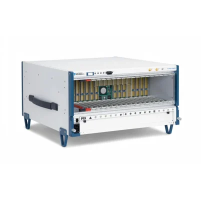
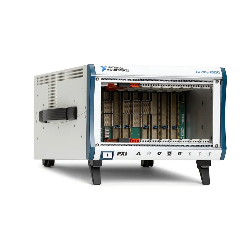
PXIe-1062Q 8-Slot PXI Express Chassis
Земля NI PXIe-1062Q is an eight-slot PXI Express chassis designed for automated test, data acquisition, RF measurement, hardware-in-the-loop validation and laboratory instrumentation systems. It combines traditional PXI peripheral slots with PXI Express hybrid slots and a dedicated PXI Express system timing slot.
The chassis provides as much as 3 GB/s maximum system bandwidth, with up to 1 GB/s of dedicated single-direction bandwidth for each supported PXI Express peripheral link. Its mixed-slot architecture allows engineers to integrate legacy PXI instruments and newer PXI Express modules in the same test platform.
The PXIe-1062Q also provides low-jitter 10 MHz and 100 MHz reference clocks, external 10 MHz clock input and output connections, remote power-inhibit control, voltage monitoring and a replaceable power-supply-and-fan shuttle. These capabilities make it suitable for synchronized and serviceable test systems operating in laboratory or production environments.
Key Features of the PXIe-1062Q
- Eight-slot 3U PXI Express chassis
- One PXI Express system controller slot
- Four conventional PXI peripheral slots
- Two PXI Express hybrid peripheral slots
- One PXI Express system timing slot
- Up to 3 GB/s maximum PXI Express system bandwidth
- Up to 1 GB/s dedicated bandwidth per PXI Express link
- 132 MB/s shared bandwidth for conventional PXI modules
- 38 W cooling capacity per slot
- 353.6 W maximum total usable power
- 0°C to 55°C operating-temperature range
- Quiet operation as low as 43.6 dBA in Auto fan mode
- 10 MHz and 100 MHz low-jitter reference clocks
- Rear-panel 10 MHz reference input and output
- PXI trigger bus, PXI star trigger and PXIe differential star triggering
- Remote power inhibit and voltage monitoring
- Replaceable AC power-supply-and-fan shuttle
- Benchtop and 19-inch rack-mount installation options
PXIe-1062Q Technical Specifications
| Product Model | PXIe-1062Q |
|---|---|
| Product Type | PXI Express chassis |
| Chassis Format | 3U, 8-slot |
| Total Slot Count | 8 slots, including the system controller slot |
| System Controller Slots | 1 PXI Express system slot |
| PXI Peripheral Slots | 4 |
| PXI Express Hybrid Slots | 2 |
| System Timing Slots | 1 PXI Express системный слот синхронизации |
| Maximum System Bandwidth | 3 GB/s |
| PXI Express Slot Bandwidth | Up to 1 GB/s dedicated, single direction |
| PXI Bus Bandwidth | 132 MB/s shared |
| PCI Express Link Width | x4 links for supported PXI Express peripheral positions |
| Power Supply | Universal AC power supply |
| Maximum Total Usable Power | 353.6 W |
| Slot Cooling Capacity | 38 W per slot |
| Fan Modes | Auto and High |
| Minimum Acoustic Emission | Approximately 43.6 dBA in Auto mode at ambient temperatures up to 30°C |
| 10 MHz Reference Clock Accuracy | ±25 ppm maximum |
| 10 MHz Reference Clock Jitter | Less than 5 ps |
| PXI_CLK10 Slot-to-Slot Skew | 250 ps maximum |
| 100 MHz Reference Clock Accuracy | ±25 ppm maximum |
| PXIe_CLK100 Slot-to-Slot Skew | 100 ps maximum |
| Differential Star Trigger Skew | Less than 150 ps between supported PXI Express slots |
| External Clocking | Rear-panel 10 MHz reference input and output |
| External Trigger Access | No integrated external PXI trigger connectors |
| Remote Control Connection | Rear-panel DB-9 power-inhibit and voltage-monitoring connector |
| Operating Temperature | 0°C to 55°C |
| Dimensions | 177.1 mm × 271.4 mm × 396.5 mm (6.97 in. × 10.68 in. × 15.61 in.) |
| Weight | Approximately 8.8 kg (19.4 lb) |
| Redundant Power Supply | No |
| Configuration Software | NI Measurement & Automation Explorer |
System bandwidth represents the maximum capability of the chassis backplane. Actual data throughput depends on the controller, module, PCI Express link, driver, software architecture and storage subsystem used in the complete system.
PXIe-1062Q Part Number and Accessories
| Item | Part Number | Описание |
|---|---|---|
| PXIe-1062Q Complete Chassis | 779633-01 | Eight-slot 3U PXI Express and PXI chassis with AC power supply and cooling assembly |
| PXIe-1062Q Backplane Only | 780595-01 | Eight-slot PXIe-1062Q backplane configuration without the complete standard chassis assembly |
| PXI 8-Slot Front Rack-Mount Kit | 778643-01 | Front rack-mount hardware for compatible eight-slot NI PXI chassis |
| PXI EMC Filler Panel | 778700-01 | Filler panel for unused chassis slots to maintain airflow and electromagnetic compatibility |
| Rear Rack-Mount Kit | Configuration dependent | Provides additional rear support when installing the chassis in a 19-inch equipment rack |
| Replacement Power-Supply-and-Fan Shuttle | Revision dependent | Service assembly containing the replaceable AC power supply and chassis cooling fans |
| PXI Express Embedded Controller | Model dependent | Installs in the system controller slot to create a self-contained PXI system |
| PXI Express Remote-Control Module | Model dependent | Connects the chassis to a compatible external computer through an MXI-Express interface |
The complete chassis and backplane-only versions have different ordering purposes. Confirm whether the application requires a complete operational chassis or only a replacement/integration backplane before purchasing.
The PXIe-1062Q is a legacy product under limited support. Accessory and replacement-part availability can vary according to hardware revision and region. Verify rack-mount, power-supply and remote-controller compatibility before ordering.
Eight-Slot Mixed-Instrument Architecture
The PXIe-1062Q was designed to support mixed generations of PXI instrumentation. Its backplane combines four conventional PXI peripheral slots, two hybrid peripheral slots and one PXI Express system timing slot.
This configuration is useful when an existing test system contains valuable PXI instruments but also requires higher-throughput PXI Express digitizers, waveform generators, RF instruments or FPGA modules.
Because the slots are not electrically identical, the physical connector must not be the only factor used to determine compatibility. The module type, backplane interface, controller support, power requirements and cooling requirements must all be checked.
PXI Express System Controller Slot
The leftmost system slot accepts a compatible PXI Express embedded controller or supported remote-control interface. The controller provides the primary PCI Express connection between the test software and the chassis backplane.
An embedded controller creates a compact, self-contained measurement system. A remote-control interface allows the PXIe-1062Q to be connected to an external desktop computer, workstation or other compatible host.
Four Conventional PXI Peripheral Slots
The four PXI slots support compatible 3U PXI and CompactPCI-based peripheral modules. These positions use the conventional 32-bit, 33 MHz PCI bus, providing up to 132 MB/s of shared theoretical bandwidth.
Typical modules installed in these slots include digital multimeters, switch modules, serial interfaces, multifunction DAQ devices and other instruments that do not require a PXI Express connection.
The 132 MB/s bandwidth is shared among devices connected to the same conventional PCI segment. Applications with several continuously streaming modules should include a complete bandwidth analysis.
Two PXI Express Hybrid Slots
The two hybrid positions provide greater module flexibility. They can accept compatible PXI Express peripheral modules as well as PXI modules designed for hybrid-slot compatibility.
When a PXI Express module is installed, the slot can provide a dedicated x4 PCI Express link with as much as 1 GB/s of single-direction theoretical bandwidth. When a hybrid-compatible PXI module is installed, it communicates through the conventional PXI bus.
Some older PXI modules use connector features that prevent installation in a hybrid slot. Check the module documentation rather than assuming that every conventional PXI module can operate in a hybrid position.
PXI Express System Timing Slot
The system timing slot provides dedicated timing resources for compatible PXI Express timing and synchronization modules. It can distribute precise clocks and triggers to other instruments through the chassis backplane.
Using a timing module in this position can improve multichannel synchronization, replace or discipline the chassis reference clocks and coordinate instruments across multiple PXI chassis.
The system timing position may also accept certain PXI Express peripheral modules when dedicated timing control is not required. Compatibility should be confirmed in the documentation for the selected module.
3 GB/s Backplane Bandwidth
The PXIe-1062Q provides three dedicated x4 PCI Express links between the system controller and supported PXI Express peripheral positions. Together, these links provide as much as 3 GB/s of theoretical single-direction system bandwidth.
This architecture is suitable for many digitizer, FPGA, RF and high-speed data-acquisition applications. It also prevents traffic on one dedicated PXI Express link from consuming the bandwidth assigned to another link.
Real application throughput is normally lower than the theoretical backplane rating because protocol overhead, controller performance, memory transfers, software processing and storage speed all affect the completed data path.
353.6 W Usable Power
The chassis provides up to 353.6 W of usable power for the controller and installed instruments. Power is distributed across the PXI and PXI Express voltage rails according to the applicable platform specifications.
A system designer should calculate both total chassis power and current consumption on each individual supply rail. A configuration can remain below the total wattage rating while exceeding the available current on one specific rail.
High-power embedded controllers, digitizers, FPGA instruments, source measure units and RF modules should be included in the power budget before the system is assembled.
38 W Per-Slot Cooling
The PXIe-1062Q supports as much as 38 W of cooling capacity per slot under the specified operating conditions. Forced air enters through the chassis intake and moves across each installed controller and peripheral module.
Empty positions should be covered with filler panels. Leaving slots open changes the chassis pressure and airflow distribution, which can reduce cooling across adjacent high-power modules.
Air intake and exhaust openings must remain unobstructed. When the chassis is installed in a rack, the surrounding equipment must not recycle hot exhaust air into the PXIe-1062Q intake.
Automatic and High Fan Modes
The chassis includes Auto and High fan settings. Auto mode adjusts fan speed according to the measured intake-air temperature, reducing acoustic noise when the full cooling capacity is not required.
At ambient temperatures up to approximately 30°C, acoustic emission can be as low as 43.6 dBA at the operator position. This makes the chassis practical for benchtop development, engineering offices and laboratories where continuous fan noise is undesirable.
High mode operates the cooling system at elevated speed regardless of the measured ambient temperature. It is recommended for high-power module configurations, elevated-temperature environments and rack installations where acoustic noise is less important than cooling margin.
10 MHz PXI Reference Clock
The backplane distributes a 10 MHz reference clock to the compatible PXI and PXI Express positions. The internal oscillator has a specified accuracy of ±25 ppm, jitter below 5 ps and maximum slot-to-slot skew of 250 ps.
Compatible measurement modules can derive their sample or timing clocks from this shared reference. Using a common timebase reduces long-term drift between instruments and simplifies synchronized stimulus-and-response measurements.
100 MHz PXI Express Reference Clock
PXI Express positions receive the differential PXIe_CLK100 and PXIe_SYNC100 reference signals. The 100 MHz reference has ±25 ppm specified accuracy and maximum slot-to-slot skew of 100 ps.
The differential architecture provides improved noise immunity and tighter synchronization for compatible PXI Express instruments. A module can also derive a synchronized 10 MHz clock from PXIe_CLK100 using PXIe_SYNC100.
PXI and PXI Express Trigger Resources
The PXIe-1062Q provides the eight-line PXI trigger bus and the single-ended PXI star trigger resources used by traditional PXI instruments. These lines support event signaling, handshaking and synchronized acquisition or generation.
Supported PXI Express positions also receive differential star trigger connections from the system timing slot. These dedicated point-to-point connections provide less than 150 ps of intermodule skew for compatible synchronization applications.
The chassis does not provide direct front- or rear-panel access to the general PXI trigger bus. Applications requiring external trigger connectors normally use an appropriate timing, synchronization or interface module.
External 10 MHz Reference Connections
Rear-panel BNC connectors provide 10 MHz reference input and output access. When the chassis detects a valid external 10 MHz input, it phase-locks PXI_CLK10, PXIe_CLK100 and PXIe_SYNC100 to the external source.
The reference output supplies a buffered copy of the chassis 10 MHz clock. It can be used as part of a multi-instrument or multi-chassis synchronization architecture, subject to the signal-level, termination and cabling requirements in the chassis manual.
Remote Power Inhibit and Monitoring
A rear-panel DB-9 connector provides remote power-inhibit control and access to chassis voltage-monitoring signals. This connection can be integrated into a test-rack safety circuit, external system controller or facility interlock.
Remote inhibit can place the chassis power supply into its inhibited state without requiring an operator to reach the front-panel power switch. It should be implemented according to the specified connector pinout and electrical interface requirements.
The monitoring connection should not be treated as a precision measurement output. Its main purpose is supervisory monitoring of the chassis power rails.
Power, Temperature and Fan Monitoring
The PXIe-1062Q monitors internal power-supply voltages, intake-air temperature and fan operation. The front-panel power-switch indicator uses different colors and states to communicate normal operation or a detected chassis condition.
Monitoring helps identify cooling or power problems before they produce unstable module operation. If the chassis reports a fault, stop the test and inspect airflow, fan operation, ambient temperature and module power consumption.
Replaceable Power-Supply-and-Fan Shuttle
The AC power supply and cooling fans are installed in a removable rear shuttle. Qualified service personnel can replace the assembly without completely disassembling the chassis.
The modular shuttle reduces repair time and allows the power and cooling subsystem to be serviced as one assembly. NI documentation describes a mean time to repair of less than five minutes for the shuttle replacement procedure.
The chassis must be powered off and disconnected from AC power before the shuttle is removed. Replacement should only be performed with the correct assembly and by personnel familiar with electrical and electrostatic-discharge safety procedures.
Benchtop and Rack-Mount Integration
Adjustable front feet allow the chassis to be tilted for easier access during benchtop development. This arrangement is useful when engineers frequently connect probes, cables and adapters to module front panels.
Front and rear rack-mount hardware is available for installation in a standard 19-inch equipment rack. Rear support is particularly important in transportable systems or installations subject to vibration and mechanical loading.
Rack installation must provide adequate clearance for intake airflow, exhaust airflow, the AC connector, clock cables, remote-inhibit wiring and module front-panel cables.
PXIe-1062Q Applications
- Automated electronic test equipment
- Production functional testing
- Mixed PXI and PXI Express instrumentation systems
- Высокоскоростной сбор данных
- RF and wireless device testing
- Oscilloscope and digitizer systems
- Симуляция с аппаратным входом
- Electronic control-unit validation
- Sound and vibration measurement
- Multichannel synchronized measurements
- Laboratory research and development
- Rack-mounted validation systems
- Legacy PXI system modernization
Automated Production Testing
The PXIe-1062Q can host switching, measurement, stimulus and communication modules in one compact platform. TestStand, LabVIEW or another automation environment can coordinate these instruments through the installed embedded or remote controller.
The combination of conventional PXI and PXI Express positions is useful for production systems that need to preserve existing switch or communication modules while adding higher-speed measurement hardware.
High-Speed Data Acquisition
PXI Express digitizers and DAQ devices can use the chassis’s dedicated PCI Express links to transfer waveform data to the system controller. This architecture supports continuous acquisition, transient capture and multichannel recording applications.
Before configuring a sustained acquisition, verify the throughput of every component between the module and final storage destination. The chassis link, controller memory, processor, software buffers and storage device must all support the required data rate.
RF and Wireless Testing
The PXIe-1062Q can combine vector signal generators, analyzers, RF downconverters, frequency sources and switching modules in an integrated RF test system.
Shared reference clocks and backplane triggers help coordinate signal generation and acquisition. External 10 MHz clocking also allows the PXI instruments to be referenced to compatible laboratory frequency standards.
Hardware-in-the-Loop Validation
Hardware-in-the-loop systems can use the chassis to integrate FPGA processing, analog I/O, digital I/O, vehicle communication interfaces and fault-insertion switches.
The mixed-slot design is particularly useful for maintaining legacy PXI communication or switching hardware while higher-throughput PXI Express modules perform real-time simulation and waveform transfer.
Измерение звука и вибрации
The relatively quiet Auto fan mode makes the PXIe-1062Q suitable for laboratory sound and vibration applications where excessive chassis noise could interfere with the working environment.
For critical acoustic measurements, the chassis should still be isolated from microphones and mechanical sensors. Fan vibration, cable movement and airflow should be considered as possible measurement influences.
Legacy PXI System Modernization
The PXIe-1062Q provides a migration path for test systems containing both older PXI modules and newer PXI Express instruments. Compatible legacy devices can remain in the conventional PXI or hybrid slots while selected functions are upgraded.
Before migrating an existing system, verify driver support on the intended operating system. Physical slot compatibility does not guarantee that an older module is supported by current software.
PXIe-1062Q Installation Workflow
Step 1: Inspect the Chassis
Remove the chassis from its packaging and inspect the enclosure, backplane connectors, air intake, fan assembly and power connector. Do not apply power if the chassis appears damaged.
Place the PXIe-1062Q on a stable surface with sufficient clearance around the intake and exhaust openings. Install rack-mount hardware before loading the chassis with instruments when rack deployment is planned.
Step 2: Connect Protective Earth
Connect the approved AC power cord to the chassis and a properly grounded outlet. The protective-earth connection should be established before modules or external signal cables are installed.
Do not use adapters that defeat the grounding conductor. Additional rack grounding should follow the electrical and safety requirements of the complete test installation.
Step 3: Plan the Slot Assignment
Prepare a slot map before installing the controller and instruments. Consider interface compatibility, required bandwidth, timing resources, module width, heat dissipation and front-panel cable clearance.
System Controller Slot
Install the embedded controller or compatible remote-control interface in the leftmost system slot. This position is reserved for the device that manages communication with the backplane.
PXI Peripheral Slots
Use the four conventional PXI positions for supported PCI-based PXI instruments. These modules share the conventional PXI bus bandwidth.
Hybrid Peripheral Slots
Use the two hybrid positions for supported PXI Express modules or PXI modules specifically designed for hybrid-slot compatibility.
System Timing Slot
Reserve the system timing position for a timing and synchronization module when the system requires advanced clock replacement, star triggering or multichassis synchronization.
Step 4: Calculate Power and Cooling Requirements
Add the maximum power consumption of the controller and every peripheral module. Confirm that the total remains within the chassis capacity and that individual supply-rail current limits are not exceeded.
Review the power dissipation of each module and make sure the required cooling does not exceed the available 38 W per slot. High-power modules should be distributed according to their installation instructions.
Step 5: Install the Controller and Modules
Turn off the chassis and disconnect signal cables before installing hardware. Handle each module using appropriate electrostatic-discharge precautions.
Align the module with the upper and lower card guides, slide it evenly into the chassis and fully engage the backplane connectors using the injector/ejector handle. Tighten the front-panel mounting screws without overtightening them.
Step 6: Install Filler Panels
Cover every unused slot with an appropriate EMC filler panel. Filler panels preserve the designed airflow path and help maintain the chassis electromagnetic-compliance performance.
Step 7: Select the Fan Mode
Select Auto mode for normal benchtop operation when acoustic noise is important and the installed hardware remains within the available cooling margin.
Select High mode for high-power configurations, elevated ambient temperature, enclosed rack installations or applications in which maximum cooling is preferred.
Step 8: Connect Clocking and Remote-Control Signals
If an external frequency reference is required, connect a compatible 10 MHz source to the rear-panel reference input. Use properly terminated coaxial cable and verify that the source meets the chassis input requirements.
Connect the remote-inhibit DB-9 interface only after verifying the pinout. Incorrect wiring can prevent normal startup or produce misleading voltage-monitoring results.
Step 9: Power On and Configure the System
Apply AC power and turn on the chassis. Confirm that the power indicator reports normal operation and that the fans begin operating.
Start the controller and open NI Measurement & Automation Explorer. Confirm that the PXIe-1062Q and installed instruments are identified in their intended slot positions.
Step 10: Verify the Completed Test System
Run self-tests for the installed instruments, verify clock-lock status where applicable and test the required backplane trigger routes.
For streaming systems, execute a representative data-transfer test. Monitor temperature, fan status and application throughput before releasing the system for unattended operation.
PXIe-1062Q Troubleshooting
Chassis Power Problems
The chassis does not power on
Verify the AC outlet, power cord and rear-panel power connection. Check whether the remote-inhibit input is preventing the power supply from starting. Disconnect unnecessary modules and try the chassis again if an overload is suspected.
The power indicator reports a fault
Stop the test and inspect the chassis fans, air filter, intake temperature and installed module power load. A voltage, temperature or fan-monitoring fault can cause the front-panel indicator to change state.
Module Detection Problems
A module is missing in NI MAX
Power off the system and confirm that the module is installed in a compatible slot and fully seated in the backplane. Check the required device driver and refresh the hardware list in NI MAX.
A PXI module does not work in a hybrid slot
Confirm that the module is hybrid-slot compatible. Some older PXI modules use connector features or local-bus resources that are not supported in a PXI Express hybrid position.
A PXI Express module does not work in a PXI slot
Move the module to one of the supported PXI Express positions. A conventional PXI slot does not provide the PCI Express links required by a PXI Express peripheral module.
Bandwidth and Performance Problems
Streaming performance is lower than expected
Check whether the module is connected through a dedicated PXI Express link or the shared conventional PXI bus. Review controller performance, DMA configuration, software buffer sizes and storage write speed.
Multiple PXI modules compete for bandwidth
Conventional PXI modules can share the same 132 MB/s PCI bus. Reduce simultaneous streaming, distribute high-throughput functions to PXI Express modules or use a chassis with a higher-performance backplane architecture.
Cooling and Acoustic Problems
The chassis fans are unusually loud
Confirm that the fan selector is in Auto mode when reduced acoustic noise is required. High intake temperature causes the fans to accelerate automatically, so inspect rack ventilation and nearby heat sources.
A module reports excessive temperature
Switch the chassis to High fan mode, clean the intake filter and install filler panels in every unused position. Make sure cables or adjacent equipment are not blocking the intake or exhaust openings.
A fan does not operate
Power off the chassis and inspect the removable power-supply-and-fan shuttle. Do not continue running high-power modules if the chassis cannot provide the required forced-air cooling.
Clock and Synchronization Problems
The external 10 MHz reference does not lock
Verify the reference frequency, amplitude, waveform, impedance and cable termination. Check that the signal reaches the correct rear-panel input rather than the buffered reference output.
Measurements drift between modules
Confirm that the instruments are using a shared chassis reference and that their sample clocks are configured correctly. A common reference removes frequency drift but does not automatically align every acquisition start event.
Trigger timing is inconsistent
Use backplane trigger or star-trigger resources instead of software timing when deterministic alignment is required. Check trigger routing, module capability and timing-slot configuration.
Remote-Control Problems
The chassis remains inhibited
Disconnect the remote-inhibit cable and test normal front-panel operation. If the chassis then starts correctly, inspect the DB-9 wiring, external relay or control circuit.
An external host cannot detect the chassis
Verify the PXI Express remote-control module, host interface and connecting cable. Follow the required power-on order and confirm that the host-side interface is supported by the operating system.
PXIe-1062Q Comparison
PXIe-1062Q vs PXI-1042Q
| Функция | PXIe-1062Q | PXI-1042Q |
|---|---|---|
| Platform | PXI Express and PXI | Conventional PXI |
| Общее количество слотов | 8 | 8 |
| PXI Express Support | Да | No |
| Гибридные слоты | 2 | 0 |
| System Timing Slot | 1 PXI Express системный слот синхронизации | PXI star-trigger controller position |
| Maximum System Bandwidth | Up to 3 GB/s for PXI Express resources | 132 MB/s shared PXI bus |
| Best Suited For | Mixed PXI/PXI Express systems | Legacy PXI-only systems |
The PXIe-1062Q is the more flexible platform when both PXI and PXI Express modules are required. The PXI-1042Q remains appropriate for systems composed entirely of supported conventional PXI instruments.
PXIe-1062Q vs PXIe-1082
| Функция | PXIe-1062Q | PXIe-1082 |
|---|---|---|
| Общее количество слотов | 8 | 8 |
| Maximum System Bandwidth | 3 GB/s | Up to 8 GB/s |
| Conventional PXI Slots | 4 dedicated PXI slots | Uses a more flexible hybrid-slot architecture |
| PXI Express Expansion | Limited to selected peripheral positions | Greater PXI Express slot flexibility |
| Best Suited For | Legacy mixed-instrument systems | Higher-throughput eight-slot systems |
The PXIe-1062Q provides four dedicated conventional PXI positions and is useful for maintaining an established PXI module set. The PXIe-1082 offers higher backplane bandwidth and greater flexibility for PXI Express expansion.
PXIe-1062Q vs Modern PXI Express Chassis
Modern PXI Express chassis can provide substantially higher aggregate bandwidth, increased per-slot cooling, additional hybrid or PXI Express positions and newer controller compatibility.
The PXIe-1062Q remains valuable when an existing system depends on its specific slot arrangement, cabling, timing architecture or validated software configuration. For a new high-throughput system, compare it with a currently supported chassis before final selection.
Selecting the Right PXI Chassis
Choose the PXIe-1062Q when the application requires an eight-slot chassis with four conventional PXI positions, two hybrid positions, a system timing slot and up to 3 GB/s PXI Express bandwidth.
Choose a PXI-only chassis when no PXI Express modules are required. Select a newer PXI Express chassis when higher aggregate bandwidth, additional PXIe slots, more cooling capacity or continued manufacturer lifecycle support is a priority.
Why Choose the PXIe-1062Q?
- Supports legacy PXI and PXI Express instruments in one chassis
- Provides four dedicated conventional PXI peripheral slots
- Includes two flexible hybrid peripheral positions
- Provides a dedicated PXI Express system timing slot
- Delivers up to 3 GB/s of PXI Express system bandwidth
- Supports low-jitter 10 MHz and 100 MHz reference clocks
- Offers external 10 MHz reference input and output
- Supports precise backplane trigger distribution
- Provides 38 W of cooling capacity per slot
- Operates across a 0°C to 55°C temperature range
- Offers quiet Auto-mode operation for benchtop use
- Includes remote power inhibit and voltage monitoring
- Uses a serviceable power-supply-and-fan shuttle
PXIe-1062Q Frequently Asked Questions
What is the PXIe-1062Q?
The PXIe-1062Q is an eight-slot 3U PXI Express chassis that supports conventional PXI modules, hybrid-compatible PXI modules and PXI Express instruments.
How many peripheral slots does the PXIe-1062Q provide?
In addition to its system controller slot, the chassis provides four conventional PXI peripheral slots, two PXI Express hybrid peripheral slots and one PXI Express system timing slot.
What is the maximum system bandwidth?
The PXIe-1062Q provides up to 3 GB/s of theoretical single-direction PXI Express system bandwidth through three dedicated x4 PCI Express links.
Can conventional PXI modules be installed?
Yes. The chassis provides four dedicated PXI peripheral slots. Supported hybrid-compatible PXI modules can also be installed in the two hybrid positions.
Can every PXI module operate in a hybrid slot?
No. Some older PXI modules are not mechanically or electrically compatible with PXI Express hybrid slots. Check the documentation for the individual module before installation.
Can PXI Express modules be installed in the four PXI slots?
No. PXI Express modules require a supported PXI Express hybrid, PXI Express peripheral or system timing position. The four conventional PXI slots do not provide PCI Express links.
Does the chassis include a system timing slot?
Yes. The PXIe-1062Q includes one PXI Express system timing slot for compatible timing and synchronization modules.
What is the cooling capacity?
The chassis provides up to 38 W of cooling capacity per slot under the specified operating conditions.
What is the maximum usable power?
The specified maximum total usable power is 353.6 W. Individual voltage-rail and system-slot current limits must also be considered.
How loud is the PXIe-1062Q?
Acoustic emission can be as low as approximately 43.6 dBA in Auto fan mode at ambient temperatures up to 30°C. Fan speed increases as the intake temperature rises.
Does the PXIe-1062Q support external clocking?
Yes. Rear-panel BNC connectors allow a compatible 10 MHz reference clock to be imported or a buffered chassis reference clock to be exported.
Does the chassis provide external trigger connectors?
No. The chassis provides internal PXI and PXI Express backplane trigger resources but does not include direct external access to the general trigger lines. A timing or synchronization module can be used when external trigger connections are required.
Can the PXIe-1062Q be controlled by an external computer?
Yes. A compatible PXI Express remote-control interface can be installed in the system slot and connected to an appropriate host-side interface.
Can the chassis be mounted in an equipment rack?
Yes. Compatible front and rear rack-mount kits allow the chassis to be installed in a standard 19-inch equipment rack.
Is the power supply replaceable?
Yes. The power supply and cooling fans are contained in a removable rear shuttle intended for replacement by qualified service personnel.
What are the PXIe-1062Q part numbers?
The complete PXIe-1062Q chassis is associated with part number 779633-01. Part number 780595-01 identifies the PXIe-1062Q backplane-only configuration.
Is the PXIe-1062Q still available from NI?
NI identifies the PXIe-1062Q as a limited-support legacy product that is no longer available for normal new-product purchase. Availability may be limited to used, refurbished or remaining inventory.
What should be checked when purchasing a used PXIe-1062Q?
Confirm the exact part number, chassis revision, power-supply operation, fan condition, air-filter condition, backplane connector condition and included rack hardware. The system should also be tested with the intended controller and modules.
Recommended Related Products
- PXIe-1082 8-Slot PXI Express Chassis
- PXI-1042Q 8-Slot PXI Chassis
- PXIe-1066DC 18-Slot DC-Powered PXI Express Chassis
- PXIe-1092 PXI Express Chassis
- PXIe-6674T Timing and Synchronization Module
- PXIe-8370 PXI Express Remote-Control Module
- PXIe-8383 PXI Express Remote-Control Module
- View More NI PXI and PXI Express Chassis
- View More NI PXI and PXI Express Modules
Request a Quote for the PXIe-1062Q
Contact us for current availability, condition, lead time and project pricing for the NI PXIe-1062Q 8-Slot PXI Express Chassis. We can also help identify compatible embedded controllers, remote-control interfaces, rack-mount kits, timing modules and replacement power-supply assemblies.
Because the PXIe-1062Q is a legacy chassis, provide a list of the PXI and PXI Express modules that will be installed when requesting a quote. This allows the slot compatibility, total power, cooling requirements, software support and bandwidth configuration to be reviewed before purchase.















