




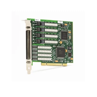
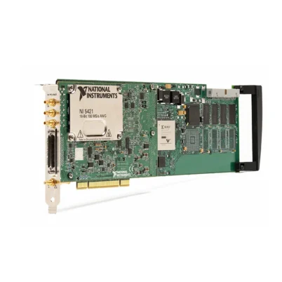
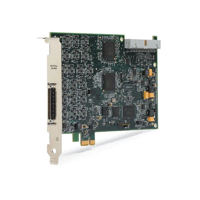
PCIe-6536B 32-Channel High-Speed Digital I/O Device
Земля PCIe-6536B is a 32-channel PCI Express digital I/O device designed for high-speed pattern generation, waveform acquisition, display testing, image-sensor interfacing and custom digital protocol applications.
It supports a maximum hardware clock rate of 25 MHz and maximum data throughput of 100 MB/s. Every digital line can be independently configured as an input or output, enabling flexible stimulus-and-response configurations.
The PCIe-6536B supports continuous streaming through the PCI Express bus, selectable digital voltage levels, change detection, hardware triggering and handshaking. It is suitable for test systems requiring more speed than the 10 MHz PCIe-6535B.
Key Features of the PCIe-6536B
- 32 bidirectional digital I/O channels
- Per-channel direction control
- 25 MHz maximum hardware clock
- 100 MB/s maximum throughput
- 40 ns minimum update interval
- 2.5 V and 3.3 V output logic families
- 5 V TTL-compatible inputs
- Up to 32 mA output drive per channel
- Continuous PCI Express streaming
- Digital pattern generation and acquisition
- Change detection and hardware handshaking
- External clocks and hardware triggers
- 68-контактный разъем VHDCI
- NI-DAQmx software support
PCIe-6536B Technical Specifications
| Product Model | PCIe-6536B |
|---|---|
| Part Numbers | 782630-01 and 153500-02L |
| Product Type | High-speed digital I/O device |
| Шинный интерфейс | PCI Express |
| Digital I/O Channels | 32 bidirectional channels |
| Direction Control | Programmable per channel |
| Maximum Clock Rate | 25 MHz |
| Maximum Throughput | 100 MB/s |
| Minimum Update Interval | 40 ns |
| Output Logic Families | 2.5 V and 3.3 V |
| Input Compatibility | 2.5 V, 3.3 V and 5 V TTL |
| Maximum Channel Current | 32 mA |
| Input Impedance | 50 kΩ |
| Signaling | Single-ended |
| Front Connector | 68-pin VHDCI |
| Operating Temperature | 0°C to 45°C |
| Software Driver | НИ-DAQmx |
PCIe-6536B Part Number and Accessories
| Item | Part Number | Описание |
|---|---|---|
| PCIe-6536B | 782630-01 | Complete 32-channel, 25 MHz PCI Express digital I/O device |
| PCIe-6536B Board-Only Kit | 153500-02L | Board-only shipping configuration |
| SHC68-C68-D4 Cable | 196275-01 | 1 m shielded digital I/O cable |
| SHC68-C68-D4 Cable | 781293-01 | 2 m shielded digital I/O cable |
| SCB-68A | 782536-01 | Shielded screw-terminal connector block |
| TBX-68 | 777141-01 | DIN-rail-mount terminal block |
| CB-68LP | 777145-01 | Low-cost unshielded connector block |
25 MHz Pattern Generation
The PCIe-6536B can update its digital state every 40 ns. Hardware timing provides consistent clock-to-data relationships for repeatable digital pattern generation.
At higher rates, signal integrity becomes increasingly important. Cable impedance, return paths, fixture layout, connectors and DUT loading can affect edge quality and timing margin.
100 MB/s Continuous Streaming
The PCI Express interface supports continuous streaming at up to 100 MB/s. Large waveform sequences can be transferred from host memory while acquisition data is returned to the application.
Computer performance, buffer configuration and competing bus activity must be considered when operating continuously at high throughput.
Per-Line Direction Control
Each channel can operate independently as an input or output. Test developers can divide the interface into address, command, response, control and status groups without being constrained by fixed port directions.
Hardware Handshaking
Hardware handshaking coordinates transfers with an external device. A transfer occurs only when the required ready and acknowledge conditions are satisfied, making the interface useful for variable-latency devices.
Digital Change Detection
Change detection can notify software when selected input lines transition. It is useful for status monitoring and event-driven tests that do not require continuous clocked acquisition.
PCIe-6536B Applications
- High-speed digital pattern generation
- Digital response acquisition
- LCD and display testing
- Image-sensor interface testing
- Protocol emulation
- Parallel memory-interface testing
- Embedded-system validation
- ASIC and FPGA functional testing
- Production automated test equipment
- Digital stimulus-response systems
- Continuous digital data streaming
FPGA and ASIC Functional Testing
The device can apply predefined command patterns to a digital DUT while simultaneously acquiring response signals. Hardware triggering coordinates the pattern with other test instruments.
Display-Panel Testing
Clocked digital data and control signals can be generated for compatible display electronics. Captured responses can be compared with expected values in the host application.
PCIe-6536B Installation Workflow
Step 1: Verify PCI Express Resources
Confirm that the computer provides a compatible PCI Express slot and sufficient sustained data-transfer performance.
Step 2: Install NI-DAQmx
Install an NI-DAQmx version supporting the PCIe-6536B before developing the digital task.
Step 3: Install the Device
Power down the host, observe ESD precautions and secure the card in the selected slot.
Step 4: Connect the Digital Fixture
Use a compatible VHDCI cable and ensure that clock and data return paths are short and clearly defined.
Step 5: Configure Direction and Voltage
Assign the direction of each line and select a voltage family compatible with the DUT.
Step 6: Verify Timing
Begin at a low clock rate, verify the pattern with an oscilloscope or logic analyzer and gradually increase the clock frequency.
PCIe-6536B Troubleshooting
Patterns work at low speed but fail at 25 MHz
Review cable length, ringing, termination, edge placement, grounding and DUT timing margins.
A digital line cannot drive the DUT
Check the selected voltage level, output-current demand and external pull resistors.
Continuous acquisition produces overflow errors
Increase buffers, read larger data blocks and confirm that the host application sustains the required transfer rate.
The DUT response is sampled on the wrong edge
Change the acquisition sample-clock edge or adjust the relative clock and data timing.
The card is detected but the task cannot start
Check for conflicting line directions, unsupported timing combinations or another application reserving the device.
PCIe-6536B Comparison
| Модель | Clock Rate | Throughput | Recommended Use |
|---|---|---|---|
| PCIe-6535B | 10 MHz | 40 MB/s | Moderate-speed digital interfaces |
| PCIe-6536B | 25 MHz | 100 MB/s | Higher-speed pattern I/O |
| PCIe-6537B | 50 MHz | 200 MB/s | Fast digital streaming |
| PCI-6534 | Legacy platform | Model dependent | Maintaining PCI-based systems |
The PCIe-6536B provides 2.5 times the maximum clock rate and throughput of the PCIe-6535B. Select the faster model when the DUT requires a clock above 10 MHz.
PCIe-6536B Frequently Asked Questions
What is the maximum PCIe-6536B clock rate?
The maximum hardware clock rate is 25 MHz.
What is the maximum throughput?
The specified maximum throughput is 100 MB/s.
Can every channel be configured independently?
Yes. Each of the 32 lines can be configured as an input or output.
Does it support 5 V logic?
It supports 5 V TTL-compatible inputs. Output voltage families should be verified against the DUT requirements.
What are the PCIe-6536B part numbers?
The complete device is 782630-01; 153500-02L identifies a board-only configuration.
Recommended Related Products
- PCIe-6535B 10 MHz Digital I/O Device
- PCIe-6537B 50 MHz Digital I/O Device
- PCI-6534 Digital I/O Device
- PXIe-6548 Digital Waveform Instrument
Request a Quote for the PCIe-6536B
Contact us for availability and project pricing for the PCIe-6536B 25 MHz digital I/O device. We can also supply compatible shielded VHDCI cables and connector blocks.















