




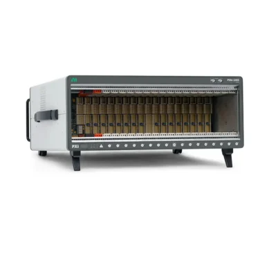

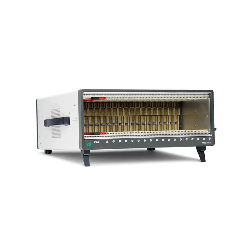
NI PXIe-1084 18-Slot PXI Express Chassis
Земля НИ PXIe-1084 is an 18-slot PXI Express chassis designed for large modular automated test, data acquisition, RF measurement and electronic validation systems. It provides one PXI Express system controller slot and 17 hybrid peripheral slots, allowing engineers to install both PXI Express modules and compatible conventional PXI modules throughout the chassis.
With maximum system bandwidth of 4 GB/s, up to 500 MB/s of bandwidth per peripheral slot, 650 W of total available DC power and as much as 58 W of cooling capacity per peripheral slot, the PXIe-1084 supports a wide selection of high-performance PXI instruments.
Two principal configurations are available. Part number 784058-01 is the standard PXIe-1084 chassis, while part number 786397-01 includes the Timing and Synchronization option with external reference-clock and trigger-routing connections.
Key Features of the PXIe-1084
- 18-slot 3U PXI Express chassis
- One PXI Express system controller slot
- 17 PXI Express hybrid peripheral slots
- All-hybrid peripheral-slot architecture
- Supports PXI Express and compatible conventional PXI modules
- Up to 4 GB/s maximum system bandwidth
- Up to 500 MB/s bandwidth per peripheral slot
- 650 W maximum total available DC power
- Up to 58 W cooling capacity per peripheral slot
- Three high-capacity module-cooling fans
- High and automatic fan-speed selection
- 10 MHz PXI reference clock
- 100 MHz PXI Express reference clock
- PXI and PXI Express trigger resources
- Optional external clock and trigger access
- Optional remote inhibit and chassis-monitoring interface
- Suitable for desktop or rack-mounted systems
- Compatible with embedded and remote PXI Express controllers
18-Slot All-Hybrid Architecture
The PXIe-1084 combines one system controller slot with 17 hybrid peripheral slots. The all-hybrid backplane gives system designers greater freedom when placing different types of instruments in the chassis.
A hybrid peripheral slot can accept a compatible PXI Express module or a conventional 32-bit PCI-based PXI module with the appropriate hybrid-compatible connector. This is useful when a test system must combine newer PXI Express instruments with existing PXI measurement, communication or switching modules.
The controller position also provides three system expansion slots for wider embedded controllers. Before selecting an embedded controller, verify its physical width, cooling requirement, power consumption and chassis compatibility.
PXI and PXI Express Module Compatibility
The PXIe-1084 supports a broad range of modular instruments, including digitizers, oscilloscopes, waveform generators, RF analyzers, source measure units, digital multimeters, data acquisition modules, communication interfaces, FPGA modules and switching instruments.
Although every peripheral slot uses a hybrid connector, individual modules still have their own bus, power, cooling and software requirements. Confirm the exact module and chassis compatibility before finalizing the system configuration.
Legacy CompactPCI modules may fit mechanically in supported configurations, but mechanical compatibility alone does not guarantee application, driver or timing compatibility.
PXIe-1084 Technical Specifications
| Product Model | PXIe-1084 |
|---|---|
| Product Type | PXI Express chassis |
| Standard Part Number | 784058-01 |
| Timing and Synchronization Part Number | 786397-01 |
| Total Slot Count | 18 slots |
| System Controller Slots | 1 system slot with 3 system expansion slots |
| Hybrid Peripheral Slots | 17 |
| Dedicated PXI Express Peripheral Slots | 0 |
| Dedicated Conventional PXI Slots | 0 |
| System Timing Slot | No dedicated system timing slot |
| Maximum System Bandwidth | 4 GB/s |
| Maximum Peripheral-Slot Bandwidth | Up to 500 MB/s per slot |
| Maximum Total Available Power | 650 W |
| Maximum Controller Power Dissipation | 140 W |
| Maximum Peripheral-Slot Power Dissipation | 58 W per slot |
| Module Cooling | Three 210 CFM fans with High and Auto speed selection |
| Secondary Cooling | One 70 CFM fan |
| Module Airflow Direction | Bottom of module to top of module |
| Onboard Clock Type | VCXO |
| PXI Reference Clock | 10 MHz PXI_CLK10 |
| PXI Express Reference Clock | 100 MHz PXIe_CLK100 with PXIe_SYNC100 |
| PXI_CLK10 Accuracy | ±25 ppm maximum |
| PXI_CLK10 Slot-to-Slot Skew | 250 ps maximum |
| PXIe_CLK100 Accuracy | ±25 ppm maximum |
| PXIe_CLK100 Slot-to-Slot Skew | 100 ps maximum |
| External Clocking | Available with the Timing and Synchronization option |
| External Trigger Access | Available with the Timing and Synchronization option |
| Power Supply Type | AC |
| AC Input Rating | 100 V to 240 VAC, 50/60 Hz, 10 A to 5 A |
| 400 Hz Input Support | 100 V to 120 VAC, 400 Hz, 10 A |
| Operating Voltage Range | 90 V to 264 VAC |
| Operating Frequency Range | 47 Hz to 440 Hz |
| Typical Power-Supply Efficiency | 85% |
| Operating Temperature at Up to 38 W per Slot | 0°C to 50°C |
| Operating Temperature at Up to 58 W per Slot | 0°C to 40°C |
| Operating Humidity | 10% to 90% RH, noncondensing |
| Storage Temperature | −40°C to 71°C |
| Maximum Altitude | 2,000 m at 25°C ambient temperature |
| Dimensions | 177.1 × 445.5 × 463.6 mm |
| Weight | 13.5 kg |
| Module Format | 3U PXI and PXI Express |
4 GB/s System Bandwidth
The PXIe-1084 provides maximum aggregate system bandwidth of 4 GB/s. Each peripheral slot supports up to 500 MB/s, depending on the installed controller, module interface and backplane connection.
This bandwidth is suitable for many automated test, data acquisition and mixed-instrument systems. Applications containing multiple high-speed digitizers, RF instruments or continuous streaming modules should calculate the combined data rate before selecting the chassis.
The maximum system bandwidth is shared across the chassis architecture. A module’s theoretical PCI Express interface rate does not guarantee the same sustained rate when several instruments transfer data simultaneously.
650 W Power Supply
The PXIe-1084 supplies up to 650 W of total DC power to the controller and installed peripheral modules. The system controller position supports as much as 140 W of power dissipation, while each peripheral slot supports a maximum of 58 W under the specified environmental conditions.
System designers should calculate consumption across every voltage rail rather than relying only on total wattage. A valid system must remain within the chassis-wide power rating, individual rail-current limits and per-slot limits at the same time.
DC Output Rails
| Voltage Rail | Максимальный ток | Load Regulation |
|---|---|---|
| +12 V | 54.1 A | ±5% |
| +5 V | 51.1 A | ±5% |
| +3.3 V | 60 A | ±5% |
| −12 V | 4.25 A | ±5% |
| +5 V Auxiliary | 4.1 A | ±5% |
All DC outputs include protection against overload and short-circuit conditions with automatic recovery. The +12 V, +5 V and +3.3 V rails also include overvoltage clamping.
58 W Per-Slot Cooling Capacity
The chassis uses three 210 CFM fans to create positive-pressure airflow through the installed modules. Air enters at the bottom rear and passes from the bottom to the top of each module before leaving through the top of the chassis.
A separate 70 CFM fan provides secondary cooling, and the power supply includes its own integrated fans. This cooling architecture supports modules dissipating up to 58 W per peripheral slot when the ambient temperature is between 0°C and 40°C.
At ambient temperatures up to 50°C, peripheral-module power dissipation should remain at or below 38 W per slot. The power consumption and airflow requirements of every installed module should be reviewed before operation at elevated temperatures.
High and Automatic Fan Modes
The fan selector allows the chassis to operate in automatic or high-speed mode. Automatic mode adjusts cooling according to internal conditions and can reduce acoustic noise under lighter loads.
High-speed mode provides maximum airflow and is recommended when the system contains high-power instruments, operates in a warm environment or is installed in a rack with restricted ventilation.
Required Cooling Clearance
| Chassis Area | Minimum Clearance |
|---|---|
| Above the chassis | 44.45 mm |
| Behind the chassis | 101.60 mm |
| Each side | 44.45 mm |
Do not place cables, rack panels or other equipment over the air intake or exhaust openings. Inadequate clearance can increase module temperature, reduce measurement stability and cause thermal shutdown.
PXI Timing and Synchronization
The PXIe-1084 distributes both PXI_CLK10 and PXIe_CLK100 reference clocks across its backplane. These clocks provide a common timing reference that compatible modules can use for coordinated measurements and generation.
The 10 MHz PXI_CLK10 reference has maximum slot-to-slot skew of 250 ps. The 100 MHz PXIe_CLK100 reference provides maximum slot-to-slot skew of 100 ps. PXI and PXI Express trigger resources also support coordinated multi-instrument operation.
Optional External Clock and Trigger Routing
Part number 786397-01 adds the Timing and Synchronization option. This configuration provides rear-panel external 10 MHz reference input and output connections, external trigger access, programmable function interfaces, remote inhibit control and chassis fault monitoring.
The option is useful when the PXIe-1084 must synchronize with another chassis, a standalone instrument or an external reference source. Part number 784058-01 does not include the same external timing and trigger-access connections.
External 10 MHz Reference Input
The optional rear-panel SMA reference input accepts a 10 MHz signal within ±25 ppm. It supports sine-wave or square-wave inputs from 100 mVpp to 5 Vpp and has a nominal 50 Ω input impedance.
When using an external reference, verify the source amplitude, frequency accuracy, impedance and cable quality. A stable common reference helps control long-term timing and frequency relationships between instruments.
Remote Inhibit and Chassis Monitoring
The Timing and Synchronization option includes a rear-panel interface for remote inhibit, chassis fault output and programmable digital lines. Remote inhibit can be used to control chassis power from an external system or safety circuit.
The fault signal can notify external control equipment of a detected chassis condition. The exact electrical interface and logic behavior should be confirmed before integrating it into an interlock or production system.
PXIe-1084 Part Number and Accessories
| Item | Part Number | Описание |
|---|---|---|
| PXIe-1084 Standard Chassis | 784058-01 | 18-slot chassis with 17 hybrid slots, 4 GB/s bandwidth and VCXO timing |
| PXIe-1084 with Timing and Synchronization | 786397-01 | Adds external clocking, external trigger access, remote inhibit and monitoring connections |
| Rack-Mount Kit | Configuration dependent | Allows front-facing or rear-facing installation in a standard equipment rack |
| Chassis Filler Panels | Configuration dependent | Covers unused slots and helps preserve airflow and EMC performance |
| PXI Express Embedded Controller | Model dependent | Provides local processing and system control from the controller slot |
| PXI Express Remote-Control Module | Model dependent | Connects the chassis to an external desktop, workstation or server |
| Timing and Trigger Cables | Configuration dependent | Used with the optional rear-panel reference and trigger interfaces |
PXIe-1084 Configuration Selection
Choose part number 784058-01 when the system uses only the chassis backplane clocks and trigger resources. This configuration is appropriate for many self-contained PXI systems using one chassis.
Choose part number 786397-01 when external reference-clock connections, external trigger access, remote power control or chassis monitoring are required. Confirm the complete part number because the two configurations share the same PXIe-1084 model name.
Embedded Controller Selection
The PXIe-1084 can use a compatible PXI Express embedded controller such as the PXIe-8822, PXIe-8842, PXIe-8862 or another supported controller.
Controller selection should consider processor performance, memory, storage capacity, operating system, physical width, PCI Express interface capability and software compatibility.
Remote-Control Configuration
Instead of an embedded controller, the chassis can be connected to an external computer through a compatible PXI Express remote-control interface. This approach allows the test system to use a desktop computer, industrial PC, workstation or server.
Both host-side and chassis-side interfaces, as well as the connecting cable, must belong to a compatible remote-control system. Data bandwidth can be limited by the lowest-performance component in the connection.
Rack-Mount Installation
The PXIe-1084 includes symmetrical mounting locations that support front-facing or rear-facing rack installation with the appropriate kit. Rear-facing installation can simplify cable access in certain production or laboratory racks.
The rack design must support the 13.5 kg chassis weight and maintain the required intake and exhaust clearance. Heavy front-panel cables should use independent strain relief rather than placing their full weight on instrument connectors.
Filler Panels
Install approved filler panels over unused slots. Filler panels help direct cooling air through occupied slots, reduce recirculation and support the chassis EMC configuration.
Operating with multiple uncovered slots can allow air to bypass installed instruments, causing individual modules to run hotter even when the chassis fans are operating normally.
PXIe-1084 Applications
- Автоматизированное испытательное оборудование
- Production functional testing
- High-channel-count data acquisition
- Electronic device validation
- РФ и беспроводное тестирование
- Симуляция с аппаратным входом
- Aerospace and defense test systems
- Automotive controller testing
- Semiconductor characterization
- Power electronics testing
- Research and laboratory measurement
- Mixed PXI and PXI Express systems
- Multichassis synchronized measurement
- Industrial monitoring and control
Automated Test Equipment
The 17 hybrid peripheral slots allow the PXIe-1084 to combine many instrument types in one chassis. A system can include switching modules, digital multimeters, source measure units, waveform generators, digitizers and communication interfaces under centralized software control.
This modular architecture helps production and validation teams replace individual instruments without rebuilding the entire test station.
High-Channel-Count Data Acquisition
Multiple PXI and PXI Express acquisition modules can be installed to create systems with hundreds of measurement channels. Common backplane clocks and triggers help coordinate measurements across the installed devices.
The expected aggregate data rate must remain compatible with the chassis, controller, storage device and measurement software. Continuous high-speed streaming can require a higher-bandwidth chassis than event-based or lower-rate acquisition.
RF and Wireless Testing
The PXIe-1084 can house RF signal generators, vector signal analyzers, RF switches and related modules for wireless-device and RF-component testing.
For systems using several high-bandwidth RF instruments simultaneously, compare the expected traffic with the chassis’s 4 GB/s maximum system bandwidth. A PXIe-1085 or PXIe-1095 may be more appropriate when substantially higher aggregate bandwidth is required.
Hardware-in-the-Loop Testing
Hardware-in-the-loop systems can combine FPGA modules, vehicle communication interfaces, analog I/O, digital I/O and fault-insertion hardware in the PXIe-1084.
Backplane timing resources support coordinated signal generation and acquisition, while the large slot count allows complex controller-test systems to remain within one modular chassis.
Aerospace and Defense Systems
The PXIe-1084 can provide the chassis platform for avionics interface simulation, radar subsystem validation, communication testing and automated electronic verification.
The 100 V to 120 V, 400 Hz AC input support can be useful in environments where 400 Hz power is available. The complete installation must still satisfy the project’s grounding, isolation, environmental and safety requirements.
Mixed-Generation PXI Systems
Because all 17 peripheral slots are hybrid compatible, the PXIe-1084 is useful when preserving investment in conventional PXI instruments while adding newer PXI Express hardware.
Before migrating a legacy module, verify that its connector is hybrid-slot compatible and that a supported driver is available for the selected operating system.
Synchronized Multichassis Systems
The timing and synchronization version can exchange a 10 MHz reference and external triggers with additional chassis or standalone instruments. This enables larger distributed systems to share a common timing source.
Reference-clock sharing improves frequency coherence, but precise sample alignment can also require trigger-delay characterization, calibration and module-specific synchronization procedures.
PXIe-1084 Installation Workflow
Step 1: Confirm the Chassis Configuration
Check whether the system requires the standard 784058-01 chassis or the 786397-01 Timing and Synchronization version. Verify the controller, module, bandwidth, timing and external-interface requirements before installation.
Step 2: Calculate System Power and Cooling
Add the power consumption of the controller and all peripheral modules. Check total power, voltage-rail current and per-slot dissipation separately.
Modules dissipating up to 58 W per slot require an operating temperature of 0°C to 40°C. At temperatures up to 50°C, limit peripheral-slot dissipation to 38 W or less.
Step 3: Prepare the Installation Location
Place the chassis on a stable surface or install it using a compatible rack-mount kit. Provide at least 44.45 mm of clearance above and on each side, plus 101.60 mm behind the chassis.
Do not block the bottom-rear air intake, top exhaust, side ventilation or power-supply cooling openings.
Step 4: Connect Protective Earth and AC Power
Use a correctly grounded AC outlet and an approved power cord. Confirm that the local mains voltage and frequency fit within the chassis input ratings.
The AC power cord is the primary means of completely disconnecting mains power, so it must remain accessible after installation.
Step 5: Power Down Before Installing Modules
Turn off the chassis and disconnect the power cord before installing or removing the controller, remote-control module or peripheral instruments. Follow ESD precautions and handle modules only by their edges or approved hardware.
Step 6: Install the System Controller
Install the embedded controller or remote-control interface in the system controller position. Ensure that wider controllers occupy only the designated expansion area and do not interfere with peripheral slots.
Step 7: Install Peripheral Modules
Place each instrument in a compatible hybrid slot and tighten its retaining screws. Consider cable routing, module heat dissipation, timing resources and data-path requirements when choosing slot locations.
Step 8: Install Filler Panels
Cover every unused peripheral slot with a filler panel. This maintains the intended pressure and airflow through occupied modules.
Step 9: Connect Timing Interfaces
For the 786397-01 version, connect the external reference, trigger or monitoring interfaces as required. Confirm 50 Ω termination and signal-level compatibility before enabling external sources.
Step 10: Start and Verify the System
Power on the chassis and verify fan operation, power indicators and controller startup. Open NI Measurement & Automation Explorer and confirm that the chassis and all installed modules are detected correctly.
Step 11: Validate Synchronization and Throughput
Run measurement tests that represent the intended operating load. Confirm trigger timing, clock selection, sustained data transfer, module temperature and storage performance before placing the system into service.
PXIe-1084 Troubleshooting
The PXIe-1084 Does Not Power On
Confirm that the AC cable is connected to a working grounded outlet and that the rear and front power controls are in the required positions. Check the external power source, cable and chassis indicators.
The internal input fuse is not intended to be replaced as a normal field-service procedure. If the chassis remains inactive, remove installed modules and contact qualified service personnel.
The Controller Does Not Start
Power down the chassis and reseat the embedded controller or remote-control module. Check memory, storage devices, display connections and controller status indicators.
For remotely controlled systems, verify the host interface, connection cable, power-up sequence and required NI system software.
Installed Modules Are Not Detected
Refresh the device list in NI MAX and verify that each module is fully seated. Check driver installation and operating-system support. Move one affected module to another compatible slot to help distinguish a module problem from a slot or configuration problem.
A Conventional PXI Module Does Not Fit
Not every conventional PXI module has a hybrid-compatible connector. Do not modify the module or force it into the slot. Check the module’s connector type and hybrid-slot compatibility documentation.
The Chassis Reports an Overtemperature Condition
Check all intake and exhaust openings, fan operation, ambient temperature and rack clearance. Confirm that filler panels are installed and that individual modules do not exceed the permitted slot-cooling capacity.
Select high fan mode when additional cooling is required. Shut down the system if a fan has failed or if normal airflow cannot be restored.
Fan Noise Is Higher Than Expected
The fans may increase speed as the chassis temperature or installed load rises. Verify that the fan selector is not set to High and that ventilation openings are not restricted.
High acoustic output can be normal when high-power modules require maximum cooling. Do not reduce airflow solely to lower noise.
Data Transfer Is Slower Than Expected
Review the bandwidth of the controller, individual modules, chassis backplane and storage system. The PXIe-1084 provides up to 4 GB/s aggregate system bandwidth and up to 500 MB/s per peripheral slot.
Several modules transferring data simultaneously can share an upstream connection. Reduce acquisition rates, use onboard memory or select a higher-bandwidth chassis when required.
Modules Do Not Synchronize Correctly
Confirm that every instrument uses the intended reference clock and trigger source. Check trigger routing, chassis configuration, cable length, module driver settings and application initialization order.
The External 10 MHz Reference Is Not Detected
This interface is available only on the Timing and Synchronization configuration. Verify that the chassis is part number 786397-01 and that the source supplies 10 MHz within ±25 ppm at an amplitude between 100 mVpp and 5 Vpp.
Remote Inhibit Does Not Control Chassis Power
Confirm that the chassis includes the optional rear-panel interface and that the inhibit-mode switch is correctly configured. Verify the external signal level, ground reference, connector wiring and logic polarity.
The System Becomes Unstable Under Full Load
Calculate total power and voltage-rail current for the complete installation. Check module temperature and verify that the ambient environment complies with the 38 W or 58 W operating profile.
Also inspect the controller, storage and host-transfer architecture because system instability may originate from software, memory or data-throughput limitations rather than the chassis.
PXIe-1084 Comparison
| Модель | Slots | Maximum System Bandwidth | Slot Cooling | Best Suited For |
|---|---|---|---|---|
| PXIe-1084 | 18 total, 17 hybrid | 4 GB/s | 58 W | Large mixed PXI/PXIe systems with moderate aggregate bandwidth |
| PXIe-1085 | 18 total | 24 ГБ/с | 38 Вт | High-throughput digitizer, RF and data-streaming systems |
| PXIe-1086 | 18 total | 12 GB/s | 38 Вт | Large systems requiring higher bandwidth and redundant hardware support |
| PXIe-1088 | 9 total, 8 hybrid | 8 GB/s | 58 W | Medium-size systems requiring high-power module cooling |
| PXIe-1092 | 10 total | 24 ГБ/с | 82 Вт | Compact high-bandwidth systems with high-power instruments |
| PXIe-1095 | 18 total | 24 ГБ/с | 82 Вт | Large, high-bandwidth systems using demanding PXIe instruments |
PXIe-1084 vs PXIe-1085
Both chassis provide 18 slots, but the PXIe-1085 increases maximum system bandwidth from 4 GB/s to 24 GB/s. The PXIe-1084 provides 17 hybrid peripheral slots and up to 58 W of cooling per slot, while the PXIe-1085 uses a different slot configuration and provides 38 W per-slot cooling.
Choose the PXIe-1084 when hybrid-slot flexibility, higher per-slot cooling and a lower-bandwidth large chassis meet the application. Choose the PXIe-1085 when multiple high-speed modules must transfer substantial data simultaneously.
PXIe-1084 vs PXIe-1086
The PXIe-1086 provides up to 12 GB/s system bandwidth compared with 4 GB/s for the PXIe-1084. The PXIe-1086 also supports redundant hardware options but has a lower 38 W per-slot cooling rating.
Земля PXIe-1086 is better suited to large systems requiring higher bandwidth or redundancy. The PXIe-1084 is appropriate when all-hybrid placement flexibility and 58 W cooling are more important.
PXIe-1084 vs PXIe-1088
The PXIe-1088 has nine total slots and 8 GB/s maximum system bandwidth. The PXIe-1084 offers almost twice as many peripheral slots but provides 4 GB/s maximum aggregate bandwidth.
Select the PXIe-1084 for large module counts. Choose the PXIe-1088 when a smaller chassis with greater aggregate bandwidth is preferred.
PXIe-1084 vs PXIe-1095
The PXIe-1095 is a newer 18-slot chassis with up to 24 GB/s system bandwidth and as much as 82 W of cooling per slot. It is designed for particularly demanding high-performance PXI Express instrumentation.
Земля PXIe-1095 is preferred for wideband RF systems, high-speed digitizers, FPGA instruments and other high-throughput configurations. The PXIe-1084 remains suitable for mixed PXI/PXIe systems that do not require the newer chassis’s bandwidth and cooling capability.
Recommended Related Products
- PXIe-1085 18-Slot High-Bandwidth PXI Express Chassis
- PXIe-1086 18-Slot PXI Express Chassis
- PXIe-1088 9-Slot PXI Express Chassis
- PXIe-1092 High-Performance PXI Express Chassis
- PXIe-1095 18-Slot High-Performance PXI Express Chassis
- Встроенный контроллер PXIe-8822
- PXIe-8842 Embedded Controller
- PXIe-8862 Embedded Controller
- View More NI PXI and PXI Express Chassis
Selecting the Right PXI Express Chassis
Choose the PXIe-1084 when the system needs 17 flexible hybrid peripheral slots, up to 58 W of cooling per slot and no more than 4 GB/s aggregate bandwidth.
Consider the PXIe-1085 or PXIe-1095 when several high-speed digitizers, RF instruments or FPGA modules must stream data simultaneously. Consider a smaller chassis when the system uses fewer modules and rack space or portability is more important than expansion capacity.
Why Choose the PXIe-1084?
- Provides 17 hybrid peripheral slots in one chassis
- Accepts compatible PXI and PXI Express modules
- Supports up to 4 GB/s aggregate system bandwidth
- Offers up to 58 W of cooling per peripheral slot
- Provides 650 W of total available power
- Supports embedded or remote-control architectures
- Distributes PXI and PXI Express reference clocks
- Offers an optional timing and synchronization configuration
- Supports desktop and rack-mounted installations
- Provides a flexible platform for large automated test systems
PXIe-1084 Frequently Asked Questions
What is the PXIe-1084?
The PXIe-1084 is an 18-slot PXI Express chassis with one system controller slot, 17 hybrid peripheral slots, up to 4 GB/s system bandwidth and 650 W of available power.
What are the PXIe-1084 part numbers?
Part number 784058-01 identifies the standard configuration. Part number 786397-01 identifies the version with the Timing and Synchronization option.
How many peripheral slots does the PXIe-1084 provide?
It provides 17 hybrid peripheral slots in addition to its system controller position.
Can the PXIe-1084 accept conventional PXI modules?
Yes. Its hybrid peripheral slots can accept compatible conventional PXI modules as well as PXI Express modules. The individual module must have a hybrid-compatible connector.
What is the maximum PXIe-1084 system bandwidth?
The maximum aggregate system bandwidth is 4 GB/s. Individual peripheral slots support up to 500 MB/s.
Does the PXIe-1084 have a system timing slot?
No. It does not have a dedicated system timing slot, although the chassis provides PXI and PXI Express backplane timing and trigger resources.
What does the Timing and Synchronization option add?
It adds external 10 MHz reference input and output connections, external trigger access, remote inhibit control, chassis fault monitoring and programmable digital interfaces.
What is the maximum available chassis power?
The PXIe-1084 provides up to 650 W of total DC output power, subject to the individual voltage-rail and slot limits.
How much cooling is available per slot?
The chassis supports up to 58 W of peripheral-slot cooling from 0°C to 40°C. At ambient temperatures up to 50°C, the supported profile is up to 38 W per slot.
Can the PXIe-1084 use an embedded controller?
Yes. A compatible PXI Express embedded controller can be installed in the system controller position.
Can it be controlled by an external computer?
Yes. A compatible remote-control interface can connect the chassis to an external desktop computer, workstation, industrial PC or server.
Can the PXIe-1084 be rack mounted?
Yes. Compatible rack-mount kits can be installed for either front-facing or rear-facing chassis orientation.
Does the PXIe-1084 support 400 Hz AC power?
Yes. It supports 400 Hz operation when the AC input is between 100 V and 120 V. The complete operating frequency range is 47 Hz to 440 Hz.
Can several PXIe-1084 chassis be synchronized?
Yes. The 786397-01 Timing and Synchronization version provides external reference and trigger connections that can be used in compatible multichassis timing architectures.
Is the PXIe-1084 suitable for high-speed digitizers?
It can support compatible high-speed digitizers, but the complete system must remain within the 4 GB/s aggregate bandwidth and 500 MB/s per-slot capability. A higher-bandwidth chassis may be more appropriate for multiple continuously streaming digitizers.
Are filler panels required?
Filler panels are strongly recommended for unused slots because they preserve the intended airflow and help maintain EMC performance.
What should be verified before ordering?
Confirm the exact part number, timing option, controller type, module compatibility, bandwidth requirement, total power, per-slot cooling, rack hardware and required external timing accessories.
Request a Quote for the PXIe-1084
Contact us for current availability, lead time and project pricing for the NI PXIe-1084 18-Slot PXI Express Chassis. Please specify whether you require part number 784058-01 or the 786397-01 Timing and Synchronization version.
We can also help select compatible PXI Express embedded controllers, remote-control interfaces, rack-mount hardware, filler panels and related PXI measurement modules for your automated test system.















