




PXIe-5442 100 MS/s 16-Bit PXI Express Arbitrary Waveform Generator
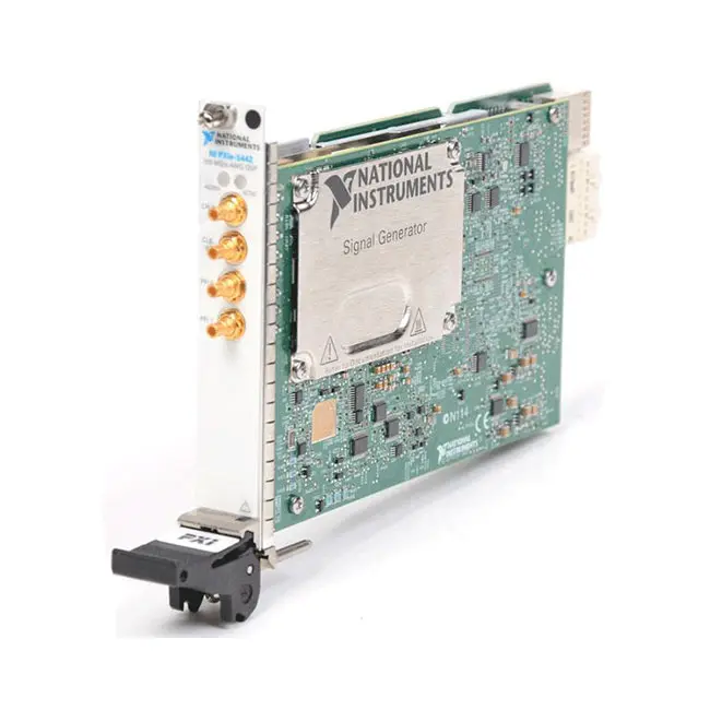
Земля NI PXIe-5442 is a single-channel PXI Express arbitrary waveform generator designed for communications testing, IF signal generation, electronic validation and automated stimulus-response systems. It combines 16-bit output resolution, a 100 MS/s sampling rate and greater than 43 MHz analog bandwidth in a compact one-slot PXI Express module.
The PXIe-5442 includes onboard signal processing with as much as 40 MHz of digital upconverter bandwidth. Its processing architecture supports real and complex I/Q data, programmable interpolation, pulse-shaping filters, digital gain, offset adjustment and numerically controlled oscillator frequency translation.
Key Features of the PXIe-5442
- Single analog waveform output channel
- 16-bit digital-to-analog converter resolution
- 100 MS/s internal sampling rate
- Up to 105 MS/s with a supported external clock
- Up to 400 MS/s effective DAC rate with interpolation
- Greater than 43 MHz analog bandwidth
- 40 MHz maximum complex onboard signal-processing bandwidth
- Up to 43 MHz sine-wave output
- Up to 25 MHz square-wave output
- Up to 5 MHz triangle and ramp output
- 2 Vpk-pk maximum output into a 50 Ω load
- 4 Vpk-pk maximum amplitude into an open load
- Software-selectable Main and Direct output paths
- Software-selectable 50 Ω or 75 Ω output impedance
- 0 dB to 51 dB programmable attenuation
- 32 MB, 256 MB or 512 MB onboard memory
- Arbitrary waveform and arbitrary sequence generation
- Waveform linking, looping and scripting
- Real and complex I/Q data-processing modes
- Flat, raised-cosine and root-raised-cosine filters
- 48-bit numerically controlled oscillator
- Single, continuous, stepped and burst trigger modes
- Front-panel and PXI backplane triggering
- Marker and data-marker event outputs
- External sample-clock and reference-clock support
- PXI_CLK10 and NI-TClk synchronization
- Onboard self-calibration
- NI-FGEN software support
PXIe-5442 Technical Specifications
| Product Model | PXIe-5442 |
|---|---|
| Product Type | PXI Express arbitrary waveform generator with onboard signal processing |
| Number of Analog Output Channels | 1 |
| DAC Resolution | 16 bits |
| Internal Sampling Rate | Up to 100 MS/s |
| External Clock Sampling Rate | Up to 105 MS/s |
| Maximum Effective DAC Rate | 400 MS/s with interpolation |
| Analog Bandwidth | Greater than 43 MHz, measured at −3 dB |
| Maximum Complex OSP Bandwidth | 40 MHz with a 50 MS/s complex I/Q rate |
| Maximum Sine Frequency | 43 MHz |
| Maximum Square Frequency | 25 MHz using the Main path |
| Maximum Triangle Frequency | 5 MHz |
| Maximum Ramp Frequency | 5 MHz |
| Maximum Noise Frequency | 5 MHz pseudorandom noise |
| Maximum User-Defined Frequency | 43 MHz |
| Main Path Amplitude into 50 Ω | 5.64 mVpk-pk to 2 Vpk-pk |
| Main Path Amplitude into 1 kΩ | 10.7 mVpk-pk to 3.81 Vpk-pk |
| Main Path Amplitude into Open Load | 11.3 mVpk-pk to 4 Vpk-pk |
| Direct Path Amplitude into 50 Ω | 0.707 Vpk-pk to 1 Vpk-pk |
| DC Offset Range | ±25% of the selected amplitude range on the Main path |
| Output Impedance | Software-selectable 50 Ω or 75 Ω |
| Output Coupling | DC |
| DAC Interpolation | 1×, 2×, 4× or 8× |
| OSP Interpolation | 1× to 16,384×, depending on the selected increment range |
| Onboard Memory | 32 MB, 256 MB or 512 MB |
| Generation Modes | Standard function, arbitrary waveform, arbitrary sequence and script |
| Standard Function Frequency Resolution | 355 nHz |
| Standard Function Phase Resolution | 0.0055° |
| NCO Frequency Range | 1 mHz to 0.43 × sample rate |
| NCO Tuning Speed | 1 ms |
| Trigger Modes | Single, continuous, stepped and burst |
| Minimum Start-Trigger Pulse Width | 25 ns |
| Reference Clock Range | 5 MHz to 20 MHz in 1 MHz increments |
| Internal Clock Accuracy | ±25 ppm |
| Analog Output Connector | SMB jack |
| Clock Input Connector | SMB jack |
| PFI Connectors | 2 × bidirectional SMB jacks |
| Calibration Interval | 2 years |
| Warm-Up Time | 15 minutes |
| Typical Power Consumption | 28.3 W |
| Maximum Power Consumption | 33 W |
| Operating Temperature | 0°C to 55°C |
| Dimensions | 21.6 × 2.0 × 13.0 cm |
| Weight | 405 g |
| Module Format | 3U, one-slot PXI Express module |
| Software Driver | NI-FGEN |
PXIe-5442 Part Numbers and Memory Options
| Part Number | Onboard Memory | Описание |
|---|---|---|
| 780109-01 | 32 MB | PXIe-5442 100 MS/s arbitrary waveform generator with onboard signal processing |
| 780109-02 | 256 MB | PXIe-5442 with expanded waveform and sequence memory |
| 780109-03 | 512 MB | PXIe-5442 with maximum onboard memory configuration |
The three versions provide the same fundamental analog output and onboard processing functions. Their primary difference is onboard waveform-memory capacity. Confirm the complete part number and required waveform duration before ordering.
PXIe-5442 Connection Accessories
| Accessory Type | Recommended Configuration | Приложение |
|---|---|---|
| Analog Output Cable | 50 Ω SMB-to-SMB or SMB-to-BNC cable | Connects CH 0 to a DUT, RF upconverter or measurement system |
| Reference Clock Cable | 50 Ω SMB cable | Connects an external reference or sample clock to CLK IN |
| Trigger Cable | SMB digital-signal cable | Connects external triggers and marker events through PFI 0 or PFI 1 |
| Шасси PXI Express | Compatible 3U PXI Express chassis | Provides power, cooling, PXI_CLK10 and backplane triggering |
Use controlled-impedance cables appropriate for the required bandwidth. Confirm the connector type, cable impedance, length and termination before connecting the module to a DUT or RF upconverter.
Single-Channel 16-Bit Architecture
The PXIe-5442 provides one 16-bit analog output channel through the CH 0 SMB connector. Its 65,536 DAC codes enable precise generation of standard and application-specific waveforms.
The single-channel architecture is optimized for high-quality baseband and intermediate-frequency stimulus rather than general multichannel analog output. Multiple modules can be synchronized when additional phase-coherent channels are required.
100 MS/s Waveform Generation
The internal sample clock supports rates from 10 S/s to 100 MS/s in high-resolution mode. Divide-by-N clocking provides rates derived from the 100 MHz timebase, while a compatible external source can operate the sample clock at up to 105 MS/s.
Flexible clock selection allows engineers to prioritize frequency resolution, low jitter or synchronization with another instrument according to the test application.
400 MS/s Effective DAC Rate
The DAC interpolation filter supports 2×, 4× and 8× interpolation. With an appropriate sample rate and interpolation setting, the effective DAC rate can reach 400 MS/s.
Interpolation produces additional calculated samples between the original waveform points and helps suppress unwanted spectral images. The 400 MS/s value is the effective DAC update rate rather than the maximum user-waveform download rate.
43 MHz Analog Bandwidth
The PXIe-5442 offers greater than 43 MHz analog bandwidth and supports sine and user-defined waveform frequencies up to 43 MHz. This performance makes the module suitable for baseband, IF, communications and frequency-domain testing.
Actual system bandwidth also depends on cable loss, impedance matching, external switching, DUT loading and the selected analog output path.
Main and Direct Output Paths
Main Output Path
The Main path provides amplitudes from 5.64 mVpk-pk to 2 Vpk-pk into 50 Ω. It supports programmable DC offset, 50 Ω or 75 Ω impedance and an optional seven-pole analog filter.
This path is suitable for standard functions, time-domain signals and applications requiring flexible low-level output adjustment.
Direct Output Path
The Direct path provides 0.707 Vpk-pk to 1 Vpk-pk into 50 Ω and is optimized for intermediate-frequency and frequency-domain applications. It offers a fast typical rise and fall time below 5 ns.
DC offset is not available on the Direct path. Select the Main path when the waveform must be shifted around a programmable DC bias.
Programmable Amplitude and Offset
The PXIe-5442 delivers up to 2 Vpk-pk into a 50 Ω load through the Main path. The maximum amplitude increases to approximately 3.81 Vpk-pk into 1 kΩ or 4 Vpk-pk into an open load.
The Main-path DC offset span is ±25% of the selected amplitude range. NI-FGEN can compensate the output amplitude according to the user-configured resistive load.
50 Ω and 75 Ω Output Impedance
The output impedance is software-selectable between 50 Ω and 75 Ω. The 50 Ω setting is commonly used for RF, IF and laboratory measurement systems, while 75 Ω is useful for compatible video and communications equipment.
Incorrect load configuration can cause the voltage at the DUT to differ from the programmed amplitude. Always configure the actual load impedance and use matching cables and terminations.
Standard Function Generation
The PXIe-5442 generates sine, square, triangle, ramp-up, ramp-down, DC, pseudorandom noise and user-defined functions. Standard functions can be programmed without downloading a long arbitrary waveform record.
| Waveform | Maximum Recommended Frequency |
|---|---|
| Sine | 43 MHz |
| Square | 25 MHz |
| Triangle | 5 MHz |
| Ramp Up | 5 MHz |
| Ramp Down | 5 MHz |
| Pseudorandom Noise | 5 MHz |
| User Defined | 43 MHz |
Arbitrary Waveform Generation
Arbitrary waveform mode generates a user-created waveform stored in onboard memory. Custom data can reproduce modulated signals, transient events, sensor outputs, pulses and other nonstandard stimulus patterns.
The minimum waveform size is 16 samples in supported single and continuous configurations. Waveform sizes and sequence requirements vary according to the trigger mode and sample rate.
Arbitrary Sequence and Script Generation
Arbitrary sequence mode allows multiple stored waveforms to be generated in a specified order. Each sequence segment can define a waveform, repetition count and marker position.
Script generation adds conditional triggering, looping and waveform-linking capabilities. These features allow complex test patterns to be assembled from reusable waveform segments without duplicating all waveform data in memory.
Onboard Memory Capacity
| Memory Version | Maximum Arbitrary Waveform Samples | Maximum Play Time at 100 MS/s |
|---|---|---|
| 32 MB | Approximately 16.78 million samples | Approximately 0.16 seconds |
| 256 MB | Approximately 134.22 million samples | Approximately 1.34 seconds |
| 512 MB | Approximately 268.44 million samples | Approximately 2.68 seconds |
Waveform playback can be extended substantially through looping, sequencing and onboard interpolation. Complex I/Q data uses two components per sample, so the available waveform duration is lower than for real-valued data.
Onboard Signal Processing
The PXIe-5442 incorporates onboard signal processing for real and complex I/Q waveform generation. Processing operations occur inside the module, reducing the amount of waveform data that must be stored or transferred by the system controller.
The OSP architecture includes programmable interpolation, prefilter gain, prefilter offset, pulse-shaping filters, an NCO and digital I/Q mixing for frequency translation.
40 MHz Digital Upconverter Bandwidth
With a 50 MS/s complex I/Q rate, the onboard signal-processing system provides up to 40 MHz of complex bandwidth. Real-mode flat bandwidth is approximately 0.4 times the I/Q rate, while complex-mode flat bandwidth is approximately 0.8 times the I/Q rate.
This capability is useful for generating wideband digitally modulated signals at an intermediate frequency before external RF upconversion.
Onboard Interpolation
OSP interpolation factors extend from 1× to 16,384× using supported step sizes. High interpolation factors allow relatively low-rate baseband I/Q waveforms to be converted into higher-rate DAC data without software-generated oversampling.
Total interpolation combines OSP interpolation with the selected DAC interpolation factor.
Pulse-Shaping Filters
The PXIe-5442 provides flat, raised-cosine and root-raised-cosine FIR filter options. Raised-cosine filters are commonly used for controlling occupied bandwidth and intersymbol interference in digital communications signals.
Filter parameters such as alpha can be configured according to the required modulation standard and signal characteristics.
Numerically Controlled Oscillator
The onboard numerically controlled oscillator supports frequencies from 1 mHz to 0.43 times the sample rate. Its frequency resolution is determined by the sample rate divided by 248, providing 355 nHz resolution at 100 MS/s.
The NCO supports independent I and Q phase configuration with 0.0055° phase resolution and a typical tuning speed of 1 ms.
I/Q Signal Generation
The PXIe-5442 can accept complex I/Q waveform data and digitally translate it to a programmed intermediate frequency. This makes it suitable for generating QPSK, QAM, MSK and other digitally modulated signals.
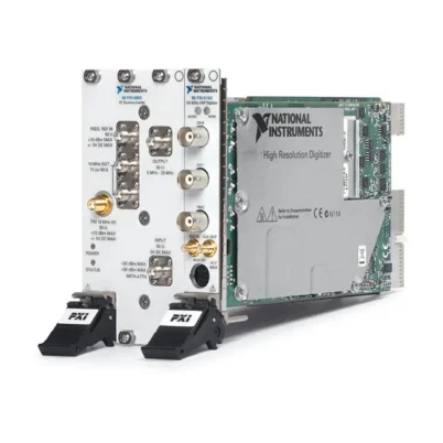
For RF generation, CH 0 can be connected to a compatible RF upconverter such as the PXI-5610. The waveform generator produces the modulated IF signal while the upconverter translates it to the required RF carrier frequency.
Triggering and Marker Events
The PXIe-5442 supports immediate, software, front-panel and PXI backplane triggering. Single, continuous, stepped and burst generation modes allow the waveform to respond to different test-sequence requirements.
Marker events can be placed at defined positions within waveform segments and routed to PFI or PXI trigger lines. Marker signals can trigger a digitizer, coordinate a DUT action or control an external switching system.
External and PXI Clocking
The CLK IN connector accepts an external sample clock or PLL reference. The module can also use the PXI Star trigger and PXI trigger lines as applicable sample-clock sources.
The PLL can lock to PXI_CLK10 or an external reference from 5 MHz to 20 MHz. Using a common reference clock helps maintain frequency and phase relationships between instruments.
NI-TClk Synchronization
The PXIe-5442 is based on NI Synchronization and Memory Core technology and supports NI-TClk synchronization. Multiple compatible waveform generators and digitizers can be aligned within a PXI system.
NI-TClk is useful for creating phase-coherent multichannel generators and synchronized stimulus-response systems. Final skew depends on the chassis, clock source, trigger routing and delay configuration.
Onboard Self-Calibration
An onboard 24-bit ADC and precision voltage reference calibrate DC gain and offset. The software-initiated self-calibration process takes approximately 75 seconds.
NI specifies a two-year external-calibration interval and a 15-minute warm-up period. External calibration also characterizes the VCXO, voltage reference, output impedance, gain and offset.
Typical PXIe-5442 Applications
- Intermediate-frequency signal generation
- Digital communications testing
- I/Q waveform generation
- GSM, W-CDMA and QAM signal generation
- RF upconverter stimulus
- Receiver and transmitter testing
- Amplifier and filter characterization
- ADC and mixed-signal device testing
- Валидация электронного дизайна
- Automated production testing
- Испытания в аэрокосмической и оборонной промышленности
- Scientific research
- Phase-coherent multichannel generation
- Stimulus-response measurement systems
Communications Testing
The onboard digital upconverter can generate complex modulated IF signals from baseband I/Q waveform data. Engineers can configure interpolation, pulse shaping, carrier frequency, gain and offset without creating every DAC sample in software.
This architecture is suitable for evaluating communications receivers, filters, amplifiers and modulation-processing subsystems.
RF Vector Signal Generation
When combined with a compatible RF upconverter, the PXIe-5442 can form part of a modular PXI vector signal generator. The PXIe-5442 produces the baseband or IF waveform while the RF module provides carrier translation.
This modular approach allows the waveform generator, RF upconverter and measurement instruments to share PXI clocks and trigger resources.
Stimulus-Response Testing
The PXIe-5442 can be paired with a PXIe-5622 digitizer for synchronized stimulus-response testing. The generator applies a controlled waveform while the digitizer captures the DUT output.
Applications include filter response measurements, amplifier testing, communications research and automated electronic validation.
Production Test Systems
In production testing, software can download a waveform library to onboard memory and select the required signal for each test stage. Sequence and script modes reduce the need for repeated waveform transfers.
PXI triggers and marker outputs coordinate signal generation with digitizers, switches and the device under test, improving repeatability and throughput.
NI-FGEN Software Support
The PXIe-5442 is controlled through the NI-FGEN instrument driver. NI-FGEN provides functions for configuring standard functions, downloading arbitrary waveforms, creating sequences, executing scripts and controlling triggers.
The driver supports LabVIEW, LabWindows/CVI and compatible text-based programming environments. It can also be incorporated into automated TestStand sequences.
PXI Express Chassis Integration
The PXIe-5442 occupies one slot in a compatible 3U PXI Express chassis. The chassis supplies power, cooling, PXI_CLK10 and backplane trigger routing.
The module consumes approximately 28.3 W during typical operation, so adequate forced-air cooling is important. Do not obstruct chassis airflow or exceed the specified operating temperature.
PXIe-5442 Troubleshooting
The PXIe-5442 Is Not Detected
Confirm that the module is fully inserted into a compatible PXI Express slot. Check chassis power, controller communication and NI-FGEN installation, then inspect the system in NI Measurement & Automation Explorer.
No Signal Appears at CH 0
Verify that the output is enabled and waveform generation has started. Check whether the module is waiting for a start or script trigger and inspect the SMB cable and DUT connection.
The Output Amplitude Is Incorrect
Confirm that the programmed load impedance matches the actual termination. Check whether the Main or Direct output path is selected and verify the configured amplitude, attenuation and offset.
The Signal Contains Unexpected Spectral Images
Review the DAC and OSP interpolation settings. Enable the appropriate digital or analog filter and confirm that the waveform sample rate is suitable for the required output bandwidth.
The I/Q Signal Is Distorted
Check the I/Q sample rate, interpolation, NCO frequency, prefilter gain and pulse-shaping parameters. Make sure the processed signal does not exceed the permitted digital or analog output range.
The Module Does Not Lock to the External Clock
Verify the external-clock frequency, input amplitude, duty cycle and 50 Ω termination. Confirm whether CLK IN is configured as the sample clock or PLL reference-clock source.
A Waveform Sequence Stops Unexpectedly
Review the waveform allocation, script instructions, loop counts and trigger configuration. Confirm that sufficient onboard memory is available for both waveform data and sequence instructions.
Multiple Modules Are Not Synchronized
Verify that all instruments use the intended common reference and compatible NI-TClk configuration. Check the sample rate, start trigger, interpolation and clock-delay settings.
Self-Calibration Fails
Allow the module to warm up for at least 15 minutes, remove inappropriate external signals and confirm that NI-FGEN can communicate with the module before repeating self-calibration.
PXIe-5442 Comparison with Related Waveform Generators
| Модель | Primary Configuration | Best Suited For |
|---|---|---|
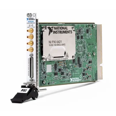
| PXI-5421 | 16 bit, 100 MS/s, 43 MHz, higher-voltage output | High-resolution arbitrary waveforms requiring up to 12 Vpk-pk into 50 Ω |
| PXIe-5442 | 16 bit, 100 MS/s, 43 MHz with 40 MHz OSP | I/Q, IF and digitally modulated waveform generation |
| PXIe-5450 | High-speed PXI Express I/Q signal generator | Applications requiring faster waveform generation |
| PXIe-5451 | Dual-channel high-speed arbitrary waveform generator | Wideband and phase-coherent two-channel generation |
| PXIe-5423 | Newer-generation 16-bit PXI Express waveform generator | Modern test systems requiring updated waveform architecture |
PXIe-5442 vs PXI-5421
Земля PXI-5421 and PXIe-5442 both provide 16-bit resolution, 100 MS/s sampling and 43 MHz bandwidth. The PXI-5421 provides a high-gain output path capable of 12 Vpk-pk into 50 Ω.
The PXIe-5442 provides a lower maximum output voltage but adds PXI Express connectivity and onboard signal processing with digital upconversion. Choose the PXIe-5442 for I/Q and communications signals, or the PXI-5421 when higher analog output voltage is required.
PXIe-5442 vs PXIe-5451
Земля PXIe-5451 provides two output channels and substantially higher sample-rate and bandwidth capability. It is better suited to wideband I/Q, quadrature and phase-coherent dual-channel applications.
The PXIe-5442 is appropriate when a single 43 MHz output channel, deep memory and 40 MHz onboard signal-processing bandwidth meet the application requirements.
Selecting the Right Memory Configuration
Choose the 32 MB PXIe-5442 for standard functions, short arbitrary records and waveform sequences that use extensive looping. Select the 256 MB version when longer nonrepeating waveforms are required.
The 512 MB version provides the longest onboard waveform duration and is recommended for complex communications patterns, extended I/Q sequences and applications that store several large waveforms simultaneously.
Recommended Related Products
- PXI-5421 16-Bit Arbitrary Waveform Generator
- PXIe-5450 I/Q Signal Generator
- PXIe-5451 Dual-Channel Arbitrary Waveform Generator
- PXIe-5622 High-Speed Digitizer
- PXI-5650 RF Signal Generator
- PXI-5651 RF Signal Generator
- PXIe-5672 Vector Signal Generator
- View More NI PXI and PXI Express Modules
Why Choose the PXIe-5442?
- Provides 16-bit arbitrary waveform generation
- Supports sampling rates up to 100 MS/s
- Offers greater than 43 MHz analog bandwidth
- Includes 40 MHz complex onboard processing bandwidth
- Generates real and complex I/Q waveforms
- Provides programmable digital upconversion
- Supports pulse-shaping and interpolation filters
- Offers as much as 512 MB of onboard memory
- Supports arbitrary sequences, scripts and waveform looping
- Provides extensive trigger and marker routing
- Supports external clocks, PXI_CLK10 and NI-TClk
- Integrates with NI-FGEN and PXI automated test systems
Frequently Asked Questions
What Is the PXIe-5442?
The PXIe-5442 is a single-channel, 16-bit PXI Express arbitrary waveform generator with a 100 MS/s sampling rate, 43 MHz bandwidth and onboard signal processing.
How Many Output Channels Does the PXIe-5442 Have?
The PXIe-5442 provides one analog output channel through the CH 0 SMB connector.
What Is the Maximum Output Amplitude?
The Main path provides up to 2 Vpk-pk into 50 Ω, approximately 3.81 Vpk-pk into 1 kΩ or 4 Vpk-pk into an open load.
What Is the Maximum Output Frequency?
The module generates sine and user-defined waveforms up to 43 MHz, square waves up to 25 MHz and triangle or ramp waveforms up to 5 MHz.
What Is Onboard Signal Processing?
Onboard signal processing performs operations such as interpolation, filtering, gain adjustment, offset adjustment and digital I/Q frequency translation inside the waveform generator.
Can the PXIe-5442 Generate I/Q Signals?
Yes. It supports real and complex I/Q processing with up to 40 MHz of complex bandwidth under the applicable sample-rate configuration.
What Memory Options Are Available?
The PXIe-5442 was offered with 32 MB, 256 MB or 512 MB of onboard waveform memory.
Can Multiple PXIe-5442 Modules Be Synchronized?
Yes. The module supports NI-TClk, PXI_CLK10, PXI trigger lines and external clocking for synchronized waveform generation.
Which Software Controls the PXIe-5442?
The PXIe-5442 is controlled through NI-FGEN and can be integrated with LabVIEW, LabWindows/CVI, TestStand and supported text-based programming environments.
What Are the PXIe-5442 Part Numbers?
The main part numbers are 780109-01 for 32 MB, 780109-02 for 256 MB and 780109-03 for 512 MB.
Request a Quote for the PXIe-5442
Contact us for current availability, condition, lead time and project pricing for the NI PXIe-5442 100 MS/s 16-Bit PXI Express Arbitrary Waveform Generator. Please provide the required memory size or complete part number so we can identify the correct 32 MB, 256 MB or 512 MB configuration.















