






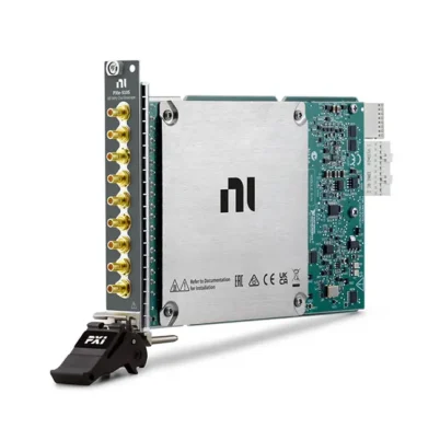
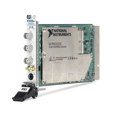
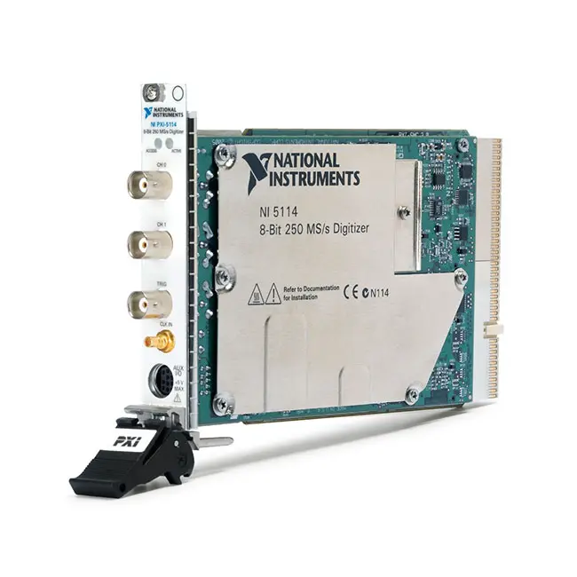
PXI-5114 2-Channel 125 MHz 250 MS/s PXI Oscilloscope
Земля NI PXI-5114 is a two-channel high-speed PXI oscilloscope and waveform digitizer designed for automated electronic testing, scientific measurements, communications testing and aerospace or defense applications. It provides two simultaneously sampled input channels, 8-bit vertical resolution, 125 MHz analog bandwidth and a real-time sampling rate of 250 MS/s per channel.
For repetitive signals, random-interleaved sampling increases the effective sampling rate to as much as 5 GS/s. The PXI-5114 also provides selectable 50 Ω or 1 MΩ input impedance, input ranges from 40 mVpp to 40 Vpp, adjustable vertical offset, advanced triggering and as much as 256 MB of onboard memory per channel.
Key Features of the PXI-5114
- Two simultaneously sampled analog input channels
- 8-bit vertical resolution
- 250 MS/s real-time sampling rate per channel
- Up to 5 GS/s random-interleaved sampling for repetitive signals
- 125 MHz analog input bandwidth
- Software-selectable 20 MHz noise filter
- Input ranges from 40 mVpp to 40 Vpp
- 50 Ω or 1 MΩ software-selectable input impedance
- AC, DC and ground input coupling options
- Programmable vertical offset
- 8 MB, 64 MB or 256 MB memory per channel
- Pretrigger and post-trigger acquisition
- Multiple-record waveform capture
- Edge, window, hysteresis, video and digital triggering
- Hardware trigger rearming
- High-resolution waveform timestamps
- External clock and reference-clock support
- PXI trigger and synchronization support
- NI-TClk multimodule synchronization
- Built-in self-calibration
- NI-SCOPE software support
PXI-5114 Technical Specifications
| Product Model | PXI-5114 |
|---|---|
| Product Type | PXI oscilloscope and high-speed digitizer |
| Analog Input Channels | 2, simultaneously sampled |
| Vertical Resolution | 8 bits |
| Maximum Real-Time Sample Rate | 250 MS/s per channel |
| Maximum Random-Interleaved Sample Rate | 5 GS/s for repetitive signals |
| Maximum Analog Bandwidth | 125 MHz |
| Bandwidth-Limit Filter | Software-selectable 20 MHz noise filter |
| Input Type | Referenced single-ended |
| Input Impedance | 50 Ω or 1 MΩ |
| 1 MΩ Input Capacitance | Approximately 26 pF |
| 50 Ω Input Ranges | 40 mVpp, 100 mVpp, 200 mVpp, 400 mVpp, 1 Vpp, 2 Vpp, 4 Vpp and 10 Vpp |
| 1 MΩ Input Ranges | 40 mVpp, 100 mVpp, 200 mVpp, 400 mVpp, 1 Vpp, 2 Vpp, 4 Vpp, 10 Vpp, 20 Vpp and 40 Vpp |
| 1 MΩ Input Coupling | AC, DC or ground |
| 50 Ω Input Coupling | DC or ground |
| Maximum 50 Ω Input | 7 Vrms with peak voltage not exceeding 10 V |
| Maximum 1 MΩ Input | Peak voltage not exceeding 35 V |
| Onboard Memory Options | 8 MB, 64 MB or 256 MB per channel |
| Trigger Types | Edge, window, hysteresis, video, digital and software |
| Trigger Sources | Analog channels, front-panel trigger, PXI trigger lines and software |
| Timestamp Resolution | High-resolution timestamping for trigger and acquisition events |
| Internal Sample Clock | 250 MHz |
| External Sample Clock | Supported from 50 MHz to 250 MHz |
| Reference Clock Sources | PXI 10 MHz backplane clock or front-panel external reference |
| Front-Panel Analog Connectors | 2 × BNC |
| External Trigger Connector | 1 × BNC |
| External Clock Connector | 1 × SMB |
| Self-Calibration | Gain, offset, attenuator and timing calibration |
| External Calibration Interval | 2 years |
| Software Driver | NI-SCOPE |
| Шинный интерфейс | PXI; compatible with supported PXI Express hybrid slots |
| Module Format | 3U, one-slot PXI module |
| Operating Temperature | 0°C to 55°C |
| Operating Humidity | 10% to 90%, noncondensing |
| Maximum Operating Altitude | 2,000 m |
PXI-5114 Part Numbers and Memory Options
| Product Configuration | Part Number | Onboard Memory |
|---|---|---|
| PXI-5114 Standard Memory | 779466-01 | 8 MB per channel |
| PXI-5114 Extended Memory | 779466-02 | 64 MB per channel |
| PXI-5114 Maximum Memory | 779466-03 | 256 MB per channel |
| 50 Ω BNC Cable | Configuration dependent | Coaxial cable for terminated high-frequency measurements |
| Passive Oscilloscope Probe | Configuration dependent | Probe for high-impedance measurements through the 1 MΩ input path |
| External Clock Cable | Configuration dependent | SMB cable for sample-clock or reference-clock connections |
The PXI-5114 memory is specified per channel rather than shared between both enabled channels. Select the memory option according to the required record length, sampling rate, number of records and duration of the event being captured.
Two Simultaneously Sampled Inputs
The PXI-5114 uses separate sampling paths for its two analog input channels. Both signals are digitized simultaneously, preserving the timing and phase relationship between the channels.
This capability is important for measuring input and output signals, comparing two related waveforms, calculating transfer functions and evaluating timing differences between circuits.
250 MS/s Real-Time Sampling
Each channel samples at up to 250 MS/s in real time, providing a sample interval of 4 ns. Real-time sampling captures each waveform from a single acquisition without reconstructing it from multiple repetitions.
This mode is appropriate for nonrepetitive transients, intermittent faults, pulses, modulation events and startup waveforms that may not occur in exactly the same form again.
5 GS/s Random-Interleaved Sampling
For stable repetitive signals, the PXI-5114 supports random-interleaved sampling at an effective rate of up to 5 GS/s. The instrument acquires many repetitions with different timing offsets and combines them into a higher-density waveform.
Random-interleaved sampling is not suitable for single-shot or changing signals because it assumes that successive waveform repetitions are substantially identical.
125 MHz Analog Bandwidth
The 125 MHz input bandwidth supports high-speed digital signals, electronic pulses, communications waveforms and general automated oscilloscope measurements.
System bandwidth is also affected by the probe, cable, fixture, termination and signal source. Use a measurement path with adequate bandwidth and controlled impedance when capturing fast edges.
8-Bit Vertical Resolution
The 8-bit ADC provides 256 theoretical amplitude levels across the selected input range. It is optimized for high-speed waveform capture and timing analysis rather than very-low-noise precision DC measurements.
Selecting the smallest range that safely contains the waveform improves amplitude resolution. Include overshoot and unexpected transient peaks when choosing the range.
Wide Input-Range Selection
The 1 MΩ signal path provides ten input ranges from 40 mVpp to 40 Vpp. The 50 Ω path offers eight ranges from 40 mVpp to 10 Vpp.
Each channel can use a different range. This allows the module to acquire signals with significantly different amplitudes during the same synchronized measurement.
50 Ω Input Impedance
The 50 Ω path is intended for impedance-matched signal sources and high-frequency coaxial systems. Proper termination reduces signal reflections and improves waveform fidelity.
When the input is configured for 50 Ω, observe the lower maximum input limits carefully. A high-voltage signal can dissipate excessive power in the internal termination and permanently damage the module.
1 MΩ Input Impedance
The 1 MΩ input path reduces loading on high-impedance circuits and supports conventional 10:1 oscilloscope probes. Its approximately 26 pF input capacitance should be included when evaluating high-frequency loading.
Use a correctly compensated probe and enter its attenuation factor in NI-SCOPE so displayed measurements represent the actual signal at the probe tip.
AC, DC and Ground Coupling
The 1 MΩ input path supports AC, DC and ground coupling. DC coupling preserves the complete signal, while AC coupling rejects the DC component and is useful for viewing ripple or noise on a DC supply.
Ground coupling disconnects the external signal from the internal measurement path and provides a reference for evaluating the oscilloscope baseline. The 50 Ω path supports DC and ground coupling.
Programmable Vertical Offset
Vertical offset moves the selected input range around a nonzero DC level. This allows the ADC to resolve a small time-varying signal riding on a larger DC voltage without increasing the full-scale range unnecessarily.
The available offset depends on input impedance and range. The combined input signal and programmed offset must remain within the instrument’s maximum input limits.
20 MHz Noise Filter
A software-selectable 20 MHz noise filter limits the analog signal-path bandwidth. It can reduce high-frequency noise when the information of interest is below 20 MHz.
Disable the filter when the application requires the full 125 MHz bandwidth or when fast pulse edges and higher-frequency components must be preserved.
Deep Per-Channel Memory
The PXI-5114 is available with 8 MB, 64 MB or 256 MB of memory for each channel. Deep memory allows long waveform records to be captured at high sampling rates.
The 256 MB version can store approximately 256 million 8-bit samples per channel before considering record-allocation overhead. This supports long transient captures and large multirecord acquisitions.
Multiple-Record Acquisition
Multiple-record mode captures a series of short triggered waveform segments without recording the inactive time between events. Hardware trigger rearming allows the module to prepare rapidly for the next event.
This method is useful for pulse trains, serial communications, radar or sonar events, switching cycles and other applications where important activity occurs in separated bursts.
Pretrigger and Post-Trigger Capture
Pretrigger acquisition stores waveform data from before the trigger event. Post-trigger acquisition records the signal after the event, and the trigger position can be adjusted according to the required analysis window.
Pretrigger information is especially valuable when diagnosing intermittent faults because it shows the conditions that led to the triggering event.
Edge Triggering
Edge triggering begins an acquisition when the selected signal crosses a defined voltage level in the chosen direction. It is the standard trigger mode for clock signals, pulses and repetitive electronic waveforms.
Trigger coupling, level, slope and holdoff should be configured according to the characteristics of the source signal.
Window and Hysteresis Triggering
Window triggering detects when a signal enters or leaves a selected voltage band. It is useful for identifying overvoltage, undervoltage and out-of-tolerance events.
Hysteresis triggering adds separate thresholds around the trigger level, reducing false triggers when noise is present near the transition point.
Video Triggering
The PXI-5114 supports video triggering, including formats used in automated video-electronics testing. It can isolate specific video events for waveform inspection and measurement.
Video trigger compatibility depends on the selected format, standard and NI-SCOPE software configuration.
External Clocking
The module can operate from its internal 250 MHz sampling clock or accept supported external sample clocks from 50 MHz to 250 MHz. External clocking allows acquisition timing to follow the device under test or a system timing source.
The sample clock should meet the instrument’s amplitude, duty-cycle, jitter and frequency requirements to maintain specified acquisition performance.
PXI Reference-Clock Synchronization
The internal timing system can phase lock to the PXI 10 MHz backplane reference clock. A supported external reference clock can also be connected through the front panel.
Reference-clock synchronization helps multiple digitizers, signal generators and digital instruments maintain a common frequency reference within an automated system.
NI-TClk Multimodule Synchronization
NI-TClk technology coordinates supported PXI instruments so their sample clocks and trigger events align precisely. Multiple PXI-5114 modules can be combined to create systems with more than two phase-coherent channels.
NI-TClk is also useful in mixed-signal systems combining digitizers with arbitrary waveform generators or digital waveform instruments.
Built-In Self-Calibration
Software-controlled self-calibration corrects gain, offset, compensated 1 MΩ attenuator and timing behavior according to the module’s current operating temperature.
Self-calibration helps maintain performance between external calibration services but does not replace traceable external calibration. NI specifies a two-year external calibration interval.
Communications Testing
The PXI-5114 can acquire baseband and intermediate-frequency communications signals within its analog bandwidth. Its 50 Ω input path, external clocking and deep memory support waveform-quality and modulation-related analysis.
Raw waveform data can be processed in software to calculate spectral content, pulse parameters, timing characteristics and application-specific measurements.
Aerospace and Defense Testing
The module can capture radar pulses, avionics signals, control-system transients and other electronic events in automated aerospace and defense test systems.
Multiple-record acquisition is particularly useful when many short events must be captured with accurate timing information while minimizing unnecessary data between pulses.
Consumer Electronics Testing
The wide input-range selection and high sampling rate make the PXI-5114 suitable for testing clocks, power rails, video circuits, control signals and other consumer electronic interfaces.
Production applications can use NI-SCOPE measurements to calculate amplitude, frequency, rise time, pulse width and other waveform parameters automatically.
Scientific Measurements
Researchers can use the PXI-5114 to acquire detector outputs, laser pulses, ultrasonic signals and fast transient events. Deep memory supports extended recording periods at high sample rates.
Hardware synchronization allows the acquisition to be coordinated with experimental stimulus sources, motion systems and other PXI instruments.
NI-SCOPE Software Support
The PXI-5114 is controlled through the NI-SCOPE instrument driver. NI-SCOPE provides channel, sampling, trigger, clock, memory and synchronization configuration through a consistent programming interface.
The driver includes waveform-fetching functions and more than 50 built-in measurements. It supports LabVIEW, LabWindows/CVI, Measurement Studio and compatible C, C++ and .NET development environments.
Typical PXI-5114 Applications
- Automated oscilloscope measurements
- Electronic production testing
- High-speed circuit validation
- Communications waveform acquisition
- Pulse and transient analysis
- Radar and sonar testing
- Video-electronics testing
- Aerospace and defense systems
- Scientific research
- Ultrasonic measurements
- Power-supply transient testing
- Consumer electronics validation
- Multiple-record event capture
- Phase-coherent multichannel acquisition
- Mixed-signal PXI test systems
PXI-5114 Troubleshooting
The PXI-5114 is not detected in NI MAX
Confirm that the module is fully installed in a compatible PXI or PXI Express hybrid peripheral slot. Check chassis power, controller communication and NI-SCOPE installation, then restart NI Measurement & Automation Explorer.
The acquired waveform is clipped
Select a larger input range or adjust the vertical offset. Confirm that the total signal, including DC level, noise and overshoot, remains within the selected range and maximum input limits.
The measured amplitude is lower than expected
Check the source and input termination. A source calibrated for a 50 Ω load may produce approximately twice its stated voltage when connected to a 1 MΩ input.
The 50 Ω input becomes disconnected
The internal thermal protection may activate after an overload. Remove the signal immediately, verify its voltage and allow the termination to cool. Persistent overload can damage the module.
High-frequency waveforms contain reflections
Use 50 Ω coaxial cable, proper termination and short signal paths. Avoid adapters, unterminated branches and fixture traces that introduce impedance discontinuities.
The waveform contains excessive noise
Select the smallest appropriate range and enable the 20 MHz noise filter if higher-frequency content is unnecessary. Check grounding, shielding and probe compensation.
Random-interleaved sampling produces incorrect results
Use RIS only for stable repetitive signals. Select 250 MS/s real-time sampling for nonrepetitive, modulated or time-varying waveforms.
The trigger is unstable
Review the trigger source, level, slope, coupling and hysteresis. Ensure that the signal crosses the selected threshold consistently and remains within the trigger-input limits.
Multiple modules are not aligned
Confirm that the modules use a shared reference clock and trigger path. Configure NI-TClk synchronization and verify the selected synchronization group and clock master.
PXI-5114 Comparison with Similar PXI Oscilloscopes
| Модель | Primary Configuration | Best Suited For |
|---|---|---|
| ПХИ-5105 | 8 channels, 12-bit, 60 MS/s, 60 MHz | High-channel-count simultaneous waveform acquisition |
| PXI-5114 | 2 channels, 8-bit, 250 MS/s, 125 MHz | High-speed general-purpose waveform and transient testing |
| PXI-5122 | 2 channels, 14-bit, 100 MS/s, 100 MHz | Higher-resolution waveform measurements |
| PXI-5124 | 2 channels, 12-bit, 200 MS/s, 150 MHz | Balanced bandwidth, sampling speed and vertical resolution |
| PXIe-5114 | 2 channels, 8-bit, 250 MS/s, 125 MHz, PXI Express | Equivalent measurement capability in PXI Express systems |
| PXIe-5160 | 2 channels, 10-bit, 2.5 GS/s, 500 MHz | Higher-speed and wider-bandwidth PXI Express measurements |
PXI-5114 vs PXI-5105
The PXI-5114 provides two channels, 250 MS/s real-time sampling and 125 MHz bandwidth. The ПХИ-5105 provides eight channels and 12-bit resolution but has a lower maximum sampling rate of 60 MS/s and 60 MHz bandwidth.
Select the PXI-5114 for faster two-channel measurements. Choose the PXI-5105 when simultaneous channel density and improved vertical resolution are more important.
PXI-5114 vs PXI-5122
The PXI-5114 offers a higher real-time sampling rate of 250 MS/s and 125 MHz bandwidth with 8-bit resolution. The PXI-5122 provides 14-bit resolution, 100 MS/s sampling and approximately 100 MHz bandwidth.
Choose the PXI-5114 for faster transient capture and timing analysis. Select the PXI-5122 when amplitude resolution, dynamic range and measurement fidelity are higher priorities.
PXI-5114 vs PXI-5124
The PXI-5124 provides 12-bit resolution, 200 MS/s sampling and approximately 150 MHz bandwidth. The PXI-5114 provides a slightly higher 250 MS/s sampling rate but lower 8-bit resolution and 125 MHz bandwidth.
Select the PXI-5114 for applications prioritizing real-time sampling rate and deep multirecord capture. Choose the PXI-5124 for greater vertical resolution and bandwidth.
PXI-5114 vs PXIe-5114
The PXI-5114 and PXIe-5114 provide similar two-channel, 8-bit, 250 MS/s and 125 MHz measurement capability. Their primary difference is the backplane interface.
Choose the PXI-5114 for existing standard PXI systems or compatible hybrid slots. Select the PXIe-5114 when a native PXI Express interface is required.
Recommended Related Products
- PXI-5105 8-Channel 60 MHz Oscilloscope
- PXIe-5114 2-Channel 125 MHz Oscilloscope
- PXI-5122 14-Bit 100 MS/s Digitizer
- PXI-5124 12-Bit 200 MS/s Digitizer
- PXIe-5160 2.5 GS/s PXI Express Oscilloscope
- PXIe-1078 9-Slot PXI Express Chassis
- PXIe-1082 8-Slot PXI Express Chassis
- View More NI PXI Oscilloscopes and Digitizers
Selecting the Right PXI Oscilloscope
Choose the PXI-5114 when the test system requires two synchronized channels, 125 MHz bandwidth, 250 MS/s real-time sampling and deep acquisition memory. It is suitable for high-speed waveform capture, pulse testing and automated electronic validation.
Select the PXI-5105 when additional channel density is required. Consider the PXI-5122 or PXI-5124 when higher vertical resolution is more important than maximum real-time sampling speed.
Choose the 8 MB version for short waveform records, the 64 MB version for medium-length acquisitions and the 256 MB version for long records or large multirecord tests.
Why Choose the PXI-5114?
- Provides two simultaneously sampled input channels
- Offers 250 MS/s real-time sampling per channel
- Supports 5 GS/s RIS for repetitive waveforms
- Provides 125 MHz analog bandwidth
- Supports input ranges from 40 mVpp to 40 Vpp
- Offers selectable 50 Ω and 1 MΩ input impedance
- Provides up to 256 MB of memory per channel
- Supports advanced analog, video and digital triggering
- Includes self-calibration and NI-TClk synchronization
- Integrates with NI-SCOPE and LabVIEW
Frequently Asked Questions
What is the PXI-5114?
The PXI-5114 is a two-channel, 8-bit PXI oscilloscope with 125 MHz bandwidth, 250 MS/s real-time sampling and up to 256 MB of onboard memory per channel.
What is the maximum real-time sampling rate?
The maximum real-time sampling rate is 250 MS/s on each of the two channels.
Does the PXI-5114 support equivalent-time sampling?
Yes. It supports random-interleaved sampling at effective rates up to 5 GS/s for stable repetitive signals.
What is the analog bandwidth?
The maximum analog input bandwidth is 125 MHz. A software-selectable 20 MHz noise filter is also available.
What input ranges are available?
The module provides ranges from 40 mVpp to 40 Vpp on the 1 MΩ path and from 40 mVpp to 10 Vpp on the 50 Ω path.
Which input impedances are supported?
Each channel can be configured independently for 50 Ω or 1 MΩ input impedance.
Which PXI-5114 part number has 8 MB of memory?
Part number 779466-01 provides 8 MB of onboard memory per channel.
Which PXI-5114 part number has 64 MB of memory?
Part number 779466-02 provides 64 MB of onboard memory per channel.
Which PXI-5114 part number has 256 MB of memory?
Part number 779466-03 provides 256 MB of onboard memory per channel.
Does the PXI-5114 support video triggering?
Yes. The PXI-5114 supports video triggering in addition to edge, window, hysteresis, digital and software triggering.
Can multiple PXI-5114 modules be synchronized?
Yes. Multiple supported modules can share reference clocks and trigger signals using PXI resources and NI-TClk synchronization.
Which driver controls the PXI-5114?
The PXI-5114 is controlled through the NI-SCOPE instrument driver.
Can the PXI-5114 operate in a PXI Express chassis?
Yes. The module can be installed in a compatible PXI Express hybrid peripheral slot, but not in a PXI Express-only peripheral slot without the hybrid connector.
Request a Quote for the PXI-5114
Contact us for current availability, memory configuration, product condition, calibration status, lead time and project pricing for the PXI-5114 2-Channel 125 MHz 250 MS/s PXI Oscilloscope. We can also help identify compatible probes, BNC cables, PXI chassis, controllers and related high-speed digitizers.















