




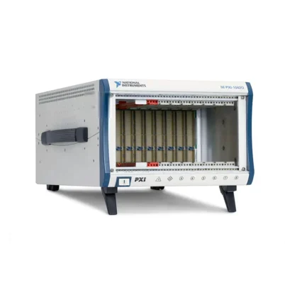

PXIe-1086DC 18-Slot Redundant DC PXI Express Chassis
Земля NI PXIe-1086DC is an 18-slot PXI Express chassis designed for high-availability automated test, measurement and control systems. It provides one system-controller slot, 16 hybrid peripheral slots and one dedicated PXI Express system timing slot.
The PXIe-1086DC delivers up to 12 GB/s maximum system bandwidth and 855 W of total usable backplane power. Its power system accepts 210 VDC to 300 VDC input and can also operate from compatible 90 VAC to 264 VAC sources, making it suitable for industrial, transportation and specialized DC-powered installations.
Hot-swappable redundant power supplies and front-accessible redundant cooling fans help reduce system downtime. Integrated monitoring tracks supply health, backplane voltages, intake temperature, fan health and fan speed, while chassis status indicators provide visible fault information.
Key Features of the PXIe-1086DC
- 18-slot 3U PXI Express chassis
- One dedicated system-controller slot
- 16 hybrid peripheral slots
- One PXI Express system timing slot
- Up to 12 GB/s maximum system bandwidth
- 855 W maximum total usable power
- 210 VDC to 300 VDC operating input range
- 90 VAC to 264 VAC operating input range
- Hot-swappable redundant power supplies
- Power-supply replacement in less than one minute
- Hot-swappable front-accessible redundant fan modules
- Six 150 CFM fans arranged in three dual-fan assemblies
- 38.25 W maximum peripheral-slot dissipation
- 140 W maximum system-controller-slot dissipation
- External 10 MHz reference input and output
- PXI star and PXI Express differential star triggering
- Power, voltage, temperature and fan monitoring
- Front-access power architecture
- Compatible with benchtop and rack-mounted systems
PXIe-1086DC Technical Specifications
| Product Model | PXIe-1086DC |
|---|---|
| Part Number | 787137-01 |
| Product Type | Redundant DC-powered PXI Express chassis |
| Chassis Format | 3U, 18-slot PXI Express chassis |
| Total Physical Slots | 18 |
| System-Controller Slots | 1 |
| Hybrid Peripheral Slots | 16 |
| PXI Express System Timing Slots | 1 |
| Maximum System Bandwidth | Up to 12 GB/s |
| Maximum Total Usable Power | 855 W |
| Maximum Combined ±12 V Power with One Supply | 588 W |
| Maximum Controller-Slot Dissipation | 140 W |
| Maximum Peripheral-Slot Dissipation | 38.25 W |
| Power-Supply Architecture | Hot-swappable redundant DC power supplies |
| Rated DC Input | 210 VDC to 300 VDC, 3.5 A to 6 A |
| DC Operating Voltage Range | 210 VDC to 300 VDC |
| Rated AC Input | 100 VAC to 240 VAC, 12 A to 6 A |
| AC Operating Voltage Range | 90 VAC to 264 VAC |
| Nominal AC Frequency | 50/60 Hz |
| AC Operating Frequency Range | 47 Hz to 63 Hz |
| Typical Power-Supply Efficiency | 70% |
| Maximum +3.3 V Current | 50 A with one supply; 60 A with two supplies |
| Maximum +5 V Current | 40 A with one supply; 49 A with two supplies |
| Maximum +12 V Current | 50 A with one supply; 62 A with two supplies |
| Maximum −12 V Current | 4 A |
| Maximum +5 V Auxiliary Current | 1.5 A |
| Power-Supply Replacement Time | Less than one minute |
| Cooling System | Forced-air positive-pressurization cooling |
| Module Cooling Fans | Six 150 CFM fans in three dual-stacked assemblies |
| Fan-Speed Selection | Auto or High |
| Module Airflow Direction | Bottom to top |
| Module Air Intake | Bottom of chassis |
| Module Air Exhaust | Top of chassis |
| System Timing Slot | Да |
| External Clocking | Да |
| Integrated External Trigger Access | No |
| Onboard Clock Type | VCXO |
| PXI_CLK10 Accuracy | ±25 ppm maximum |
| PXI_CLK10 Slot-to-Slot Skew | 500 ps maximum |
| PXIe_CLK100 Accuracy | ±25 ppm maximum |
| PXIe_CLK100 Slot-to-Slot Skew | 100 ps maximum |
| PXI Star Trigger Slot-to-Slot Skew | 250 ps maximum |
| Differential Star Trigger Slot-to-Slot Skew | 150 ps maximum |
| Differential Star Trigger Skew | 25 ps maximum |
| External Reference Input | 10 MHz ±100 ppm through front-panel SMA |
| External Reference Output | 10 MHz through front-panel SMA |
| Operating Temperature | 0°C to 50°C |
| Operating Humidity | 10% to 90%, noncondensing |
| Storage Temperature | −40°C to 71°C |
| Storage Humidity | 5% to 95%, noncondensing |
| Maximum Operating Altitude | 4,600 m at 25°C with High fan mode |
| Operational Shock | 30 g peak, half-sine, 11 ms pulse |
| Operational Random Vibration | 5 Hz to 500 Hz, 0.3 grms |
| Auto-Fan Sound Pressure | 57.0 dBA at up to approximately 30°C ambient |
| High-Fan Sound Pressure | 69.0 dBA |
| Dimensions | 268.7 × 467.1 × 476.5 mm |
| Weight with Two Power Supplies | 17.1 kg |
| Weight with One Power Supply | 14.3 kg |
| Intended Environment | Indoor use |
PXIe-1086DC Part Number and Accessories
| Item | Part Number | Описание |
|---|---|---|
| PXIe-1086DC | 787137-01 | 18-slot, 12 GB/s redundant DC PXI Express chassis with front power access |
| Replacement Power Supply | 782106-01 | Replacement or additional power supply for the PXIe-1086DC |
| Replacement Fan Assembly | 782107-01 | Hot-swappable modular cooling-fan assembly |
| Power-Supply Filler Panel | 784057-01 | Required in the unused supply position for specified single-supply shock and vibration operation |
| Three-Meter Power Cord | Included | Power cable supplied with the standard chassis package |
| Single-Slot Filler Panels | Included | Seven single-slot PXI filler panels |
| Double-Slot Filler Panel | Included | One double-slot PXI filler panel |
| Quadruple-Slot Filler Panels | Included | Two quadruple-slot PXI filler panels |
| Mini-COMBICON Connector Plug | Included | Connector for supported chassis power-control functions |
| EMI Suppression Ferrite | Included | Ferrite supplied for compliant power-cable installation |
| Front Rack-Mount Kit | Configuration dependent | Optional brackets for front-facing rack installation |
| Rear Rack-Mount Kit | Configuration dependent | Optional rear support for compatible instrument cabinets |
The standard PXIe-1086DC package includes the chassis, seven single-slot filler panels, one double-slot filler panel, two quadruple-slot filler panels, a three-meter power cord, a Mini-COMBICON plug, an EMI suppression ferrite and safety documentation.
Verify the input-power architecture before ordering. The source, cable, connectors, disconnect device, overcurrent protection and grounding arrangement must be suitable for the intended AC or high-voltage DC supply.
18-Slot PXI Express Architecture
The PXIe-1086DC provides one system-controller slot and 17 peripheral positions. Sixteen peripheral positions use hybrid connectors, and the remaining position is a dedicated PXI Express system timing slot.
This capacity allows a single system to combine data acquisition, signal generation, switching, digital I/O, programmable power, RF measurement, FPGA processing and communication interfaces.
The controller position includes three adjacent system expansion slots. A four-slot embedded controller uses these positions, so controller width must be considered when calculating the remaining capacity.
Sixteen Hybrid Peripheral Slots
The 16 hybrid peripheral positions support compatible PXI Express modules and hybrid-compatible conventional PXI instruments. This provides greater flexibility when building or upgrading mixed-generation systems.
Existing PXI modules can be retained while newer PXI Express instruments are added for applications requiring higher-speed data transfer or FPGA processing.
Each module must be checked for connector, signaling-voltage, driver, operating-system, power and cooling compatibility. Never force an incompatible PXI connector into a hybrid slot.
Dedicated System Timing Slot
The dedicated PXI Express system timing slot provides specialized clocking and trigger resources for compatible timing and synchronization modules.
A timing module can distribute reference clocks and triggers among instruments, coordinate several chassis or synchronize the PXI system with external equipment.
This capability is valuable in phase-coherent acquisition, synchronized waveform generation, high-channel-count digitizer systems and hardware-in-the-loop testing.
12 GB/s System Bandwidth
The PXIe-1086DC provides up to 12 GB/s of aggregate system bandwidth between the controller and chassis backplane.
The available bandwidth is allocated according to the backplane topology and installed controller. Actual throughput also depends on each module’s PCI Express link, simultaneous transfers, storage performance and software processing.
For continuous acquisition, calculate the data rate from every digitizer, RF instrument and FPGA module. Lower-bandwidth switching and communication modules generally place less demand on the backplane.
High-Voltage DC Input
The defining feature of the PXIe-1086DC is its support for 210 VDC to 300 VDC input. This high-voltage DC range is intended for facilities and specialized systems where a regulated DC distribution bus is available.
The input is not designed for common low-voltage 12 V, 24 V or 48 V sources. Connecting a low-voltage DC supply will not provide the required operating voltage.
High-voltage DC installation must be completed by qualified personnel using correctly rated conductors, connectors, protection devices, grounding and disconnect hardware.
Compatible AC Input Operation
Although designated as a DC chassis, the PXIe-1086DC power supply also accepts 100 VAC to 240 VAC nominal input. Its guaranteed AC operating range is 90 VAC to 264 VAC at 47 Hz to 63 Hz.
This dual AC/DC input capability allows the same chassis to be deployed in high-voltage DC environments or operated from conventional laboratory AC power when required.
The power-cable and protection arrangement must be selected for the actual input source rather than the product name alone.
855 W Total Usable Power
The power system supplies up to 855 W of usable backplane power. This supports large configurations containing multiple acquisition, switching, RF and control modules.
Total wattage is only one part of the power calculation. With a single supply, the specified maximum currents include 50 A at +3.3 V, 40 A at +5 V and 50 A at +12 V. Dual supplies increase the available current on these rails, subject to the 855 W total limit.
The maximum combined power from the +12 V and −12 V rails with one power supply is 588 W. Verify the voltage-rail requirements of every installed module before operating the system.
Hot-Swappable Redundant Power Supplies
The PXIe-1086DC supports two redundant hot-swappable power supplies. When both are functional and the load remains within the supported redundancy budget, either supply can be removed without disconnecting system power.
This architecture reduces the risk that a single supply failure will interrupt an important production, qualification or monitoring process.
Redundancy requires the remaining supply to support the complete system load. A heavily loaded configuration can operate with two supplies but still exceed the capacity of one supply during a failure.
Fast Power-Supply Replacement
The specified mean time to repair for a power-supply shuttle is less than one minute. Captive screws and a collapsible handle allow a qualified technician to remove the supply from the chassis.
When rear access is restricted, the chassis power drawer can provide an alternative service path. Power-drawer removal has different safety requirements and may require complete AC or DC disconnection.
Always follow the service instructions for the exact operation being performed. Hot-swappable supplies do not make every part of the power drawer safe to remove while energized.
Single-Power-Supply Operation
The chassis can operate with one installed supply, but hardware redundancy is lost and the single-supply current limits apply.
A power-supply filler panel, part number 784057-01, must be installed in the empty bay to meet the documented operational shock and vibration specifications.
The filler panel also protects the unused bay and helps maintain the designed airflow path.
Redundant Front-Accessible Cooling Fans
Six 150 CFM fans are arranged as three columns of dual-stacked fans. The redundant design allows one fan assembly to be removed while the corresponding second fan continues operating.
The fan assemblies are accessible from the front of the chassis and are hot swappable under supported conditions. This reduces service time in racks where rear access is limited.
Never remove both fans from the same column. Removing both fans, or removing the remaining working fan in a column that already contains a failed unit, can cause the chassis to shut down.
Positive-Pressurization Cooling
Cooling air enters through the bottom and travels upward through the instrument slots before exhausting along the top of the chassis.
Positive pressurization directs air through the installed modules. The power supplies use integrated fans with intake at the rear and exhaust through the top.
Every unused instrument position must be covered with a filler panel. Open slots can allow air to bypass active modules and reduce cooling efficiency.
Cooling Clearance Requirements
Maintain at least 44.45 mm of clearance above and on both sides of the chassis. At least 76.20 mm of clearance is required behind it.
The bottom air intake and top exhaust must remain unobstructed. Nearby equipment should not discharge hot air directly into the chassis intake.
High-altitude operation up to 4,600 m requires the fan selector to be placed in High mode.
Chassis Health Monitoring
The PXIe-1086DC monitors power-supply health, backplane voltages, air-intake temperature, cooling-fan health and fan speed.
Status LEDs provide visible notification of detected failures. This helps maintenance personnel distinguish a supply problem from a cooling or temperature fault.
Monitoring information can be incorporated into preventive-maintenance procedures. Operators should define how the system will save data and place the DUT in a safe state when a serious fault occurs.
External 10 MHz Reference Input
A front-panel SMA connector accepts an external 10 MHz reference signal with a frequency tolerance of ±100 ppm. The supported input amplitude is 200 mVpp to 5 Vpp for a sine or square waveform.
The input impedance is 50 Ω. Use correctly terminated coaxial cabling to reduce reflections and clock-distribution errors.
An external reference can synchronize the PXI backplane with another chassis, laboratory reference or compatible instrument.
External 10 MHz Reference Output
The chassis provides a front-panel SMA 10 MHz reference output. Its specified amplitude is 1 Vpp into 50 Ω or 2 Vpp when unloaded.
The output has a 50 Ω nominal impedance and can be used to distribute the chassis reference to compatible external equipment.
Verify the destination impedance and avoid adding unsupported passive loads that could reduce the output amplitude.
Backplane Timing and Triggering
The PXIe-1086DC distributes PXI_CLK10, PXIe_CLK100 and PXIe_SYNC100 through the backplane. Both principal reference clocks have a maximum frequency accuracy of ±25 ppm.
PXI_CLK10 provides a maximum slot-to-slot skew of 500 ps. PXIe_CLK100 provides a maximum slot-to-slot skew of 100 ps.
The chassis also supports PXI star triggering and PXI Express differential star resources. Actual system synchronization depends on the timing module, peripheral instruments, routes, software and external cabling.
Remote Power Control
The front-panel four-pin terminal-block connection and power-mode switch support integration with compatible remote power-control systems.
This capability is useful in centralized test racks where several chassis and instruments must follow a coordinated startup or emergency-shutdown sequence.
The AC/DC input cable remains the main power disconnect. Do not locate the chassis where the input connector cannot be reached safely.
Rack-Mount System Integration
The chassis measures approximately 268.7 mm high, 467.1 mm wide and 476.5 mm deep. It weighs approximately 17.1 kg with two power supplies before controllers, modules and cables are added.
Optional front and rear rack-mount kits support installation in compatible instrument cabinets. The symmetrical chassis mounting holes allow different rack orientations.
Provide adequate mechanical support and use safe lifting procedures. Heavy cable bundles should be supported independently instead of hanging from module front panels.
PXIe-1086DC Applications
- High-availability automated test equipment
- DC-powered industrial test systems
- Transportation and mobile test platforms
- Aerospace and defense validation
- Continuous production functional testing
- High-channel-count data acquisition
- Automotive ECU and HIL testing
- RF and wireless-device validation
- Power-electronics testing
- Semiconductor characterization
- Long-duration reliability testing
- Synchronized multi-instrument measurement
High-Availability Production Testing
The redundant power and cooling systems make the PXIe-1086DC suitable for production lines where an unexpected shutdown can interrupt manufacturing and delay delivery.
Power supplies and fan assemblies can be replaced quickly, while chassis monitoring helps maintenance personnel identify the component requiring attention.
DC-Powered Industrial Installations
The high-voltage DC input allows the chassis to operate from compatible industrial DC distribution systems. This may reduce the need for an additional DC-to-AC conversion stage.
The available source must remain within the 210 VDC to 300 VDC operating range and provide sufficient current for the chassis configuration.
Aerospace and Defense Testing
Aerospace test systems can combine avionics communication interfaces, digitizers, FPGA modules, switches, signal generators and sensor-measurement hardware.
The system timing slot and external reference connections help coordinate instrumentation in synchronized validation environments.
Automotive ECU and HIL Validation
Vehicle interfaces, fault-insertion switches, real-time controllers, FPGA hardware and analog I/O modules can be combined for ECU hardware-in-the-loop testing.
Power and cooling redundancy are particularly useful for long regression sequences where a system interruption could require many hours of testing to be repeated.
High-Channel-Count Data Acquisition
The 17 peripheral positions can support multiple DAQ, temperature, strain, vibration and digitizer modules. A common chassis simplifies timing and communication between the instruments.
Continuous streaming must remain within the backplane, controller, memory and storage limitations of the complete system.
RF and Wireless Testing
Compatible RF generators, analyzers, digitizers and switching modules can be installed for wireless component and subsystem testing.
Applications transferring large RF data sets should calculate their combined throughput against the chassis’s 12 GB/s maximum bandwidth.
Reliability and Environmental Testing
The PXIe-1086DC can support long-duration qualification systems operating continuously for days or weeks. Redundant serviceable components help reduce the risk of losing progress because of a single supply or fan failure.
Test applications should still save data regularly and implement a controlled response for temperature, power or communication faults.
PXIe-1086DC Installation Workflow
Step 1: Confirm the Input-Power Source
Determine whether the system will operate from 210 VDC to 300 VDC or from 90 VAC to 264 VAC. Do not connect the chassis to a common 12 V, 24 V or 48 V DC source.
Verify Source Capacity
The input source must provide adequate voltage and current for the installed chassis configuration, including startup and worst-case module loading.
Verify Protection and Disconnect Hardware
Use appropriately rated conductors, overcurrent protection, grounding and a readily accessible disconnect method.
Step 2: Inspect the Chassis and Accessories
Check the chassis, power supplies, fans, power cord, filler panels, ferrite and terminal-block plug for damage. Confirm part number 787137-01.
Step 3: Prepare a Slot Map
List the controller, system timing module and peripheral instruments. Record module width, connector type, bandwidth, power and cooling requirements.
Reserve the dedicated timing slot for the synchronization module and account for any multi-slot controller or instrument.
Step 4: Calculate the Power Budget
Confirm that the configuration remains within the 855 W total power limit and the current ratings for each voltage rail.
For redundant operation, make sure one power supply can support the required system load if the second supply fails or is removed.
Step 5: Install the Chassis
Place the chassis on a stable bench or install it with compatible front and rear rack-mount hardware. Maintain the specified top, side and rear clearances.
Ensure that the bottom intake remains open after rack shelves, cable trays and neighboring equipment are installed.
Step 6: Connect Protective Ground
Connect the chassis only through the approved grounding and input-power arrangement. Qualified personnel should perform high-voltage DC wiring.
Install the supplied EMI suppression ferrite as directed by the chassis documentation.
Step 7: Power Off Before Installing Modules
Disconnect the input source and confirm that the chassis is de-energized. Follow antistatic precautions while handling the controller and peripheral modules.
Step 8: Install the System Controller
Insert the embedded controller or remote-control interface into the system slot. Align it with the guides, seat the backplane connectors fully and tighten the retaining screws.
Step 9: Install the Timing and Peripheral Modules
Install the timing module in the dedicated system timing slot. Place remaining instruments according to the prepared slot map.
Confirm that no peripheral module exceeds the 38.25 W dissipation limit.
Step 10: Install Filler Panels
Cover every unused instrument position with an appropriately sized filler panel. When only one supply is installed, fit power-supply filler panel 784057-01 in the empty bay.
Step 11: Connect Input Power
Connect both power supplies when redundant operation is required. Where the installation permits, design the upstream distribution so one failure does not remove power from both supplies.
Step 12: Power On and Verify Status
Turn on the chassis and check all supply, fan and temperature indicators. Confirm that no voltage or cooling fault is reported.
Step 13: Detect the Installed Hardware
Start the controller and use NI Measurement & Automation Explorer to verify the chassis and peripheral modules. Install the required drivers and complete the available self-tests.
Step 14: Test Redundancy Safely
After confirming that the load remains within single-supply capacity, follow the approved procedure to verify that either supply can support the system.
Do not test fan redundancy by removing both fans from the same vertical column.
PXIe-1086DC Troubleshooting
The Chassis Does Not Power On
Measure the input source and confirm that it falls within the specified DC or AC operating range. Check the power cable, disconnect device, fuses and front-panel power-control mode.
If remote power control is used, inspect the Mini-COMBICON wiring and confirm that an external inhibit signal is not preventing startup.
A 24 V or 48 V DC Supply Does Not Start the Chassis
The PXIe-1086DC requires 210 VDC to 300 VDC. Its DC input is not designed for common low-voltage industrial sources.
Use a correctly rated power-conversion system if only low-voltage DC is available.
One Power Supply Shows a Fault
Check its input connection, seating and status indicator. Confirm that the second supply is operating and can support the installed load.
Replace the failed supply with the compatible 782106-01 unit to restore redundancy.
The System Shuts Down When One Supply Is Removed
The remaining supply may not have input power, or the system load may exceed the single-supply current capacity.
Review each voltage rail and reduce the installed load before repeating the redundancy test.
A Fan Fault Is Reported
Identify the affected assembly using the status indicators. Inspect the air path and replace the defective fan with a compatible 782107-01 assembly.
Do not remove the second working fan in the same column, because the chassis can shut down when both fans in one column are absent.
The Chassis Reports Excessive Temperature
Check the bottom intake, top exhaust, filler panels and required installation clearances. Confirm that every fan operates and that the intake air remains within the specified temperature range.
Set the fan selector to High when required by altitude or environmental conditions.
An Installed PXI Module Is Not Detected
Power down the chassis and reseat the module. Confirm hybrid-slot compatibility and install the correct device driver.
Use NI MAX to rescan the system. Moving the module to another supported position can help distinguish a module problem from a slot issue.
Data Throughput Is Lower Than Expected
Review the controller link, chassis topology and combined data rate of all active modules. The 12 GB/s figure is an aggregate maximum rather than a guaranteed bandwidth for every slot.
CPU workload, memory use, DMA settings and storage performance can also limit sustained throughput.
External Clock Synchronization Does Not Work
Confirm that the external source is 10 MHz within ±100 ppm and has an amplitude between 200 mVpp and 5 Vpp.
Use 50 Ω cabling and verify the input/output routing, termination and timing-module configuration.
The Chassis Produces High Fan Noise
High fan mode produces substantially more acoustic noise than Auto mode. Increased speed may be required by temperature, altitude or the selected cooling configuration.
Do not reduce fan speed if doing so would violate the cooling requirements of the installed modules.
The Chassis Fails a Shock or Vibration Requirement
If only one power supply is installed, verify that filler panel 784057-01 is correctly fitted in the empty supply bay.
Also confirm that the chassis, rack hardware, modules and cables are properly secured.
PXIe-1086DC Comparison
| Функция | PXIe-1086DC | PXIe-1086 | PXIe-1085 | PXIe-1095 |
|---|---|---|---|---|
| Общее количество слотов | 18 | 18 | 18 | 18 |
| Hybrid Peripheral Slots | 16 | 16 | 16 | 5 |
| System Timing Slot | Да | Да | Да | Да |
| Maximum System Bandwidth | 12 GB/s | 12 GB/s | Up to 24 GB/s | 24 ГБ/с |
| Maximum Slot Dissipation or Cooling | 38.25 W | 38.25 W | 38 Вт | 82 Вт |
| Power Input | 210–300 VDC or 90–264 VAC | 90–264 VAC | AC | AC |
| Redundant Power and Cooling | Да | Да | No | Да |
| Primary Advantage | High-voltage DC input with high-availability hardware | Redundant architecture for conventional AC installations | Higher bandwidth with 16 hybrid positions | Higher bandwidth and per-slot cooling |
PXIe-1086DC vs PXIe-1086
Земля PXIe-1086 and PXIe-1086DC share an 18-slot layout, 16 hybrid slots, a system timing slot, 12 GB/s bandwidth, 855 W usable power and redundant serviceable hardware.
The principal difference is input power. The PXIe-1086DC accepts 210 VDC to 300 VDC and compatible AC input, while the PXIe-1086 is intended primarily for conventional AC operation.
The PXIe-1086DC also places its external 10 MHz reference connections on front-panel SMA connectors, whereas the standard PXIe-1086 uses its applicable chassis clocking arrangement.
PXIe-1086DC vs PXIe-1085
Земля PXIe-1085 provides up to 24 GB/s bandwidth and 16 hybrid peripheral slots but does not include the PXIe-1086DC redundant power and fan architecture.
Choose the PXIe-1085 when higher bandwidth is the primary requirement. Choose the PXIe-1086DC when high-voltage DC input and service availability are more important.
PXIe-1086DC vs PXIe-1095
Земля PXIe-1095 offers up to 24 GB/s system bandwidth and as much as 82 W of power and cooling per slot. It is designed for newer, higher-power PXI Express instruments.
The PXIe-1086DC provides more hybrid-compatible positions and supports high-voltage DC input. The appropriate chassis depends on legacy-module compatibility, power source, module cooling and bandwidth requirements.
Selecting the Right PXI Express Chassis
Choose the PXIe-1086DC when the system requires 18 slots, 16 hybrid positions, redundant hardware and operation from a 210 VDC to 300 VDC source.
Select the standard PXIe-1086 for similar high-availability systems using conventional AC power. Choose a 24 GB/s chassis when multiple high-speed instruments must stream large volumes of data simultaneously.
Why Choose the PXIe-1086DC?
- Accepts high-voltage DC and universal AC input
- Provides 16 flexible hybrid peripheral slots
- Supports up to 12 GB/s system bandwidth
- Delivers up to 855 W of usable backplane power
- Includes hot-swappable redundant power supplies
- Includes hot-swappable redundant cooling fans
- Supports rapid power-supply replacement
- Monitors power, voltage, temperature and fan health
- Includes a dedicated system timing slot
- Provides front-panel external 10 MHz reference connections
- Supports rack-mounted high-availability test systems
PXIe-1086DC Frequently Asked Questions
What is the PXIe-1086DC?
The PXIe-1086DC is an 18-slot redundant PXI Express chassis designed for high-availability test, measurement and control systems requiring compatible high-voltage DC power.
What is the PXIe-1086DC part number?
The standard NI part number is 787137-01.
How many peripheral slots does it provide?
It provides 17 peripheral positions: 16 hybrid slots and one dedicated PXI Express system timing slot.
What DC voltage does it require?
The supported DC operating range is 210 VDC to 300 VDC. It cannot operate directly from typical 12 V, 24 V or 48 V DC supplies.
Can the PXIe-1086DC operate from AC power?
Yes. The power supply also supports an AC operating range of 90 VAC to 264 VAC at 47 Hz to 63 Hz.
What is the maximum system bandwidth?
The chassis supports up to 12 GB/s of aggregate system bandwidth.
What is the maximum available power?
The PXIe-1086DC provides up to 855 W of total usable backplane power, subject to the individual voltage-rail limits.
Does it include redundant power supplies?
It supports dual hot-swappable redundant supplies. The system load must remain within the capacity of one supply if uninterrupted operation is required after a supply failure.
Can a power supply be replaced while operating?
Yes, when both supplies are installed and the remaining supply is operational and capable of carrying the complete load. Follow the official replacement procedure.
What is the replacement power-supply part number?
The compatible replacement power supply is 782106-01.
What is the replacement fan part number?
The compatible modular replacement fan assembly is 782107-01.
Can the chassis operate with one supply?
Yes, but redundancy is lost and single-supply current limits apply. Power-supply filler panel 784057-01 must be installed to meet the documented shock and vibration specifications.
What is the maximum peripheral-slot power?
The maximum permitted peripheral-slot dissipation is 38.25 W. The system-controller slot supports up to 140 W.
Does it have a system timing slot?
Yes. One dedicated PXI Express system timing slot is provided for compatible timing and synchronization modules.
Does it support an external clock?
Yes. The chassis provides front-panel SMA connections for external 10 MHz reference input and output.
Can conventional PXI modules be installed?
Compatible hybrid-connector PXI modules can be installed in the 16 hybrid slots. Verify each module’s physical, electrical and software compatibility.
Can the PXIe-1086DC be rack mounted?
Yes. Optional front and rear rack-mount kits support installation in compatible cabinets while maintaining the required cooling clearances.
Recommended Related Products
- PXIe-1086 18-Slot Redundant AC PXI Express Chassis
- PXIe-1085 18-Slot 24 GB/s PXI Express Chassis
- PXIe-1095 18-Slot High-Power PXI Express Chassis
- PXIe-1088 9-Slot All-Hybrid PXI Express Chassis
- PXIe-6674T Timing and Synchronization Module
- PXIe-8822 Quad-Core PXI Embedded Controller
- PXIe-8842 Six-Core PXI Embedded Controller
- View More NI PXI and PXI Express Chassis
- View More NI PXI Controllers
Request a Quote for the PXIe-1086DC
Contact us for current availability, lead time and project pricing for the NI PXIe-1086DC 18-Slot Redundant DC PXI Express Chassis. We can also help identify compatible power supplies, fan assemblies, rack-mount hardware, timing modules, embedded controllers and PXI instrumentation for your system.















