






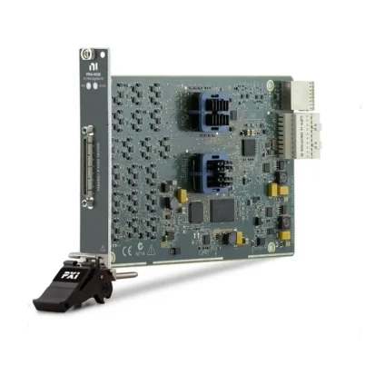
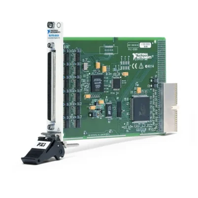
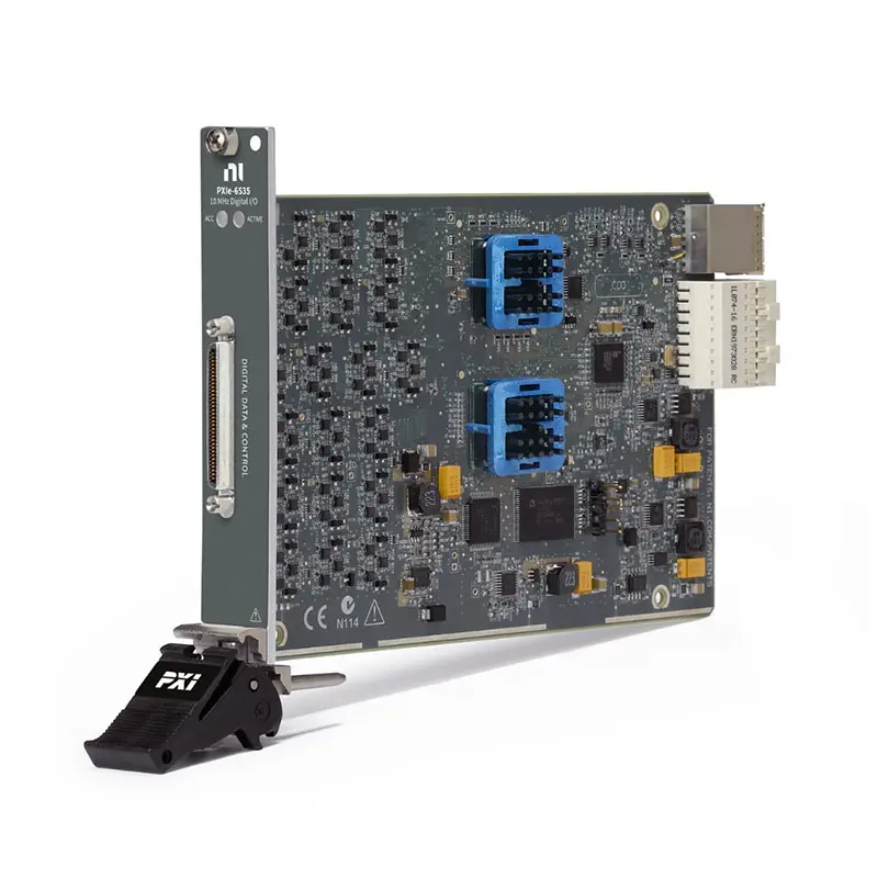
PXIe-6535 32-Channel 10 MHz High-Speed Digital I/O Module
Земля NI PXIe-6535 is a high-speed digital I/O module designed for continuous data streaming, pattern generation, digital acquisition, change detection and custom protocol emulation. It provides 32 bidirectional single-ended digital channels, a maximum sample clock rate of 10 MHz and aggregate streaming bandwidth of up to 40 MB/s.
The module supports selectable 2.5 V, 3.3 V and 5 V TTL-compatible logic levels. Each channel offers independent direction control, allowing digital inputs and outputs to be combined within the same application.
Its PXI Express interface supports continuous DMA transfer between the module and host memory. This makes the PXIe-6535 suitable for pattern I/O, image and display device testing, protocol emulation and other applications requiring long or continuously changing digital data streams.
PXIe-6535 Product Overview
The PXIe-6535 is the 10 MHz model in the NI PXIe-653x high-speed digital I/O family. It provides the same 32-channel architecture and flexible timing functions as the higher-speed PXIe-6536 and PXIe-6537, but is optimized for applications that do not require more than 40 MB/s of aggregate throughput.
When all 32 channels are used, the module transfers a four-byte digital word with every sample clock. At the maximum 10 MHz sample rate, the resulting aggregate data throughput is 40 MB/s.
The PXIe-6535 supports hardware-timed pattern generation, continuous digital acquisition, handshake operation, change detection, pattern matching and software-timed static I/O. Its standard NI part number is 780695-01.
Key Features of the PXIe-6535
32 Bidirectional Digital Channels
The PXIe-6535 provides 32 single-ended digital I/O channels. The channels can be used as one 32-bit interface or divided into smaller 8-bit, 16-bit and custom-width groups.
Per-Channel Direction Control
Each digital line can be independently configured as an input or output. This provides greater flexibility than digital modules that require an entire port to operate in one direction.
10 MHz Maximum Sample Clock
The module supports hardware-timed digital operations at sample clock rates up to 10 MHz. It can use its internal timing engine or an external clock supplied through a clock-capable PFI terminal or PXI backplane resource.
Up to 40 MB/s Aggregate Streaming
The PXIe-6535 can continuously stream 32-bit digital samples at up to 10 million samples per second, producing an aggregate transfer rate of 40 MB/s.
Actual sustained performance depends on the PXI Express chassis, controller, host memory, software buffers and other modules sharing the system bandwidth.
Selectable Logic Levels
The PXIe-6535 supports 2.5 V, 3.3 V and 5 V TTL-compatible digital logic. The 5 V TTL-compatible mode uses 3.3 V output levels with input thresholds suitable for 5 V TTL signals.
Continuous DMA Transfers
DMA transfers move generated and acquired data between the module and host memory. This architecture enables long-duration digital operations without requiring the complete waveform to fit within onboard memory.
Pattern Generation and Acquisition
The module can generate predefined parallel patterns and acquire DUT responses using hardware sample-clock timing. These functions are useful for digital interface simulation and automated functional testing.
Change Detection
Change-detection timing captures digital data when selected input channels transition. It reduces unnecessary data transfer in applications where the signals remain unchanged for long periods.
Handshake Timing
Handshake and burst-handshake modes coordinate data transfers with external ready and acknowledge signals. These timing modes allow communication with devices that cannot sustain a continuous fixed-rate stream.
PXI Clock and Trigger Routing
The PXIe-6535 can route timing signals through its PFI terminals and supported PXI Express backplane resources. It can therefore synchronize digital operations with other PXI модули.
PXIe-6535 Technical Specifications
| Product Model | NI PXIe-6535 |
|---|---|
| Part Number | 780695-01 |
| Product Type | High-Speed Digital I/O Module |
| Bus and Form Factor | PXI Express, single-slot 3U module |
| Digital I/O Channels | 32 bidirectional channels |
| Direction Control | Per channel |
| Signaling Type | Single-ended |
| Maximum Sample Clock | 10 MHz |
| Maximum Per-Channel Data Rate | 10 Mbit/s |
| Maximum Aggregate Streaming Rate | 40 MB/s with 32-bit data |
| Supported Logic Families | 2.5 V, 3.3 V and 5 V TTL compatible |
| Digital Input Range | -1 V to 6 V |
| Output Impedance | 50 Ω nominal |
| Input Impedance | 50 kΩ nominal |
| Maximum Drive Strength | ±16 mA at 2.5 V; ±32 mA at 3.3 V |
| PFI Channels | 6 bidirectional PFI channels |
| Internal Timebase | 200 МГц |
| Onboard FIFO | 2,048 samples |
| Transfer Methods | DMA and programmed I/O |
| Front Connector | 1 × VHDCI |
| Driver | НИ-DAQmx |
| Module Width | 1 PXI Express slot |
Understanding the 40 MB/s Data Rate
The 40 MB/s specification represents the aggregate transfer rate for all 32 digital channels. A 32-bit sample contains four bytes:
10,000,000 samples/s × 4 bytes/sample = 40 MB/s
Each individual channel therefore supports up to 10 Mbit/s when the module operates at its maximum 10 MHz sample rate.
This aggregate-bandwidth specification should not be confused with digital waveform instruments that normally specify data rate separately for each channel.
How the PXIe-6535 Works
During digital generation, an application creates a host-memory buffer containing the required pattern data. NI-DAQmx transfers the data through the PXI Express bus to the module’s onboard FIFO. The PXIe-6535 outputs each digital word according to the selected sample clock.
During acquisition, the module samples the digital input channels and stores data temporarily in the FIFO. DMA continuously transfers the samples to host memory for storage, decoding or analysis.
The FIFO helps absorb short variations in bus timing, while the PXI Express connection supplies the sustained bandwidth required for continuous operation.
Supported Digital Timing Modes
Sample Clock Timing
Sample clock timing generates or acquires one digital word on every selected clock edge. The sample clock can come from the internal timing engine, a PFI terminal or a supported PXI backplane resource.
Pipelined Sample Clock
Pipelined sample-clock timing provides additional timing control between the digital data and clock. It can help satisfy the setup-and-hold requirements of an external device.
Burst Handshake
Burst-handshake timing transfers blocks of data while using external flow-control signals. This is useful when the DUT accepts or provides data in bursts rather than as a continuous stream.
Handshake Timing
Handshake mode coordinates individual transfers with ready and acknowledge signals. It supports devices whose response time may vary between samples.
Change Detection
Change-detection acquisition records digital states when selected channels change. Rising edges, falling edges or both edge directions can be monitored according to the application.
On-Demand Digital I/O
Software-timed operation is available for applications that do not require deterministic hardware timing. The host application can directly read or write digital states using NI-DAQmx.
Continuous Digital Streaming
The PXIe-6535 is designed for continuous data movement rather than deep onboard waveform storage. Generated and acquired data can be transferred during operation, allowing tests to run for longer than the onboard FIFO capacity.
Continuous streaming is useful for:
- Long nonrepeating digital patterns
- Extended digital monitoring
- Continuous protocol traffic
- Image sensor data acquisition
- Display-panel pattern generation
- Production tests with changing pattern data
The PXI controller and software buffers must be able to sustain the required data rate throughout the test.
Pattern Generation and Protocol Emulation
The PXIe-6535 can emulate digital devices and proprietary parallel interfaces by generating user-defined data words and timing signals.
Common pattern-generation tasks include:
- Sending DUT initialization commands
- Generating address and data sequences
- Simulating digital sensor outputs
- Creating functional test patterns
- Generating display-panel data
- Implementing custom parallel protocols
Protocol encoding and response interpretation are normally implemented in the host application, while the module manages hardware-timed digital transfer.
Image Sensor and Display Testing
The PXIe-6535 can acquire parallel image-sensor data or generate digital patterns for display-panel testing when the interface remains within its channel, voltage and timing specifications.
Its 32 channels can carry pixel data, synchronization signals and device-control lines. Continuous PXI Express streaming allows long sequences to be transferred without storing the complete dataset onboard.
Change Detection Applications
Change detection allows the module to acquire data only when selected digital states transition. This can reduce the amount of transferred data when input signals remain stable for extended periods.
Typical change-detection uses include:
- Digital status monitoring
- Asynchronous event capture
- Encoder transition monitoring
- Control-line state recording
- Triggering additional system measurements
Noisy input signals may create multiple unintended transitions. External signal conditioning or filtering may be required when signals do not have clean digital edges.
Typical PXIe-6535 Applications
- High-speed pattern I/O
- Parallel digital bus testing
- Image sensor interface testing
- Display-panel testing
- Custom protocol emulation
- Change-detection acquisition
- FPGA and embedded controller validation
- Digital sensor simulation
- Digital stimulus and response testing
- Hardware-in-the-loop testing
- Electronic component characterization
- Automated production testing
- Research and laboratory systems
PXIe-6535 Software Support
The PXIe-6535 is controlled through the НИ-DAQmx driver. NI-DAQmx provides functions for digital channel configuration, sample timing, pattern generation, acquisition, triggering, buffering and data transfer.
Common development environments include:
- ЛабВью
- LabWindows/CVI
- Microsoft Visual C/C++
- .NET languages, including C# and Visual Basic .NET
- Python through compatible NI-DAQmx APIs
- NI TestStand integration
NI Measurement & Automation Explorer can be used to detect the module, perform a self-test, confirm driver installation and view PXI system information.
PXIe-6535 System Requirements
A complete PXIe-6535 system normally requires:
- A compatible PXI Express chassis
- An embedded PXI controller or external computer interface
- NI-DAQmx driver software
- A compatible 68-pin digital cable
- A terminal block, breakout accessory or custom fixture
- Application development software
Before ordering, verify the PXI Express slot type, controller operating system, NI-DAQmx version, required digital bandwidth and DUT connection method.
Compatible Cables and Accessories
Common connectivity options include:
- SHC68-C68-D4 shielded digital cable
- C68-C68-D4 unshielded digital cable
- SCB-68A shielded connector block
- TBX-68 connector block
- CB-68LP unshielded connector block
- Custom digital interface fixtures
Use shielded cabling in electrically noisy environments. Custom fixtures should provide appropriate grounding and avoid long unterminated signal branches.
Signal-Integrity Considerations
Digital edge rates contain higher-frequency components than the 10 MHz sample-clock specification may suggest. Cable length, grounding, impedance discontinuities and DUT loading can therefore affect measurement reliability.
Recommended practices include:
- Use short, compatible digital cables
- Provide a low-inductance ground connection
- Avoid unnecessary adapters and long signal stubs
- Select the correct logic family before connecting the DUT
- Confirm that inputs remain within the specified voltage range
- Verify setup-and-hold timing at the DUT connector
- Use shielded accessories in noisy environments
PXIe-6535 vs PXIe-6536
| Спецификация | PXIe-6535 | PXIe-6536 |
|---|---|---|
| Digital Channels | 32 | 32 |
| Maximum Sample Clock | 10 MHz | 25 MHz |
| Maximum Aggregate Streaming | 40 MB/s | 100 MB/s |
| Logic Levels | 2.5 V, 3.3 V and 5 V TTL compatible | 2.5 V, 3.3 V and 5 V TTL compatible |
| Direction Control | Per channel | Per channel |
| General Positioning | Lower-speed digital streaming | Medium-speed digital streaming |
Земля PXIe-6536 is the appropriate upgrade when an application requires more than a 10 MHz sample clock or 40 MB/s aggregate throughput.
PXIe-6535 vs PXIe-6537
| Спецификация | PXIe-6535 | PXIe-6537 |
|---|---|---|
| Digital Channels | 32 | 32 |
| Maximum Sample Clock | 10 MHz | 50 MHz |
| Maximum Aggregate Streaming | 40 MB/s | 200 MB/s |
| Logic Levels | 2.5 V, 3.3 V and 5 V TTL compatible | 2.5 V, 3.3 V and 5 V TTL compatible |
| Direction Control | Per channel | Per channel |
| General Positioning | Cost-effective 10 MHz model | Higher-performance 50 MHz model |
Земля PXIe-6537 provides five times the clock rate and aggregate throughput of the PXIe-6535 for more demanding digital interfaces.
PXIe-6535 vs PXIe-6544
| Спецификация | PXIe-6535 | PXIe-6544 |
|---|---|---|
| Instrument Type | Streaming digital I/O | Digital waveform instrument |
| Digital Channels | 32 | 32 |
| Maximum Clock Rate | 10 MHz | 100 MHz |
| Logic Levels | 2.5 V, 3.3 V and 5 V TTL compatible | 1.2 V, 1.5 V, 1.8 V, 2.5 V and 3.3 V |
| Driver | НИ-DAQmx | NI-HSDIO |
| Primary Advantage | Continuous host-memory streaming | Higher-speed waveform generation and analysis |
Земля PXIe-6544 is better suited to higher-speed waveform testing and lower-voltage logic interfaces. The PXIe-6535 is intended for continuous NI-DAQmx streaming and flexible per-channel digital I/O.
Recommended Related Products
- PXIe-6536 – 32-channel, 25 MHz digital I/O module with up to 100 MB/s aggregate streaming.
- PXIe-6537 – 32-channel, 50 MHz digital I/O module with up to 200 MB/s aggregate streaming.
- PCIe-6535B – computer-based PCI Express version for systems that do not use a PXI chassis.
- PXIe-6544 – 32-channel, 100 MHz digital waveform instrument for higher-speed patterns.
- PXIe-6509 – high-channel-count static digital I/O module for control and monitoring.
- PXIe-1085 – high-bandwidth PXI Express chassis for automated test systems.
PXIe-6535 Selection Guidance
Before selecting the PXIe-6535, confirm that:
- The application requires no more than 32 digital channels
- The DUT uses single-ended digital signaling
- The DUT supports 2.5 V, 3.3 V or 5 V TTL logic
- The required sample clock does not exceed 10 MHz
- The aggregate throughput does not exceed 40 MB/s
- Per-channel direction control is required
- Continuous host-memory streaming is preferred
- The PXI Express chassis and controller are compatible
Common Troubleshooting Checks
The PXIe-6535 Is Not Detected
Confirm that the module is fully seated in a compatible PXI Express slot and that a supported NI-DAQmx driver is installed. Use NI MAX to check whether the hardware appears and passes its self-test.
Continuous Streaming Stops
Check for buffer underflow during generation or overflow during acquisition. Increase the host buffer, transfer larger blocks and verify that the controller can sustain the required data rate.
Digital Data Contains Timing Errors
Verify the clock source, active edge, logic family and channel direction. Inspect cable length, grounding and DUT setup-and-hold timing.
The DUT Does Not Recognize the Output
Confirm the selected logic family, channel mapping, bit order, pattern data and handshake settings. Verify that the DUT shares a suitable ground connection with the test system.
Change Detection Produces Extra Events
Check whether rising edges, falling edges or both are enabled. Inspect the input signal for noise or slow transitions that may cause repeated detection.
An External Clock Is Not Detected
Verify that the clock is connected to a clock-capable PFI terminal and remains within the supported voltage and frequency limits. Confirm the selected source and active edge in NI-DAQmx.
Frequently Asked Questions
What is the PXIe-6535 used for?
The PXIe-6535 is used for digital pattern generation, continuous acquisition, protocol emulation, change detection and automated device testing.
How many digital channels does the PXIe-6535 provide?
It provides 32 bidirectional single-ended digital channels.
What is the maximum sample clock rate?
The maximum sample clock rate is 10 MHz.
What does the 40 MB/s specification mean?
It represents the aggregate transfer rate for a 32-bit digital stream operating at 10 MHz.
What is the maximum data rate per channel?
Each individual digital channel can operate at up to 10 Mbit/s.
Which logic levels are supported?
The PXIe-6535 supports 2.5 V, 3.3 V and 5 V TTL-compatible logic.
Can each digital channel have a different direction?
Yes. Each channel can be independently configured as an input or output.
Does the PXIe-6535 support continuous streaming?
Yes. DMA transfers allow generated and acquired data to move continuously between the module and host memory.
Does the PXIe-6535 have deep onboard memory?
No. It uses a 2,048-sample FIFO and is designed primarily for continuous host-memory streaming.
Which driver controls the PXIe-6535?
The module is controlled through the NI-DAQmx driver.
What is the PXIe-6535 part number?
The standard NI part number is 780695-01.
Can the PXIe-6535 operate independently?
No. It requires a compatible PXI Express chassis and an embedded controller or external computer interface.
Why Choose the PXIe-6535?
The PXIe-6535 is a cost-effective choice for applications requiring continuous 32-bit digital streaming at sample rates up to 10 MHz. It combines per-channel direction control, selectable logic levels, multiple timing modes and 40 MB/s aggregate throughput.
Its NI-DAQmx support and PXI Express architecture simplify integration into laboratory, validation and automated production test systems.
Request a Quote for the PXIe-6535
Contact us for current availability, lead time and project pricing for the NI PXIe-6535 High-Speed Digital I/O Module, part number 780695-01.
We can also help identify compatible PXI Express chassis, embedded controllers, SHC68-C68-D4 cables, terminal blocks and related digital I/O modules for your test system.















