






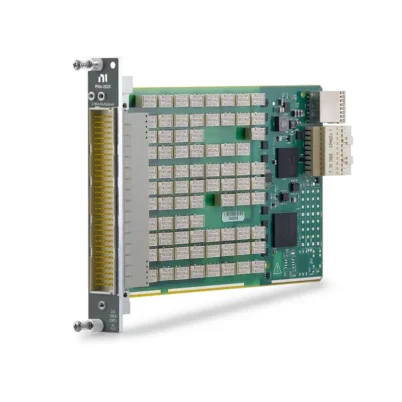
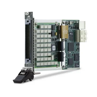
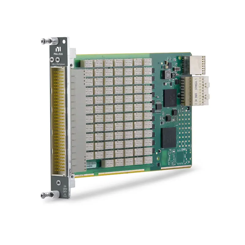
PXIe-2526 158-Channel Multiplexer Switch Module
Земля PXIe-2526 is a high-density PXI Express multiplexer switch module designed for automated test, data acquisition and multichannel signal-routing systems. It provides up to 158 one-wire channels или 79 two-wire channels in a single PXI Express slot.
With maximum switching levels of 150 VDC, 2 A и 60 W, the PXIe-2526 can route signals from sensors, electronic devices and test points to measurement instruments such as digital multimeters and digitizers. Electromechanical relays provide low path resistance and reliable isolation between channels.
Key Features of the PXIe-2526
- 158-channel high-density multiplexer switch module
- 158×1 one-wire multiplexer topology
- 79×1 two-wire multiplexer topology
- 150 V maximum switching voltage
- 2 A maximum switching and carry current per channel
- 60 W or 62.5 VA maximum switching power
- 1,000-cycle-per-second maximum scan rate
- 10 MHz typical bandwidth
- Electromechanical non-latching relays
- Onboard relay-count monitoring
- 160-position DIN front-panel connector
- PXI Express platform compatibility
PXIe-2526 Technical Specifications
| Product Model | PXIe-2526 |
|---|---|
| Part Number | 780587-26 |
| Product Type | PXI Express Multiplexer Switch Module |
| Maximum Channel Count | 158 one-wire channels or 79 two-wire channels |
| Multiplexer Topologies | 158×1 one-wire and 79×1 two-wire |
| Maximum Switching Voltage | 150 VDC, channel-to-channel or channel-to-ground |
| Maximum Switching Current | 2 A per channel |
| Maximum Carry Current | 2 A per channel |
| Maximum Switching Power | 60 W or 62.5 VA |
| Minimum Switch Load | 20 mV, 1 mA |
| Initial DC Path Resistance | Less than 0.5 Ω |
| Thermal EMF | Less than 10 µV |
| Пропускная способность | 10 MHz typical |
| Maximum Scan Rate | 1,000 cycles/s |
| Typical Relay Operating Time | 1 ms |
| Тип реле | Electromechanical, non-latching |
| Mechanical Relay Life | Up to 100 million cycles |
| Front Connector | 160-position DIN 41612 male |
| Operating Temperature | 0°C to 55°C |
| Шинный интерфейс | PXI Express |
PXIe-2526 Part Number and Accessories
| Item | Part Number | Описание |
|---|---|---|
| PXIe-2526 | 780587-26 | 158-channel, 2 A PXI Express multiplexer switch module |
| 160-Pin DIN to Four D-Sub Cable | 782417-03 | Breaks the module connection into four D-Sub interfaces |
| TBX-50 Terminal Block | 779305-01 | 50-pin screw-terminal connectivity accessory |
| TBX-50B Terminal Block | 782866-01 | Updated 50-pin terminal block for field wiring |
| 160-Pin DIN to 160-Pin DIN Cable | 781090-02 | Custom connectivity cable |
| 160-Pin DIN to Bare-Wire Cable | 781090-03 | Bare-wire cable for custom fixtures and test systems |
Accessory requirements depend on the selected topology, terminal arrangement and test-fixture design. Verify cable pinouts and terminal-block compatibility before ordering.
High-Density Multiplexer Architecture
The PXIe-2526 consolidates as many as 158 signal channels into one PXI Express module. This density helps reduce chassis space, cabling complexity and the number of switch modules required in large automated test systems.
The multiplexer routes one selected input channel to a common output. The common connection can then be connected to a digital multimeter, digitizer, data acquisition device or another measurement instrument.
158×1 One-Wire Multiplexer Topology
In the 158×1 one-wire configuration, the PXIe-2526 routes one of 158 individual signal lines to a common terminal. This configuration provides the module’s highest channel density and is suitable when the signals share a common return or reference connection.
Typical uses include single-ended voltage monitoring, continuity testing, signal presence detection and automated functional testing of densely populated electronic assemblies.
79×1 Two-Wire Multiplexer Topology
The 79×1 two-wire configuration switches the signal and return lines together. It provides 79 two-wire input channels connected to a two-wire common output, helping isolate both conductors of the selected signal path.
This topology is useful for floating voltage signals, differential measurements and applications where switching only one conductor would not provide sufficient isolation.
150 V and 2 A Switching Capability
The PXIe-2526 supports switching voltages up to 150 VDC and switching or carrying currents up to 2 A per channel. Its maximum switching power is 60 W for DC loads or 62.5 VA for AC loads.
These ratings make the module suitable for routing many low-frequency measurement and control signals. The voltage, current and power limits must all be observed simultaneously when determining whether a load is compatible.
CAT I Signal Switching
The PXIe-2526 is intended for CAT I measurement and signal-routing applications. It must not be connected directly to building mains or circuits classified as CAT II, CAT III or CAT IV.
Appropriate insulation, external protection and signal conditioning should be used when the source may exceed the module’s working-voltage or transient limits.
Low Path Resistance and Thermal EMF
The module provides initial DC path resistance below 0.5 Ω and thermal EMF below 10 µV. These characteristics help reduce switching-related errors in voltage monitoring and general-purpose automated measurements.
Relay resistance can increase over time as the contacts age. Applications sensitive to small resistance changes should include periodic path verification and relay-condition monitoring.
10 MHz Typical Bandwidth
With a typical bandwidth of 10 MHz, the PXIe-2526 can route DC and moderate-frequency signals used in functional testing, sensor acquisition and electronic device validation.
Actual system bandwidth also depends on cable length, fixture design, source impedance, load impedance and the measurement instrument connected to the common terminal.
Electromechanical Relays and Relay Monitoring
The PXIe-2526 uses non-latching electromechanical relays with gold-covered palladium-ruthenium contacts. The relays provide physical signal isolation and a mechanical life of up to 100 million cycles under suitable operating conditions.
Onboard relay counting helps maintenance teams monitor channel usage and identify heavily used relays before they affect production testing. The relay-count information can support preventive-maintenance schedules and system-health checks.
High-Speed Automated Scanning
The module supports scanning rates of up to 1,000 cycles per second. Test software can automatically connect a sequence of channels to a shared measurement instrument, allowing one instrument to acquire data from many test points.
The achievable system measurement rate also depends on relay settling time, instrument aperture, trigger configuration, software overhead and the required measurement accuracy.
Typical PXIe-2526 Applications
- High-density automated test systems
- Multichannel voltage monitoring
- Electronic device functional testing
- Production test and manufacturing validation
- Sensor signal routing
- Battery and power-system testing
- Data acquisition channel expansion
- Continuity and connection verification
- Environmental and reliability testing
- Research laboratory switching systems
Multichannel Measurement Systems
The PXIe-2526 can expand the channel capacity of a PXI measurement instrument by sequentially routing many test points to a single input. For example, it can be paired with a PXIe-4080 digital multimeter to create a compact multichannel voltage-measurement system.
This architecture can reduce instrument count and system cost when the application does not require every channel to be measured simultaneously.
Resistance Measurement Considerations
The PXIe-2526 is not recommended for precision two-wire resistance measurements because relay and cable resistance become part of the measured value. These effects can be significant when measuring low-resistance devices.
For precision resistance testing, consider a four-wire switching configuration and a compatible digital multimeter. Four-wire sensing separates the current-carrying path from the voltage-sensing path and reduces lead-resistance errors.
NI-SWITCH Software Support
The PXIe-2526 is controlled through the NI-SWITCH instrument driver. NI-SWITCH provides functions for configuring topologies, connecting and disconnecting channels, creating scan lists, managing triggers and reading relay-count information.
The driver can be used with development environments such as LabVIEW, LabWindows/CVI and supported text-based programming languages.
NI Switch Executive Integration
NI Switch Executive can simplify the management of complex signal routes by allowing engineers to define routes using meaningful signal names. This is useful when the PXIe-2526 is combined with additional switch modules in a larger test system.
Named routes can make test sequences easier to maintain and reduce the need to manage individual relay connections directly within application code.
PXI Express Chassis Integration
The PXIe-2526 installs in a compatible PXI Express chassis and occupies one peripheral slot. A PXI controller or external computer interface manages the module and coordinates it with other measurement instruments.
Before integration, confirm chassis slot compatibility, available cooling capacity, cable clearance and the software versions supported by the selected operating system.
PXIe-2526 Troubleshooting
The module is not detected by the system
Confirm that the module is fully seated in a compatible PXI Express slot. Verify chassis operation, controller communication and NI-SWITCH installation, then inspect the module in NI Measurement & Automation Explorer.
A selected channel does not connect
Check that the correct topology is configured and verify the channel names used by the application. Inspect the cable, terminal block and external wiring, and review the relay count if the channel has received extensive use.
Measurements are unstable or inaccurate
Allow sufficient relay and signal settling time before taking a measurement. Check grounding, shielding, cable routing, source impedance and instrument input settings. Also confirm that voltage, current and power remain within the module ratings.
The scan rate is lower than expected
Review the measurement instrument’s aperture and settling settings, software timing and scan-list configuration. The overall test rate is determined by the complete measurement system, not only by the switch module’s relay speed.
Two-wire resistance readings are too high
The reading can include relay, cable and fixture resistance. The PXIe-2526 is not recommended for precision two-wire resistance measurements; use an appropriate four-wire switching solution when low-resistance accuracy is required.
PXIe-2526 Comparison
| Модель | Primary Configuration | Best Suited For |
|---|---|---|
| PXIe-2526 | 158×1 one-wire or 79×1 two-wire | Maximum one-wire and two-wire channel density |
| PXIe-2525 | Configurable multibank two-wire multiplexer | Applications requiring independently controlled switch banks |
| PXIe-2527 | General-purpose multiplexer configurations | Systems requiring fewer channels or different routing options |
| PXIe-2575 | High-density multiplexer with additional topology options | Large two-wire or four-wire measurement systems |
Recommended Related Products
- PXIe-2525 Multibank Multiplexer Switch Module
- PXIe-2524 Multiplexer Switch Module
- PXIe-2527 Multiplexer Switch Module
- PXIe-2575 High-Density Multiplexer Switch Module
- PXIe-4080 Digital Multimeter
- View More NI PXI and PXI Express Modules
Selecting the Right Multiplexer Module
Choose the PXIe-2526 when the system requires up to 158 one-wire channels or 79 two-wire channels in a single PXI Express slot. It is especially useful for applications where channel density, 2 A capacity and automated scanning are the primary requirements.
Before ordering, consider the required topology, signal voltage, current, switching power, bandwidth, measurement accuracy and connector accessories. Applications involving precision resistance measurements or additional switched conductors may require a different multiplexer configuration.
PXIe-2526 vs PXIe-2525
The PXIe-2526 provides a single high-density 158×1 one-wire or 79×1 two-wire multiplexer. The PXIe-2525 provides configurable multibank two-wire topologies, making it more suitable when several independently controlled multiplexer banks are required.
Select the PXIe-2526 for maximum channel concentration around one common connection. Select the PXIe-2525 when the test architecture requires multiple separate common terminals or independently operated switching groups.
Why Choose the PXIe-2526?
- Routes as many as 158 one-wire signals in one PXI Express slot
- Supports both one-wire and two-wire multiplexer operation
- Handles switching levels up to 150 V and 2 A
- Provides fast automated scanning for production test
- Includes onboard relay-count monitoring
- Integrates with NI-SWITCH and NI Switch Executive
- Works with PXI instruments to create compact automated measurement systems
Frequently Asked Questions
What is the PXIe-2526?
The PXIe-2526 is a high-density PXI Express multiplexer switch module. It routes one of many input channels to a common connection for automated measurement and signal-monitoring applications.
How many channels does the PXIe-2526 provide?
It provides 158 channels in the 158×1 one-wire topology or 79 paired channels in the 79×1 two-wire topology.
What is the maximum switching voltage?
The maximum switching voltage is 150 VDC, channel-to-channel or channel-to-ground, for CAT I signal applications.
What is the maximum switching current?
The PXIe-2526 supports up to 2 A of switching or carry current per channel, subject to its voltage, power and simultaneous-relay limitations.
What is the maximum scan rate?
The module supports scan rates of up to 1,000 cycles per second. Actual measurement throughput depends on relay settling, instrument configuration and application timing.
Can the PXIe-2526 perform four-wire resistance measurements?
No. Its available topologies are 158×1 one-wire and 79×1 two-wire. A switch module with a dedicated four-wire topology is recommended for precision low-resistance measurements.
Which software controls the PXIe-2526?
The module is controlled using the NI-SWITCH driver. NI Switch Executive can also be used to create and manage named signal routes in complex switching systems.
What is the PXIe-2526 part number?
The standard NI part number for the PXIe-2526 is 780587-26.
Request a Quote for the PXIe-2526
Contact us for current availability, lead time and project pricing for the PXIe-2526 158-Channel Multiplexer Switch Module. We can also help identify compatible PXI Express chassis, cables, terminal blocks, digital multimeters and related switch modules for your test system.















