







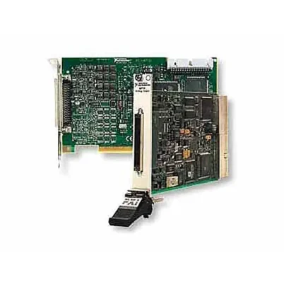
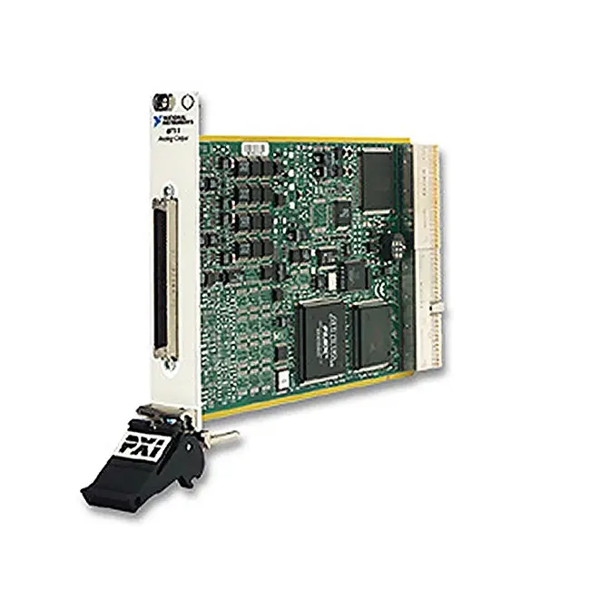
PXI-6711 4-Channel High-Speed Analog Output Module
Земля PXI-6711 is a high-speed PXI analog output module designed for waveform generation, deterministic control, sensor simulation and stimulus-response testing. It provides four independent voltage output channels with 12-bit resolution, a ±10 V output range and simultaneous update rates of up to 1 MS/s per channel.
The PXI-6711 also includes eight TTL/CMOS-compatible digital I/O lines, two 24-bit counter/timers, digital triggering and external clocking. These capabilities allow it to replace multiple low-speed function generators, waveform generators and standalone control instruments in automated PXI systems.
Key Features of the PXI-6711
- Four independent analog voltage outputs
- Simultaneous multichannel updating
- 12-bit analog output resolution
- 1 MS/s maximum update rate per channel
- ±10 V standard analog output range
- External voltage reference support
- Approximately 20 V/µs typical slew rate
- Approximately 3 µs full-scale settling time
- ±5 mA maximum output current drive
- 8,192-sample onboard waveform FIFO
- Periodic and nonperiodic waveform generation
- Eight 5 V TTL/CMOS digital I/O lines
- Two 24-bit, 20 MHz counter/timers
- Digital triggering and external clocking
- PXI trigger-bus synchronization
- 68-pin SCSI-type front connector
- PXI hybrid-slot compatible
- NI-DAQmx software support
PXI-6711 Technical Specifications
| Product Model | PXI-6711 |
|---|---|
| Part Number | 777794-01 |
| Product Type | High-speed PXI analog output module |
| Шинный интерфейс | PXI hybrid |
| Analog Output Channels | 4 voltage outputs |
| Analog Output Resolution | 12 bits |
| Maximum Update Rate | 1 MS/s per channel with one to four channels active |
| Simultaneous Updating | Да |
| Standard Output Range | ±10 V |
| External Reference | Supported |
| DAC Architecture | Double-buffered multiplying DAC |
| Output Coupling | DC |
| Maximum Current Drive | ±5 mA |
| Typical Slew Rate | 20 V/µs |
| Typical Full-Scale Settling Time | Approximately 3 µs to within ±1 LSB |
| Output FIFO | 8,192 samples |
| Waveform Generation | Periodic and nonperiodic buffered generation |
| Digital I/O Lines | 8 bidirectional 5 V TTL/CMOS lines |
| Counter/Timers | 2 |
| Counter Resolution | 24 bits |
| Counter Timebase | 20 MHz |
| Запуск | Digital start and update triggering |
| Clocking | Internal or external update clock |
| PXI Synchronization | PXI trigger bus and reference-clock resources |
| Front Connection | 68-pin SCSI type |
| Module Format | 3U PXI |
| Поддержка программного обеспечения | НИ-DAQmx |
| Lifecycle Status | Discontinued with limited NI support |
| Recommended NI Replacement | PXIe-6738, part number 783800-01 |
PXI-6711 Part Number and Accessories
| Item | Part Number | Описание |
|---|---|---|
| PXI-6711 | 777794-01 | Four-channel, 12-bit, 1 MS/s PXI analog output module |
| SH68-68-EP Cable | 199006-01 | 1 m shielded 68-pin cable for connection to compatible DAQ accessories |
| SCB-68A | 782536-01 | Shielded 68-pin screw-terminal connector block |
| BNC-2110 | 777643-01 | BNC terminal accessory for analog output, digital and timing signals |
| BNC-2120 | 777960-01 | Desktop BNC accessory with signal access and built-in test functions |
| TBX-68 | 777141-01 | DIN-rail-mountable 68-pin screw-terminal block |
| CB-68LP | 777145-01 | Low-cost 68-pin connector block for custom fixtures |
The PXI-6711 uses a 68-pin SCSI-type front connector rather than a modern VHDCI interface. Verify the connector on both ends of the cable before ordering an accessory for an existing system.
Four Independent Analog Outputs
The PXI-6711 provides four independent voltage output channels. Each channel can generate its own waveform or static control voltage, allowing several unrelated stimulus and control signals to be produced by one module.
Every output has a dedicated DAC and can be updated simultaneously with the other channels. This preserves the programmed timing relationship between multichannel waveforms.
Simultaneous Multichannel Updates
All four outputs can update at up to 1 MS/s per channel. Simultaneous updating is important for three-phase signal simulation, multiaxis control and applications in which phase relationships between outputs must remain consistent.
The update clock loads new values into the channel DACs at the same point in the generation cycle. This avoids the channel-to-channel skew associated with multiplexed analog output architectures.
12-Bit Output Resolution
Each output uses a 12-bit DAC, providing 4,096 theoretical voltage levels across the configured range. With the standard ±10 V range, one ideal least-significant bit represents approximately 4.88 mV.
Actual output accuracy also depends on gain error, offset error, temperature, reference accuracy, load and calibration status. Applications requiring finer voltage resolution should consider a 16-bit analog output module.
±10 V Output Range
The standard output range is -10 V to +10 V. This range is compatible with many laboratory instruments, control systems, amplifier inputs and simulated sensor interfaces.
The output channels are ground referenced and are not isolated from the PXI system. External isolation should be added when field equipment has significant ground-potential differences or requires galvanic separation.
External Voltage Reference
The multiplying DAC architecture allows the output channels to use either the onboard reference or a suitable external voltage reference. An external reference can scale the effective output range for specialized applications.
All reference voltage and output terminal limits must be observed. The external reference source should provide sufficient stability and low noise for the desired output performance.
1 MS/s Waveform Generation
Each channel can generate new voltage values at up to one million updates per second. This allows the PXI-6711 to produce sine, square, triangular, sawtooth, arbitrary and application-specific waveforms.
The useful waveform frequency depends on the number of samples used per cycle and the settling requirements of the connected load. Higher waveform fidelity generally requires more samples per period.
High Slew Rate and Fast Settling
The analog output circuitry provides a typical slew rate of approximately 20 V/µs. It typically settles to within approximately ±1 LSB of a full-scale step in about 3 µs.
Large voltage transitions, capacitive loads and long cables can increase settling time. Verify output behavior under the actual loading and wiring conditions used by the test fixture.
±5 mA Output Current
Each output can drive a load current of up to approximately ±5 mA within the specified operating conditions. This is suitable for high-impedance instrumentation and controller inputs.
The analog outputs should not be used to power loads directly. Add an external voltage amplifier, current driver or power stage when the connected equipment requires more current.
Onboard Waveform FIFO
The PXI-6711 includes an 8,192-sample onboard FIFO for analog waveform generation. Waveform data can be transferred from the host into the buffer and then clocked to the DACs at a deterministic rate.
Short periodic waveforms can be regenerated from onboard memory without repeatedly transferring every point across the PXI bus. Longer or changing waveforms can be streamed from host memory using NI-DAQmx.
Periodic Waveform Generation
Periodic regeneration repeatedly outputs the waveform stored in the buffer. This is useful for continuous sine waves, repeating control profiles and cyclic sensor simulations.
The waveform length, update rate and number of samples per period determine the generated frequency. Test software can replace or modify the waveform as required by the application.
Nonperiodic Waveform Generation
Nonperiodic generation outputs a finite or continuously changing sequence of voltage values. It can reproduce transient events, startup profiles, ramps and prerecorded sensor signals.
Continuous nonperiodic generation requires the PXI controller and application to supply data quickly enough to prevent an output-buffer underflow.
Deterministic Control Applications
The hardware-timed outputs can generate repeatable control signals without relying on nondeterministic software timing for every update. This is useful for high-speed closed-loop experiments, hardware-in-the-loop testing and actuator command simulation.
Complete loop determinism depends on the controller, operating system, measurement hardware and application architecture. The PXI-6711 itself does not contain a user-programmable FPGA.
Sensor and Signal Simulation
The PXI-6711 can simulate voltage-output sensors and electronic control signals. Engineers can reproduce normal values, ramps, oscillations, dropouts and fault profiles while validating a controller or data acquisition system.
External protection may be required when connecting to powered controller inputs. Verify that the simulated signal and the connected system do not drive conflicting voltages onto the same line.
Stimulus-Response Testing
The module can generate a controlled voltage stimulus while other PXI instruments acquire the device response. Shared PXI triggers and clocks establish a repeatable relationship between waveform generation and measurement.
Typical tests include frequency response, transient response, component characterization, amplifier testing and control-system validation.
Power-Supply Control
Analog outputs can control the programming inputs of compatible power supplies, electronic loads and amplifiers. Each channel can apply a static setpoint or a time-varying profile.
Before connection, verify the programming-input voltage range, polarity, input impedance and grounding. The PXI-6711 should not be connected directly to the power output terminals of a supply.
Eight Digital I/O Lines
The PXI-6711 includes eight bidirectional 5 V TTL/CMOS-compatible digital I/O lines. These lines can control external logic, monitor status signals and support application-specific timing.
The digital lines are logic-level interfaces and cannot directly operate 24 V industrial equipment. External level conversion, buffering or isolation is required for industrial field signals.
Two 24-Bit Counter/Timers
Two 24-bit counter/timers with a 20 MHz timebase support event counting, frequency measurement, period measurement, pulse-width measurement and pulse generation.
Counter outputs can generate clocks and control pulses for external equipment. Counter and waveform operations can share timing and trigger resources within the PXI system.
Digital Triggering
Digital triggers can start waveform generation at a defined external or backplane event. Hardware triggering provides more repeatable timing than starting each output operation through software alone.
The selected trigger source, active edge and output task must be configured in NI-DAQmx. Ensure that no other PXI module reserves the same trigger line for a conflicting route.
External Clocking
An external update clock can control when the output channels accept new samples. This allows waveform generation to follow an external instrument, encoder or test-system clock.
The external clock must meet the module’s logic-level, pulse-width and frequency requirements. Signal integrity becomes increasingly important as clock frequency increases.
PXI Backplane Synchronization
PXI timing resources allow multiple PXI-6711 modules or other compatible instruments to share triggers and reference clocks. This enables expanded channel counts and synchronized stimulus-response systems.
Backplane routing eliminates many external timing cables, but the acquisition and generation tasks must still be configured to use the intended master clock and trigger sources.
Typical PXI-6711 Applications
- Arbitrary waveform generation
- Function-generator replacement
- Stimulus-response testing
- Sensor and signal simulation
- Hardware-in-the-loop testing
- Power-supply programming
- Actuator command generation
- High-speed deterministic control
- PID control experiments
- Автоматизированное испытательное оборудование
- Production functional testing
- Laboratory automation
- Multichannel phase-coherent generation
Automated Test Equipment
In automated test systems, the PXI-6711 can provide voltage stimulus, simulated sensor signals and programmable control levels. Digital and counter signals can coordinate fixture operations and device-under-test events.
Multiple outputs reduce the need for separate benchtop generators and simplify test-sequence automation through a common NI-DAQmx interface.
Hardware-in-the-Loop Testing
The module can reproduce voltage signals expected from sensors or subsystems during HIL validation. Test software can change output waveforms according to simulated operating conditions and inserted faults.
For deterministic closed-loop applications, evaluate the complete system latency, including input acquisition, controller execution and analog output response.
Laboratory Waveform Generation
Researchers can define each output point to create standard or custom waveforms. Four channels can produce related signals with controlled amplitude, frequency and phase.
The module is most appropriate for low- and moderate-frequency signal generation within its update-rate, settling and output-drive limits.
NI-DAQmx Software Support
The PXI-6711 is controlled through the NI-DAQmx driver. NI-DAQmx supports static writes, finite generation, continuous generation, regeneration, triggering, external clocking, digital I/O and counter operations.
Applications can be developed using LabVIEW, LabWindows/CVI, C/C++ and compatible .NET environments. NI Measurement & Automation Explorer can identify the module and provide basic diagnostic functions.
PXI-6711 Lifecycle and Replacement
The PXI-6711 is discontinued and listed by NI with limited support. It may remain suitable for maintaining existing systems whose wiring, software and calibration procedures depend on this module.
NI identifies the PXIe-6738, part number 783800-01, as the recommended replacement. The PXIe-6738 offers more output channels, 16-bit resolution and a modern PXI Express interface, but it is not a direct drop-in replacement.
PXI-6711 Troubleshooting
The PXI-6711 is not detected in NI MAX
Confirm that the module is fully installed in a compatible PXI or PXI hybrid slot. Check chassis power, controller communication and NI-DAQmx installation, then restart the system.
An analog output remains at 0 V
Verify the physical channel, output task and terminal wiring. Check whether the task has been started and whether an external trigger is configured but has not arrived.
The output waveform has the wrong amplitude
Confirm the programmed range and whether the channel uses the internal or external voltage reference. Measure the load impedance and verify that the output-current limit is not being exceeded.
The waveform is distorted at higher frequencies
Increase the number of samples per cycle where possible and check the output settling requirements. Reduce cable capacitance and use a high-impedance load.
The output cannot drive the connected load
The maximum output current is approximately ±5 mA. Add an external buffer or power amplifier when the load requires more current or has a low input impedance.
Continuous generation stops with a buffer-underflow error
Increase the host buffer, write larger data blocks and avoid slow operations in the waveform-generation loop. Use onboard regeneration when the waveform is periodic.
Multiple outputs are not synchronized
Place the channels in the same hardware-timed analog output task and use one shared sample clock. Confirm that all required channels are configured before starting generation.
Multiple PXI modules do not start together
Configure a shared PXI trigger and reference clock. Start the slave tasks before the master task generates the start trigger.
A digital line cannot control a 24 V relay
The digital lines use 5 V TTL/CMOS levels and cannot directly operate industrial loads. Add an appropriate relay driver, level translator or isolated digital interface.
PXI-6711 Comparison with Similar Analog Output Modules
| Модель | Analog Outputs | Разрешение | Maximum Update Rate | Best Suited For |
|---|---|---|---|---|
| PXI-6711 | 4 | 12 bits | 1 Мвыб/с/кн | Four-channel high-speed waveform generation |
| PXI-6713 | 8 | 12 bits | Up to 1 MS/s/ch | Additional high-speed analog output channels |
| PXI-6722 | 8 | 13 bits | Up to 800 kS/s/ch | Eight-channel generation with higher nominal resolution |
| PXI-6723 | 32 | 13 bits | Up to 800 kS/s/ch | High-channel-count analog stimulus generation |
| PXI-6733 | 8 | 16 bits | Up to 1 MS/s/ch | High-resolution, high-speed waveform generation |
| PXIe-6738 | 32 | 16 bits | Up to 1 MS/s/ch | Modern high-density PXI Express analog output systems |
PXI-6711 vs PXI-6713
Земля PXI-6713 uses the same 12-bit analog output architecture but provides eight channels instead of four. The first four channels can update at up to 1 MS/s per channel, while maximum rate decreases when additional channels are active.
Choose the PXI-6711 when four output channels are sufficient. Choose the PXI-6713 when higher channel density is more important.
PXI-6711 vs PXI-6722
Земля PXI-6722 provides eight 13-bit outputs with update rates up to 800 kS/s per channel. The PXI-6711 provides four 12-bit outputs with a faster 1 MS/s rate.
Select the PXI-6711 for higher speed and four-channel systems. Select the PXI-6722 when eight outputs and its additional nominal resolution better match the application.
PXI-6711 vs PXI-6733
Земля PXI-6733 provides eight analog outputs with 16-bit resolution and rates up to 1 MS/s. It offers finer voltage resolution and twice the channel count of the PXI-6711.
The PXI-6711 remains appropriate for maintaining established 12-bit systems. Choose the PXI-6733 when higher resolution and additional output channels are required.
PXI-6711 vs PXIe-6738
Земля PXIe-6738 is the NI-recommended replacement for the discontinued PXI-6711. It provides 32 analog outputs, 16-bit resolution and a PXI Express interface.
The PXIe-6738 offers substantially greater channel density and resolution, but migration requires reviewing the chassis interface, connector pinout, cable accessories, output timing and application code.
Recommended Related Products
- PXI-6713 8-Channel 12-Bit Analog Output Module
- PXI-6722 8-Channel 13-Bit Analog Output Module
- PXI-6723 32-Channel Analog Output Module
- PXI-6733 8-Channel 16-Bit Analog Output Module
- PXIe-6738 32-Channel 16-Bit Analog Output Module
- PXI-6704 Static Voltage and Current Output Module
- View More NI PXI and PXI Express Modules
Selecting the Right PXI Analog Output Module
Choose the PXI-6711 when an existing PXI system requires four simultaneous ±10 V outputs, 12-bit resolution, 1 MS/s update rates and integrated digital and counter functions.
Select the PXI-6713 for eight similar channels, the PXI-6733 for higher resolution or the PXIe-6738 for a modern PXI Express system requiring substantially greater channel density.
Why Choose the PXI-6711?
- Provides four independent high-speed voltage outputs
- Updates all four channels simultaneously
- Supports rates up to 1 MS/s per channel
- Generates standard and arbitrary waveforms
- Provides a standard ±10 V output range
- Supports an external voltage reference
- Includes onboard waveform memory
- Provides eight digital I/O lines
- Includes two 24-bit counter/timers
- Supports PXI triggering and synchronization
- Integrates with NI-DAQmx applications
Frequently Asked Questions
What is the PXI-6711?
The PXI-6711 is a four-channel, 12-bit PXI analog voltage output module capable of simultaneous waveform generation at up to 1 MS/s per channel.
What is the PXI-6711 part number?
The standard NI part number for the PXI-6711 is 777794-01.
How many analog outputs does the PXI-6711 provide?
It provides four independent voltage output channels.
What is the maximum update rate?
All four outputs can update simultaneously at up to 1 MS/s per channel.
What is the output resolution?
The analog outputs provide 12-bit resolution, corresponding to 4,096 theoretical voltage levels.
What is the output voltage range?
The standard analog output range is -10 V to +10 V. Other effective ranges can be implemented with a suitable external reference.
What is the maximum output current?
Each analog output can drive approximately ±5 mA under the specified operating conditions.
Can the PXI-6711 generate arbitrary waveforms?
Yes. Users can define individual voltage samples to create periodic or nonperiodic arbitrary waveforms.
Does the PXI-6711 update its channels simultaneously?
Yes. All four analog outputs can latch new values simultaneously to preserve multichannel timing relationships.
Does the PXI-6711 provide analog inputs?
No. It is primarily an analog output module. A separate PXI DAQ or digitizer module is required for analog acquisition.
How many digital I/O lines are included?
The module provides eight bidirectional 5 V TTL/CMOS-compatible digital I/O lines.
How many counters are included?
The PXI-6711 provides two 24-bit counter/timers with a 20 MHz timebase.
Which connector does the PXI-6711 use?
It uses a 68-pin SCSI-type front connector. Cable connector style and accessory compatibility should be verified before ordering.
Which software controls the PXI-6711?
The PXI-6711 is controlled through NI-DAQmx and can be used with LabVIEW, LabWindows/CVI, C/C++ and compatible .NET environments.
Is the PXI-6711 discontinued?
Yes. NI lists the PXI-6711 as discontinued with limited support. It may remain available from existing inventory or the tested secondary market.
What is the recommended replacement?
NI recommends the PXIe-6738, part number 783800-01. It is a newer PXI Express module and is not a direct wiring replacement.
Request a Quote for the PXI-6711
Contact us for current availability, condition, lead time and project pricing for the PXI-6711 4-Channel 12-Bit 1 MS/s Analog Output Module. We can also help identify compatible 68-pin cables, connector blocks, PXI chassis and modern high-resolution analog output alternatives.















