




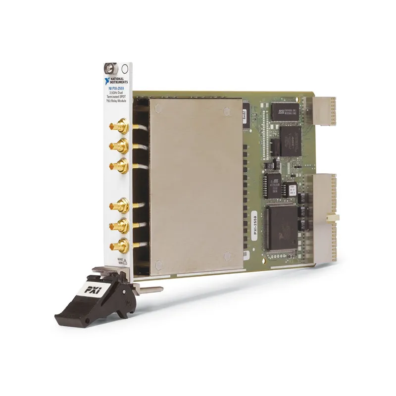
PXI-2559 2.5 GHz Dual Terminated SPDT 75 Ω PXI RF Relay Module
Земля PXI-2559 is a general-purpose PXI RF relay module designed for automated video testing, cable television systems and 75 Ω RF signal routing. It provides two independently controlled, terminated single-pole double-throw relay banks in a single-slot PXI module.
Each bank includes a common connection, a normally open connection and a normally closed connection. Internal 75 Ω termination resistors help minimize reflections on unselected signal paths and protect connected sources, instruments and devices under test from the effects of open-channel impedance.
With a DC to 2.5 GHz frequency range, direct mini-75 Ω SMB connectivity, strong isolation and onboard relay-count tracking, the PXI-2559 is suitable for set-top box testing, video switch networks and automated broadband RF validation.
Key Features of the PXI-2559
- Two independently controlled terminated SPDT relay banks
- Two common, two normally open and two normally closed connections
- Internal 75 Ω termination resistors
- DC to 2.5 GHz frequency range
- 75 Ω nominal characteristic impedance
- Electromechanical latching relays
- Less than 0.9 dB insertion loss through 1 GHz
- Less than 1.7 dB insertion loss through 2.5 GHz
- Greater than 60 dB typical isolation through 1 GHz
- Greater than 55 dB typical isolation through 2.5 GHz
- 30 V maximum switching voltage
- 0.5 A maximum switching and carry current per channel
- 10 W maximum channel-to-common RF power
- 1.5 W termination rating at 25°C
- Less than 20 ps typical channel-to-channel skew
- 45 channels/s maximum scan rate
- Onboard relay-count tracking
- Six gold-plated mini-75 Ω SMB connectors
- PXI hardware trigger support
- NI-SWITCH and NI Switch Executive compatibility
PXI-2559 Technical Specifications
| Product Model | PXI-2559 |
|---|---|
| Part Number | 778572-59 |
| Product Type | PXI RF relay switch module |
| Topology | Dual terminated SPDT |
| Number of Independent Banks | 2 |
| Relay Configuration | SPDT, single-pole double-throw |
| Connections per Bank | COM, normally open and normally closed |
| Termination | Internal 75 Ω termination |
| Диапазон частот | DC to 2.5 GHz |
| Characteristic Impedance | 75 Ω nominal |
| Maximum Switching Voltage | 30 V |
| Maximum Switching Current | 0,5 А на канал |
| Maximum Carry Current | 0,5 А на канал |
| Maximum Channel-to-Common RF Power | 10 W |
| Maximum Termination Power at 25°C | 1.5 W |
| Initial DC Path Resistance | Less than 0.35 Ω |
| End-of-Life DC Path Resistance | 1.0 Ω or greater |
| Maximum Insertion Loss through 1 GHz | Less than 0.9 dB; less than 0.6 dB typical |
| Maximum Insertion Loss through 2.5 GHz | Less than 1.7 dB; less than 1.3 dB typical |
| Maximum VSWR through 1 GHz | Less than 1.3; less than 1.2 typical |
| Maximum VSWR through 2.5 GHz | Less than 1.65; less than 1.4 typical |
| Typical Isolation through 1 GHz | Greater than 60 dB |
| Typical Isolation through 2.5 GHz | Greater than 55 dB |
| Typical Channel-to-Channel Skew | Less than 20 ps |
| Typical Rise Time | 97 ps |
| Maximum Scan Rate | 45 channels/s |
| Maximum Relay Operate Time | 10.4 ms |
| Тип реле | Electromechanical latching |
| Expected Mechanical Relay Life | 1,000,000 cycles |
| Expected Electrical Relay Life | 300,000 cycles at 30 V, 10 mA DC resistive |
| Input Trigger Sources | PXI trigger lines 0 through 7 |
| Minimum Input Trigger Pulse Width | 150 ns |
| Output Trigger Destinations | PXI trigger lines 0 through 7 |
| Programmable Output Trigger Width | 1 µs to 62 µs |
| Front-Panel Connectors | 6 gold-plated mini-75 Ω SMB jacks |
| PXI Power Requirement | 3.7 W at 5 V; 0.3 W at 3.3 V |
| Operating Temperature | 0°C to 55°C |
| Storage Temperature | -20°C to 70°C |
| Relative Humidity | 5% to 85%, noncondensing |
| Maximum Operating Altitude | 2,000 m |
| Dimensions | 21.6 × 2.0 × 13.0 cm |
| Weight | 218 g |
| Module Format | 3U, single-slot PXI/cPCI module |
| Поддержка программного обеспечения | NI-SWITCH and NI Switch Executive |
PXI-2559 Part Number and Connectivity
| Item | Part Number | Описание |
|---|---|---|
| PXI-2559 | 778572-59 | 2.5 GHz, 75 Ω, dual terminated SPDT PXI RF relay module |
| Mini-75 Ω SMB Plug-to-Plug Cable | 197211-0R3 | 0.3 m coaxial cable for compatible 75 Ω switch connections |
| Mini-75 Ω SMB Plug-to-Plug Cable | 197211-01 | 1 m coaxial cable for compatible 75 Ω switch connections |
| Type-F Female to Mini-75 Ω SMB Cable | 197210-0R3 | 0.3 m 75 Ω cable for compatible Type-F equipment |
The PXI-2559 uses six gold-plated mini-75 Ω SMB connectors. NI currently lists the original mini-75 Ω SMB cables for this switch family as no longer available, so cable inventory and compatibility should be confirmed before ordering.
Dual Terminated SPDT Architecture
The PXI-2559 contains two independently controlled SPDT relay banks. Each bank consists of a common connection, a normally closed connection and a normally open connection.
Software selects whether COM0 connects to NC0 or NO0 and whether COM1 connects to NC1 or NO1. The two relay banks can be controlled independently within the same test sequence.
One channel always remains connected to each common connection. A disconnect command prepares the route change, but the physical relay does not change state until the next connection command is executed.
Internal 75 Ω Termination
The PXI-2559 includes internal 75 Ω termination resistors for its unselected signal paths. This termination helps prevent unused channels from becoming unterminated RF stubs or presenting open circuits to connected sources.
Maintaining an appropriate load can reduce reflections, protect connected sources and improve signal-path consistency. This is particularly useful with cable television and video equipment that expects a stable 75 Ω load.
The termination resistors have lower power capability than the main relay path. Do not assume that a terminator can dissipate the full 10 W channel-to-common rating.
Termination Power Derating
Each internal terminator is rated for a maximum of 1.5 W at 25°C ambient temperature. A power derating applies when the module operates at ambient temperatures above 25°C.
Calculate the expected power delivered to the unselected terminated path and review the official derating curve when operating at elevated temperatures. Excessive termination power can damage the module.
75 Ω Video and RF Systems
The PXI-2559 is designed for 75 Ω signal paths commonly used by cable television, broadcast video, set-top boxes, tuners and video distribution equipment.
Sources, loads, cables, adapters and measurement instruments should maintain 75 Ω impedance. Introducing a 50 Ω component can increase reflections, VSWR and amplitude error.
Connector adapters change the mechanical interface but do not necessarily perform impedance conversion. Use a suitable matching network when connecting the PXI-2559 to 50 Ω test equipment.
DC to 2.5 GHz Frequency Range
The electromechanical relay architecture supports signal routing from DC through 2.5 GHz. This allows the module to carry baseband video, intermediate-frequency and broadband RF signals.
The complete system bandwidth depends on the switch, cables, connectors, fixture layout and connected instruments. Select every signal-path component for 75 Ω impedance and the required maximum frequency.
Insertion Loss Performance
The PXI-2559 provides less than 0.9 dB insertion loss through 1 GHz and less than 1.7 dB through 2.5 GHz. Typical insertion loss is approximately 0.6 dB through 1 GHz and 1.3 dB at higher frequencies.
Insertion loss should be included in the test system’s signal budget. For accurate amplitude measurements, characterize the complete route and apply path-loss correction within the measurement software.
VSWR Performance
Maximum VSWR is less than 1.3 through 1 GHz and less than 1.65 through 2.5 GHz. Typical performance is approximately 1.2 and 1.4 across the respective frequency ranges.
Correct 75 Ω impedance, appropriate termination and high-quality cables help maintain the specified performance. Damaged or contaminated mini-SMB connectors can increase reflections and measurement uncertainty.
RF Isolation
Typical isolation is greater than 60 dB through 1 GHz and greater than 55 dB through 2.5 GHz. This helps prevent signals on unselected paths from appearing at the active common connection.
External cable routing and fixture design also affect isolation. Keep high-power RF sources separated from sensitive measurement paths and use properly shielded 75 Ω cables.
10 W RF Path Capability
The main channel-to-common path supports RF switching power up to 10 W, subject to the maximum 30 V switching voltage and 0.5 A current ratings.
The internal termination is limited to 1.5 W at 25°C and must not receive the full power supported by the main signal path. Verify the selected relay state and power flow before applying an RF signal.
Cold Switching Recommendations
Remove or reduce RF power before changing relay states whenever possible. During relay operation, an RF source may briefly encounter an unterminated condition despite the module’s termination architecture.
Cold switching reduces relay contact stress and helps extend electrical life. It also decreases the risk of excessive reflections reaching the RF source during a route transition.
Electromechanical Latching Relays
The PXI-2559 uses electromechanical latching relays. These relays provide broadband operation extending to DC and maintain the selected route without continuous coil power.
Relay life depends on the switched signal level and load conditions. High-power or active switching generally causes more contact wear than low-level cold switching.
Relay-Count Tracking
Onboard relay-count tracking records the number of operations performed by each relay. This information can be used to estimate contact wear and plan preventive maintenance.
Monitoring relay counts is particularly useful in production systems that operate continuously. Maintenance can be scheduled before a heavily used relay causes unexpected test downtime.
Fast Automated Scanning
The PXI-2559 supports a maximum scan rate of 45 channels per second and a maximum relay operating time of 10.4 ms.
Actual test throughput also depends on signal settling, instrument acquisition time, DUT response and software execution. Include sufficient settling time after changing the route.
PXI Hardware Triggering
The module accepts input triggers and generates output triggers through PXI trigger lines 0 through 7. Hardware triggers can synchronize relay operations with analyzers, digitizers and other PXI instruments.
The output trigger width is programmable from 1 µs to 62 µs. Hardware-controlled scan lists can provide more repeatable timing than individual software commands.
Typical PXI-2559 Applications
- Cable television equipment testing
- Set-top box production testing
- Broadband tuner validation
- Video source selection
- 75 Ω RF signal routing
- Terminated video switch networks
- Broadcast equipment validation
- Автоматизированное испытательное оборудование
- RF analyzer input selection
- Source and DUT protection
- Laboratory RF automation
- High-channel-count multiplexer construction
Set-Top Box and Tuner Testing
The PXI-2559 can select between RF or video sources during automated set-top box and tuner testing. Its internal terminations help maintain a defined load on unselected signal paths.
Test software can change sources or analyzer connections without manually moving cables. This improves throughput and reduces connector wear in production environments.
Video Switch Networks
The two terminated SPDT banks can add programmable signal selection to a larger video switch network. Multiple modules can be combined when additional switching paths are required.
When cascading relay stages, account for total insertion loss, VSWR and isolation across the complete route. The longest path typically establishes the worst-case system performance.
RF Source Protection
Some RF sources can be damaged or become unstable when their outputs are left open. The PXI-2559 termination resistors help maintain a 75 Ω load on unselected paths.
Termination does not replace proper power control or external protection. Confirm that the source cannot deliver more than the 1.5 W termination rating when routed to an internal terminator.
Mini-75 Ω SMB Connectivity
Six gold-plated mini-75 Ω SMB connectors provide access to the two normally open, two normally closed and two common connections.
Use cables specifically designed for mini-75 Ω SMB interfaces. Standard 50 Ω SMB connectors may appear similar but can be mechanically or electrically incompatible.
NI-SWITCH Software Support
The PXI-2559 is controlled through the NI-SWITCH instrument driver. NI-SWITCH provides functions for initializing the module, changing relay routes, configuring scan lists, managing triggers and reading relay-count information.
The driver supports LabVIEW, LabWindows/CVI and compatible text-based programming environments. Route changes can be incorporated directly into automated RF test sequences.
NI Switch Executive Integration
NI Switch Executive allows engineers to assign descriptive names to sources, instruments, DUT connections and complete routes. Applications can call these named routes instead of controlling physical relay names directly.
This approach simplifies systems containing several switch modules and makes fixture changes easier to manage without rewriting the complete test application.
PXI Chassis Integration
The PXI-2559 occupies one slot in a compatible 3U PXI chassis. It can operate alongside RF analyzers, digitizers, signal generators, controllers and other modular instruments.
Before installation, verify chassis compatibility, slot availability, cooling and NI-SWITCH software support. Provide enough clearance for all six mini-SMB cables.
PXI-2559 Troubleshooting
The PXI-2559 Is Not Detected in NI MAX
Confirm that the module is fully inserted in a compatible PXI slot. Check chassis power, controller communication and NI-SWITCH installation, then restart NI Measurement & Automation Explorer.
The Common Port Is Connected to the Wrong Channel
Verify whether the application expects the normally closed or normally open route. Check the bank number and compare the software channel names with the front-panel labels.
No Signal Appears at the Common Connection
Check the source, relay route, cable continuity and instrument configuration. Verify that the mini-SMB connectors are fully engaged and compatible with the 75 Ω interface.
Insertion Loss Is Higher Than Expected
Inspect the cables, connectors and adapters for damage. Confirm that every component supports 75 Ω impedance and the required frequency, then measure the complete signal-path loss.
The Source Power Drops on an Unselected Path
The unselected path may be connected to the internal 75 Ω termination. Verify the expected relay state and confirm that the source can operate correctly into the termination.
The Termination Becomes Too Hot
Immediately reduce or disconnect RF power. Confirm that termination power is below 1.5 W at 25°C and apply the required derating at higher ambient temperatures.
Signal Reflections Are Higher Than Expected
Check that all sources, loads, cables and adapters use 75 Ω impedance. Inspect the mini-SMB connectors and remove unnecessary conversion adapters.
A Relay Does Not Change State
Verify the commanded bank and route, then review the relay-count information. Disconnect external signals and test the relay with a known low-level source.
Relay Life Is Shorter Than Expected
Check whether the module is switching active or high-power RF signals. Use cold switching whenever possible and confirm compliance with all voltage, current and power limits.
PXI-2559 Comparison with Similar 75 Ω RF Switches
| Модель | Primary Configuration | Best Suited For |
|---|---|---|
| PXI-2554 | 2.5 GHz, unterminated 4×1 multiplexer | Selecting one of four 75 Ω signal paths |
| PXI-2555 | 2.5 GHz, terminated 4×1 multiplexer | Four-channel multiplexing requiring termination |
| PXI-2557 | 2.5 GHz, unterminated 8×1 multiplexer | Routing eight inputs to one common instrument |
| PXI-2558 | 2.5 GHz, quad unterminated SPDT relays | Four independent changeover paths |
| PXI-2559 | 2.5 GHz, dual terminated SPDT relays | Two independent routes requiring termination |
PXI-2559 vs PXI-2558
Земля PXI-2558 provides four independent unterminated SPDT relay banks. The PXI-2559 provides two independently terminated SPDT banks.
Choose the PXI-2558 when the number of changeover paths is the primary requirement. Choose the PXI-2559 when two banks are sufficient and the source or DUT benefits from internal 75 Ω termination.
PXI-2559 vs PXI-2555
Земля PXI-2555 provides a terminated 4×1 multiplexer, while the PXI-2559 provides two independent terminated SPDT relays.
Choose the PXI-2555 when four inputs must share one common connection. Choose the PXI-2559 when the system requires two separate changeover paths.
PXI-2559 vs PXI-2599
The PXI-2559 is a 75 Ω, 2.5 GHz terminated switch intended for video and cable applications. The PXI-2599 is a 50 Ω, 26.5 GHz dual SPDT RF switch intended for higher-frequency microwave systems.
Select the PXI-2559 for 75 Ω video and broadband applications. Select the PXI-2599 when the test system uses 50 Ω impedance and requires frequency coverage through 26.5 GHz.
Recommended Related Products
- PXI-2554 4×1 75 Ω RF Multiplexer
- PXI-2555 Terminated 4×1 75 Ω RF Multiplexer
- PXI-2556 Dual 4×1 75 Ω RF Multiplexer
- PXI-2557 8×1 75 Ω RF Multiplexer
- PXI-2558 Quad SPDT 75 Ω RF Relay Module
- PXI-2599 26.5 GHz Dual SPDT RF Switch
- View More NI PXI and PXI Express Modules
Selecting the Right 75 Ω RF Switch
Choose the PXI-2559 when the test system requires two independent SPDT paths, internal 75 Ω termination and signal routing through 2.5 GHz. It is particularly useful when sources or DUT connections should not be left open.
Select the PXI-2558 when four independent SPDT banks are required and internal termination is unnecessary. Choose the PXI-2555 when the application requires a terminated 4×1 multiplexer rather than separate changeover relays.
Why Choose the PXI-2559?
- Provides two independently controlled SPDT relay banks
- Includes internal 75 Ω termination resistors
- Minimizes reflections on unselected RF paths
- Supports signals from DC through 2.5 GHz
- Offers strong isolation through the full bandwidth
- Supports 10 W channel-to-common RF power
- Provides direct mini-75 Ω SMB connectivity
- Includes onboard relay-count tracking
- Supports PXI hardware triggering
- Integrates with NI-SWITCH and NI Switch Executive
Frequently Asked Questions
What Is the PXI-2559?
The PXI-2559 is a 2.5 GHz, 75 Ω PXI RF relay module containing two independently terminated SPDT switching banks.
What Is the PXI-2559 Part Number?
The standard NI part number for the PXI-2559 is 778572-59.
How Many Relay Banks Does It Provide?
The module provides two independent SPDT relay banks.
What Is the Maximum Frequency?
The PXI-2559 supports signals from DC through 2.5 GHz.
Is the PXI-2559 Internally Terminated?
Yes. The module uses internal 75 Ω termination resistors to reduce reflections on unselected paths.
What Is the Termination Power Rating?
The maximum termination power is 1.5 W at 25°C. A derating applies when the ambient temperature exceeds 25°C.
What Is the Maximum RF Path Power?
The channel-to-common path supports up to 10 W, subject to the maximum voltage and current ratings. This rating does not apply to the internal terminators.
Does the Module Use 50 Ω or 75 Ω Impedance?
The PXI-2559 is designed for 75 Ω video and RF systems.
What Connectors Does the PXI-2559 Use?
The module provides six gold-plated mini-75 Ω SMB jacks.
What Type of Relays Does It Use?
The PXI-2559 uses electromechanical latching relays.
Does It Support Relay-Count Tracking?
Yes. Onboard relay-count tracking helps estimate relay wear and schedule preventive maintenance.
Which Software Controls the PXI-2559?
The module is controlled with NI-SWITCH and can be integrated into named-route applications using NI Switch Executive.
Is the PXI-2559 Still Available from NI?
NI lists the PXI-2559 as no longer available for direct purchase. Used, refurbished or new-surplus modules may remain available from specialized PXI suppliers.
Request a Quote for the PXI-2559
Contact us for current availability, condition, lead time and project pricing for the PXI-2559 2.5 GHz Dual Terminated SPDT 75 Ω PXI RF Relay Module. We can also help identify compatible mini-SMB cables, 75 Ω adapters, PXI chassis and alternative RF switch modules for your test system.















