






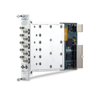
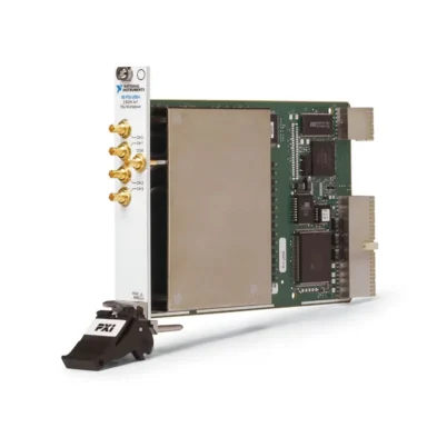
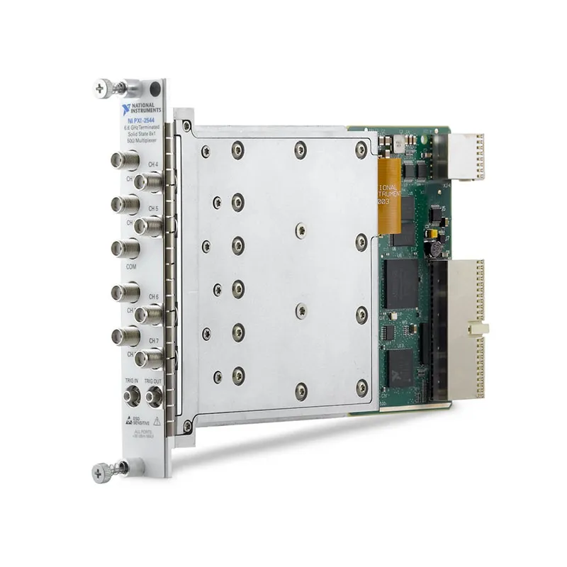
PXI-2544 6.6 GHz 8×1 Solid-State PXI RF Multiplexer
Земля PXI-2544 is a high-performance 8×1 PXI RF multiplexer switch module designed for automated RF routing through 6.6 GHz. It can connect one of eight RF channels to a common signal path, allowing multiple devices, test points or RF sources to share one analyzer or measurement instrument.
The module uses solid-state FET switching instead of conventional electromechanical relays. This architecture provides fast switching, high repeatability and freedom from mechanical contact wear. Integrated 50 Ω termination on the common path and individual channels helps maintain predictable RF performance when routes are disconnected.
Nine front-panel SMA connectors provide direct connections to RF instruments and devices under test. Separate SMB trigger connectors support synchronization with other PXI instruments and automated test events.
Key Features of the PXI-2544
- 8×1 terminated RF multiplexer topology
- 10 MHz to 6.6 GHz operating frequency range
- 50 Ω nominal characteristic impedance
- Solid-state FET switching technology
- Fast 1 ms typical switching time
- No mechanical relay-contact wear
- Integrated termination on every channel and the common path
- +30 dBm maximum safe continuous RF power with chassis power on
- +20 dBm maximum safe continuous RF power with chassis power off
- ±8 V maximum safe DC input voltage
- Less than 7.2 dB specified insertion loss through 6.6 GHz
- Greater than 61 dB specified CH-to-COM isolation through 6.6 GHz
- Greater than 56 dB specified channel-to-channel isolation through 6.6 GHz
- Less than 10 ps typical channel-to-channel skew
- 1100 ps typical propagation delay
- High RF linearity
- Nine female SMA signal connectors
- Two female SMB trigger connectors
- PXI backplane and front-panel triggering
- NI-SWITCH software support
- NI Switch Executive compatibility
- Single-slot 3U PXI module
PXI-2544 Technical Specifications
| Product Model | PXI-2544 |
|---|---|
| Part Number | 778572-44 |
| Product Type | PXI RF multiplexer switch module |
| Topology | Terminated 8×1 multiplexer |
| Number of Input Channels | 8 |
| Common Connections | 1 |
| Minimum Input Frequency | 10 MHz |
| Максимальная частота | 6.6 GHz |
| Characteristic Impedance | 50 Ω nominal |
| Signal Coupling | AC |
| Switch Type | Solid-state FET |
| Maximum Safe DC Input Voltage | ±8 V |
| Maximum Continuous RF Power, Chassis On | +30 dBm |
| Maximum Continuous RF Power, Chassis Off | +20 dBm |
| Insertion Loss through 2.4 GHz | Less than 4.5 dB; less than 3.2 dB typical |
| Insertion Loss through 6 GHz | Less than 6.3 dB; less than 5.2 dB typical |
| Insertion Loss through 6.6 GHz | Less than 7.2 dB; less than 6.0 dB typical |
| VSWR through 3.5 GHz | Less than 1.9; less than 1.5 typical |
| VSWR from 3.5 GHz through 6 GHz | Less than 1.9; less than 1.4 typical |
| VSWR from 6 GHz through 6.6 GHz | Less than 2.2; less than 1.6 typical |
| CH-to-COM Isolation through 2.4 GHz | Greater than 77 dB; greater than 95 dB typical |
| CH-to-COM Isolation through 6 GHz | Greater than 65 dB; greater than 77 dB typical |
| CH-to-COM Isolation through 6.6 GHz | Greater than 61 dB; greater than 72 dB typical |
| Channel-to-Channel Isolation through 6.6 GHz | Greater than 56 dB; greater than 76 dB typical |
| Typical Channel-to-Channel Skew | Less than 10 ps |
| Typical Propagation Delay | 1100 ps |
| Input 1 dB Compression | Greater than 27 dBm minimum; greater than 32 dBm typical |
| Typical Input IP2 | Greater than +91 dBm |
| Typical Input IP3 | Greater than +56 dBm |
| Typical Switching Time | 1 ms |
| Maximum Switching Time | 3.3 ms |
| Input Trigger Sources | PXI trigger lines 0 through 7 and front-panel trigger input |
| Minimum Trigger Pulse Width | 150 ns |
| Output Trigger Destinations | PXI trigger lines 0 through 7 and front-panel trigger output |
| Signal Connectors | 9 female SMA jacks |
| Trigger Connectors | 2 female SMB jacks |
| Поддержка программного обеспечения | NI-SWITCH and NI Switch Executive |
| Operating Temperature | 0°C to 55°C |
| Dimensions | 21.6 cm × 2.0 cm × 13.0 cm |
| Weight | 538 g |
| Module Format | 3U, single-slot PXI module |
| Life-Cycle Status | Discontinued |
| PXI Express Alternative | PXIe-2544, part number 780587-44 |
PXI-2544 Part Number and Connection Accessories
| Item | Part Number or Type | Описание |
|---|---|---|
| PXI-2544 | 778572-44 | 6.6 GHz, 50 Ω, solid-state 8×1 PXI RF multiplexer |
| PXIe-2544 | 780587-44 | PXI Express version of the 6.6 GHz terminated RF multiplexer |
| RF Signal Cable | 50 Ω SMA-to-SMA | Connects the switch to RF generators, analyzers and SMA-equipped fixtures |
| Trigger Cable | SMB-to-SMB | Connects the front-panel trigger input or output to compatible instruments |
| RF Adapter | SMA-to-N-Type, BNC or other required interface | Connects the SMA switch ports to instruments using different RF connectors |
| External Attenuator or DC Block | Application-specific | Protects the switch and establishes the required RF level or DC isolation |
The PXI-2544 uses female SMA connectors for all eight channels and the common path. Select 50 Ω cables and adapters with bandwidth, power and VSWR performance appropriate for the complete 6.6 GHz signal path.
8×1 Terminated Multiplexer Architecture
The PXI-2544 connects one of eight RF channels to a single common port. In measurement applications, the eight channels can be connected to different device-under-test points while the common port connects to one analyzer.
The topology can also be used in the opposite direction to distribute one RF source to one of eight destinations. Although the signal path is electrically usable in either direction, route names should clearly identify the intended source and destination.
Integrated Channel Termination
Every channel and the common path include termination to help maintain a controlled 50 Ω environment when a route is not selected. Termination reduces unterminated branches that could otherwise cause signal reflections or unpredictable RF loading.
The published RF specifications assume that unused front-panel connectors are terminated with 50 Ω loads. For the most representative performance, install suitable terminations on every unused connection.
10 MHz to 6.6 GHz Frequency Range
The multiplexer routes AC-coupled signals from 10 MHz through 6.6 GHz. This range supports intermediate-frequency paths, RF generators, vector signal analyzers, spectrum analyzers and many wireless test applications.
The PXI-2544 is not intended for switching DC or very-low-frequency signals because the FET signal path is AC coupled. Choose a DC-capable relay switch when the routed signal extends below 10 MHz or includes a required DC component.
Solid-State FET Switching
The PXI-2544 uses solid-state FET switches instead of electromechanical relay contacts. FET technology provides fast, repeatable switching without mechanical contact wear.
This architecture is useful in production systems and long-duration tests requiring a large number of switching operations. It also avoids the contact-bounce behavior associated with mechanical relays.
Solid-state switches have different characteristics from electromechanical relays, including insertion loss, isolation, compression and DC limitations. Evaluate these parameters against the signal being routed.
Fast Switching Performance
The typical switching time is 1 ms, with a specified maximum of 3.3 ms. Fast operation helps reduce route-change delays in automated multichannel RF tests.
Complete test settling time can be longer because the connected generator, analyzer or device under test may need additional time after a route changes.
RF Insertion Loss
Insertion loss increases as signal frequency rises. The PXI-2544 specifies less than 4.5 dB through 2.4 GHz, less than 6.3 dB through 6 GHz and less than 7.2 dB through 6.6 GHz.
Typical insertion loss is lower than the maximum specification, reaching less than 6 dB at 6.6 GHz. External cable, adapter and fixture losses must be added to the module loss when calculating the delivered signal level.
Apply path-loss compensation in the test software when accurate RF power measurements are required.
Insertion-Loss Flatness
The module provides controlled insertion-loss variation over smaller measurement bandwidths. Typical flatness remains below 0.30 dB across a 200 MHz span from 10 MHz to 5 GHz and below 0.47 dB across a 200 MHz span from 6 GHz to 6.6 GHz.
Flatness is important when routing modulated signals because uneven path response across the occupied bandwidth can affect amplitude accuracy and modulation quality.
VSWR and Impedance Matching
The PXI-2544 maintains a nominal 50 Ω characteristic impedance. Specified VSWR remains below 1.9 through 6 GHz and below 2.2 from 6 GHz through 6.6 GHz.
System VSWR also depends on cables, adapters, terminations and connected instruments. Use high-quality RF components and inspect SMA connectors for contamination or mechanical damage.
CH-to-COM Isolation
Specified isolation between a disconnected channel and the common port is greater than 77 dB through 2.4 GHz, greater than 65 dB through 6 GHz and greater than 61 dB through 6.6 GHz.
High isolation helps prevent unselected device signals from leaking into the active analyzer path. This is particularly important when the selected and unselected channels carry signals with substantially different power levels.
Channel-to-Channel Isolation
Specified isolation between channels remains greater than 56 dB through 6.6 GHz, with typical performance above 76 dB at the upper frequency limit.
External cable coupling, fixture design and poor shielding can reduce total system isolation. Keep high-power RF cables separated from low-level measurement paths.
Low Channel-to-Channel Skew
Typical channel-to-channel skew is less than 10 ps. Low skew helps maintain consistent timing when the same signal is sequentially routed through different channels.
External cable length usually contributes more skew than the switch module. Use phase-matched cables when timing or phase comparison between routes is important.
RF Linearity
The PXI-2544 provides a minimum input 1 dB compression point greater than 27 dBm and typical performance greater than 32 dBm. Typical input IP2 is greater than +91 dBm, while typical input IP3 is greater than +56 dBm.
High linearity reduces harmonics and intermodulation products generated by the switch itself. This is valuable when measuring amplifier distortion, receiver blocking or adjacent-channel performance.
RF Power Handling
With the chassis powered on, the maximum safe continuous RF input is +30 dBm. When the chassis is off, the maximum safe level falls to +20 dBm.
These are safe-input limits and do not guarantee linear operation at every frequency and power. The signal should remain within the compression and performance requirements of the application.
Remove or reduce RF power before turning off the chassis so that the applied signal does not exceed the lower unpowered limit.
Maximum Safe DC Voltage
The maximum safe DC input voltage is ±8 V. Because the RF signal path is AC coupled, the module is intended for RF rather than DC signal routing.
Use a suitable external DC block when a connected source can place an unsafe DC voltage on the switch port. Protection should be installed before the PXI-2544 input.
Front-Panel SMA Connectors
The module provides nine female SMA signal connectors: eight channel connections and one common connection. Front-mounted connectors simplify direct cabling to RF generators, analyzers and test fixtures.
Use the torque recommended for the attached SMA cable or adapter. Overtightening, cross-threading or a damaged center pin can degrade return loss and permanently damage the connector.
Front-Panel Trigger Connections
Separate TRIG IN and TRIG OUT SMB connectors support external synchronization. The trigger ports use TTL-compatible signal levels and can coordinate switch operations with external equipment.
The module also supports PXI backplane trigger lines 0 through 7, allowing switch operations to be synchronized without additional front-panel cables.
Typical PXI-2544 Applications
- Automated RF signal routing
- Wireless device production testing
- Receiver and transmitter validation
- RF analyzer input selection
- Signal-generator output distribution
- Antenna-path selection
- Multiband communications testing
- RF component characterization
- Тестирование полупроводниковых ВЧ-устройств
- Research and laboratory automation
- High-cycle RF switching
- Parallel fixture and DUT testing
RF Analyzer Input Selection
The eight channels can connect to separate DUT outputs while the common port connects to a spectrum analyzer or vector signal analyzer. Test software selects the channel required for each measurement.
This arrangement allows one analyzer to test multiple signal paths, reducing instrument count and eliminating manual cable changes.
RF Source Distribution
The common port can connect to an RF signal generator while the eight channels connect to different DUT inputs or fixtures. The PXI-2544 then selects which destination receives the signal.
Only one channel should be connected to the common path at a time in the standard 8×1 topology. The test application should use route exclusions to prevent invalid combinations.
Wireless Production Testing
The solid-state architecture is well suited to production systems requiring frequent switching. Automated software can change routes, configure instruments, collect results and determine pass or fail without operator recabling.
Path-loss correction should be stored for every channel because SMA cable and switch losses can vary slightly between routes.
Receiver Testing
The PXI-2544 can route a controlled RF source to multiple receivers or receiver inputs. Tests can include sensitivity, channel selection, blocking, gain and functional-response measurements.
When measuring weak receiver signals, verify that leakage from inactive channels remains below the required test threshold.
RF Semiconductor Testing
The multiplexer can select among multiple RFIC ports, devices or load-board connections. High linearity helps minimize distortion introduced by the routing path.
Protect the PXI-2544 against static discharge, excessive DC voltage and signals above its safe-input limits when connecting semiconductor fixtures.
NI-SWITCH Software Support
The PXI-2544 is controlled through the NI-SWITCH instrument driver. NI-SWITCH provides functions for initializing the module, connecting channels to the common port, disconnecting routes, creating scan lists and configuring triggers.
The driver supports LabVIEW, LabWindows/CVI and compatible text-based programming environments. Verify driver and operating-system compatibility when installing a discontinued PXI-2544 in a newer system.
NI Switch Executive Integration
NI Switch Executive allows developers to assign meaningful names to physical switch ports and routes. Test applications can request named connections rather than controlling the switch with raw channel identifiers.
Named routes simplify systems containing multiple RF switches and help prevent conflicting or invalid signal connections.
PXI-2544 Troubleshooting
The PXI-2544 is not detected in NI MAX
Confirm that the module is fully installed in a compatible PXI slot. Check chassis power, controller communication and NI-SWITCH installation, then refresh the hardware list in NI Measurement & Automation Explorer.
No RF signal passes through the selected channel
Verify that the intended channel is connected to COM in software. Check the SMA cables, source output, analyzer settings and external fixture. Confirm that the signal frequency is at least 10 MHz.
The signal level is lower than expected
Include the PXI-2544 insertion loss, external cable loss and adapter loss in the power calculation. Insertion loss increases as the routed frequency approaches 6.6 GHz.
The measured level changes between channels
Different cables and fixtures can produce route-to-route loss variation. Characterize every signal path and apply an individual correction value for each channel.
There are excessive reflections
Install 50 Ω terminations on unused connectors and verify that all cables, adapters and instruments use a 50 Ω interface. Inspect the SMA connectors for damage or contamination.
Isolation is lower than expected
Check for coupling between external cables and fixture traces. Separate high-power and low-level paths, improve shielding and verify that no unintended switch route is active.
The module does not respond to a front-panel trigger
Verify the TRIG IN cable, signal level, polarity and pulse width. Confirm that the module is armed before the trigger arrives and that the application selected the front-panel trigger source.
The switch does not respond to a PXI trigger
Check the selected PXI trigger line and ensure that another instrument is correctly driving it. Confirm that no trigger-line conflict exists within the chassis.
The module becomes hot during operation
Confirm that chassis airflow is unobstructed and that the fan setting is appropriate. Check the ambient temperature and leave empty-slot filler panels installed where required for correct cooling.
The switch was exposed to RF while the chassis was off
Verify that the applied power did not exceed +20 dBm. If the signal was higher, test insertion loss, isolation and switching operation before returning the module to service.
PXI-2544 Comparison with Similar RF Multiplexers
| Модель | Primary Configuration | Best Suited For |
|---|---|---|
| PXI-2542 | 6.6 GHz, four terminated 2×1 multiplexers | Several independent two-way RF switching paths |
| PXI-2543 | 6.6 GHz, two terminated 4×1 multiplexers | Two independent four-channel RF groups |
| PXI-2544 | 6.6 GHz, one terminated 8×1 multiplexer | Routing eight RF channels to one common port |
| PXI-2545 | High-frequency RF multiplexer configuration | Applications requiring alternative topology or frequency performance |
| PXIe-2544 | 6.6 GHz, terminated 8×1 PXI Express multiplexer | PXI Express systems requiring solid-state RF routing |
PXI-2544 vs PXI-2542
The PXI-2544 provides one 8×1 multiplexer, while the PXI-2542 provides four separate 2×1 multiplexers. Both use solid-state switching and support frequencies through 6.6 GHz.
Choose the PXI-2544 when eight channels must share one common instrument. Choose the PXI-2542 when the system requires four independently controlled two-way switches.
PXI-2544 vs PXI-2543
The PXI-2543 provides two independent 4×1 multiplexers, while the PXI-2544 combines eight channels into one 8×1 multiplexer.
Select the PXI-2543 for two separate RF routing groups. Select the PXI-2544 when all eight channels must connect to the same common path.
PXI-2544 vs PXIe-2544
The PXI-2544 and PXIe-2544 share the same primary 6.6 GHz, 50 Ω, terminated 8×1 solid-state RF multiplexer architecture. Their principal difference is the chassis interface.
The PXI-2544 is part number 778572-44, while the PXIe-2544 is part number 780587-44. Confirm the chassis slot type and installed NI-SWITCH version before selecting a replacement.
Solid-State vs Electromechanical RF Switching
The PXI-2544 solid-state architecture provides fast switching and does not have mechanical relay-contact wear. This is beneficial in high-cycle production testing.
Electromechanical RF switches may provide lower insertion loss, broader DC capability or different power handling. Select the switching technology according to operating frequency, signal level, required isolation, switching speed and expected cycle count.
Recommended Related Products
- PXI-2542 Quad 2×1 Solid-State RF Multiplexer
- PXI-2543 Dual 4×1 Solid-State RF Multiplexer
- PXIe-2544 8×1 Solid-State RF Multiplexer
- PXI-2545 RF Multiplexer Switch Module
- PXI-2546 RF Multiplexer Switch Module
- PXI-2547 RF Multiplexer Switch Module
- PXI-2598 RF Multiplexer Switch Module
- View More NI PXI and PXI Express Modules
Selecting the Right RF Multiplexer
Choose the PXI-2544 when an existing PXI system requires eight RF channels to share one common connection, frequencies through 6.6 GHz and high-cycle solid-state switching.
Select the PXI-2542 when four independent 2×1 paths are needed, or the PXI-2543 when two independent 4×1 groups better match the fixture architecture. Use the PXIe-2544 in a compatible PXI Express system.
Why Choose the PXI-2544?
- Routes eight RF channels to one common port
- Supports frequencies from 10 MHz to 6.6 GHz
- Maintains nominal 50 Ω signal paths
- Terminates unused channels and the common connection
- Uses fast solid-state FET switching
- Avoids mechanical relay-contact wear
- Provides high isolation and RF linearity
- Uses convenient front-panel SMA connections
- Supports front-panel and PXI backplane triggering
- Integrates with NI-SWITCH and NI Switch Executive
Frequently Asked Questions
What is the PXI-2544?
The PXI-2544 is a 6.6 GHz, 50 Ω, solid-state 8×1 PXI RF multiplexer used to connect one of eight channels to a common RF path.
What is the frequency range?
The specified operating frequency range is 10 MHz to 6.6 GHz.
Does the PXI-2544 support DC signals?
No. The signal path is AC coupled and has a 10 MHz minimum input frequency. It should not be selected for DC or low-frequency routing.
Which switching technology does it use?
The module uses solid-state FET switches rather than electromechanical relay contacts.
Are unused channels terminated?
Yes. The PXI-2544 provides termination on the common path and every channel. Official RF performance assumes unused front-panel ports are properly terminated.
What is the maximum safe RF power?
The maximum safe continuous RF power is +30 dBm with the chassis powered on and +20 dBm with the chassis powered off.
What is the maximum safe DC input voltage?
The maximum safe DC input voltage is ±8 V.
What connectors does the PXI-2544 use?
It provides nine female SMA signal connectors and two female SMB trigger connectors.
What is the typical switching time?
The typical switching time is 1 ms, with a specified maximum of 3.3 ms.
Which software controls the PXI-2544?
The module is controlled with NI-SWITCH and can use named routes through NI Switch Executive.
What is the PXI-2544 part number?
The standard NI part number is 778572-44.
Is the PXI-2544 still available from NI?
No. NI identifies the PXI-2544 as no longer available. Used, refurbished or surplus modules may remain available.
What is the PXI Express alternative?
The PXIe-2544, part number 780587-44, provides the corresponding 6.6 GHz terminated 8×1 multiplexer for compatible PXI Express systems.
What should be checked before purchasing a used PXI-2544?
Verify every CH-to-COM route, insertion loss at multiple frequencies, isolation, trigger operation and SMA connector condition. Testing only low-frequency continuity is not sufficient for a 6.6 GHz RF switch.
Request a Quote for the PXI-2544
Contact us for current availability, test condition and project pricing for the PXI-2544 6.6 GHz 8×1 Solid-State PXI RF Multiplexer. We can also help identify compatible SMA cables, terminations, PXI chassis and related RF switch modules.















