






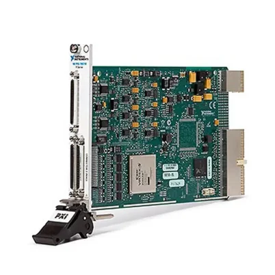
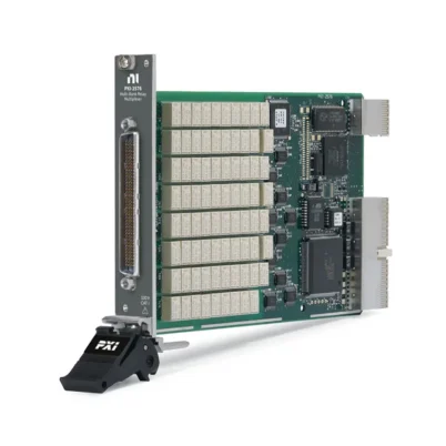
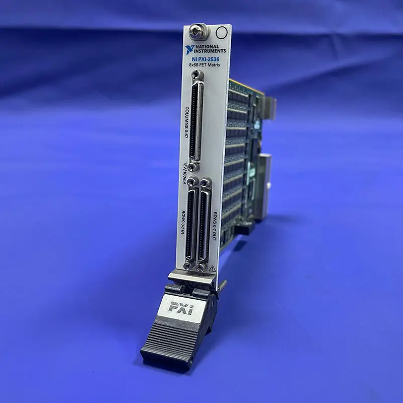
PXI-2536 8×68 High-Density Matrix Switch Module
Земля PXI-2536 is a high-density, one-wire PXI matrix switch module with an 8×68 topology and 544 crosspoints. It is designed for automated routing of low-power DC signals in semiconductor, printed circuit board and electronic device validation systems.
The module uses field-effect transistor relays and supports switching speeds up to 50,000 crosspoints per second. Its solid-state architecture eliminates mechanical contact wear and supports high-throughput production testing.
Key Features of the PXI-2536
- 8×68 one-wire matrix topology
- 544 independently controlled crosspoints
- Field-effect transistor relay technology
- Up to 50,000 crosspoint operations per second
- 12 V maximum DC switching voltage
- 100 mA maximum switching current
- 1.2 W maximum switching power per channel
- Greater than 1 MHz typical single-crosspoint bandwidth
- 10 µV typical offset voltage
- Hardware triggering for deterministic scanning
- Onboard relay-operation counting
- PXI Hybrid bus connector
- NI-SWITCH and NI Switch Executive support
PXI-2536 Technical Specifications
| Product Model | PXI-2536 |
|---|---|
| Part Number | 778572-36 |
| Product Type | PXI Matrix Switch Module |
| Matrix Topology | 8×68, one-wire |
| Matrix Rows | 8 |
| Matrix Columns | 68 |
| Crosspoints | 544 |
| Тип реле | Field-effect transistor |
| Maximum Scan Rate | 50,000 crosspoints/s |
| Typical FET Operating Time | 12 µs |
| Maximum Switching Voltage | 12 VDC or 8 VAC |
| Maximum Switching Current | 100 mA |
| Maximum Switching Power | 1.2 W per channel, resistive |
| Typical Path Resistance | 10 Ω, row to column |
| Maximum Path Resistance | 15.5 Ω, row to column |
| Typical Offset Voltage | 10 µV |
| Typical Bandwidth | Greater than 1 MHz for one crosspoint |
| Powered-On Overvoltage Protection | ±36 VDC |
| Powered-Off Overvoltage Protection | ±40 VDC |
| Front Connectors | 4 × 68-pin VHDCI |
| Bus Connector | PXI Hybrid |
PXI-2536 Part Number and Accessories
| Item | Part Number | Описание |
|---|---|---|
| PXI-2536 | 778572-36 | 8×68, 544-crosspoint FET matrix switch module |
| TBX-68 | 777141-01 | 68-pin male SCSI connector block |
| CB-68LP | 777145-01 | Low-profile 68-pin connector block |
| CB-68LPR | 777145-02 | Rack-mountable 68-pin connector block |
| SHC68-C68-S | 186380-02 | 2 m shielded cable for PXI switch connections |
| SHC68-68 | 191945-01 | 1 m shielded 68-pin cable |
| SHC68-68 | 191945-02 | 2 m shielded 68-pin cable |
Use shielded cables and accessories to maintain the specified electromagnetic compatibility performance. Accessory requirements depend on cable length, connector block location and test fixture design.
8×68 Matrix Architecture
The PXI-2536 provides eight rows and 68 columns, creating 544 independently controlled crosspoints. Any row can be connected to one or more columns through software commands or a predefined scan list.
This topology allows up to eight measurement or stimulus paths to access a large number of device-under-test connections without manual cable changes.
One-Wire Signal Routing
The module uses a one-wire matrix topology. Each crosspoint switches one signal conductor between a row and a column.
A separate return or ground connection must be provided through the test fixture or system wiring. The PXI-2536 is therefore intended for compatible low-power signals sharing an appropriate reference.
544 Independently Controlled Crosspoints
Each of the 544 crosspoints can be controlled independently. Multiple routes can be closed simultaneously to connect several instruments, distribute a common signal or create application-specific switching paths.
Before closing multiple routes, verify that the resulting connections will not short independent sources or exceed the voltage, current and power ratings.
FET Relay Technology
The PXI-2536 uses FET relays rather than conventional mechanical contacts. This provides fast switching and eliminates mechanical relay contact wear when the module operates within its specified limits.
FET switching is particularly useful in production systems that execute a large number of repetitive switching operations.
High-Speed Matrix Scanning
The PXI-2536 supports switching speeds up to 50,000 crosspoints per second. Its typical FET operation time is approximately 12 µs.
High-speed scanning can significantly reduce test duration when many device-under-test points must be measured sequentially.
Hardware-Triggered Operation
Hardware triggering allows the matrix to advance through a scan list without waiting for individual host-computer commands. This provides more deterministic switching timing.
The switch can be coordinated with a digital multimeter, source measurement unit, digitizer or other PXI instrument to improve automated test throughput.
Low-Power DC Signal Routing
The module supports switching voltages up to 12 VDC, currents up to 100 mA and resistive switching power up to 1.2 W per channel.
The PXI-2536 should not be used for high-voltage, high-current or power switching applications. Select a switch module with suitable electromechanical relays when higher ratings are required.
Path Resistance Considerations
The typical row-to-column path resistance is approximately 10 Ω and can reach 15.5 Ω. This resistance can produce a voltage drop when current flows through the switch path.
The PXI-2536 is best suited to high-impedance measurement instruments and other low-current signal-routing applications.
Signal Bandwidth and Crosstalk
A single crosspoint provides a typical bandwidth greater than 1 MHz in a 50 Ω test configuration. Actual bandwidth depends on cable length, fixture design, connected instruments and the number of active routes.
Unused routes should remain open, and shielded cabling should be used to reduce crosstalk between sensitive signals.
Onboard Relay Counting
The module includes onboard relay-operation counting for monitoring switch usage. Operation counts can help confirm test execution, identify heavily used routes and maintain system records.
Although FET switches do not have mechanical contacts, usage tracking remains useful in production and validation systems.
Типичные применения
- Semiconductor device validation
- Printed circuit board testing
- Integrated circuit production testing
- Continuity and resistance testing
- Low-power DC signal routing
- Electronic component characterization
- Measurement instrument sharing
- Automated functional testing
- Design verification testing
- Production test fixture automation
Системы тестирования полупроводников
The 8×68 topology allows several measurement or stimulus paths to connect to a large number of semiconductor pins. Fast FET switching helps reduce the time required for repetitive validation sequences.
The module can route suitable low-power DC signals from source measurement units, digital multimeters and other automated test instruments.
PCB Functional Testing
In PCB testing, the PXI-2536 can connect multiple instruments to selected nodes in a test fixture. Software selects the required crosspoints for each stage of the functional test.
This reduces manual wiring and allows the same instrumentation to be reused across many test points.
NI-SWITCH Driver Support
The PXI-2536 is controlled through the NI-SWITCH driver. The driver provides functions for connecting routes, disconnecting routes, creating scan lists, processing triggers and monitoring switch operations.
Automated applications can be developed using LabVIEW, C, C#, Python and other supported programming environments.
NI Switch Executive Integration
NI Switch Executive provides route-based management for complex switching systems. Developers can assign meaningful names to signal routes instead of controlling individual crosspoints throughout the test code.
This approach simplifies system maintenance and helps reduce routing errors in automated test applications containing multiple switch modules.
Интеграция систем PXI
The PXI-2536 uses a PXI Hybrid connector and requires a compatible PXI or PXI Express hybrid chassis slot. The controller and software environment must support the NI-SWITCH driver.
Visit the NI PXI Modules category to explore related switch and measurement hardware.
Troubleshooting the PXI-2536
The module is not detected
Confirm that the PXI-2536 is installed in a compatible PXI Hybrid slot. Check the chassis controller, PXI Platform Services and NI-SWITCH driver installation.
A configured route does not close
Verify the row and column names, matrix topology and route syntax. Check whether the requested route conflicts with an existing connection.
The measured signal has an unexpected voltage drop
Include the module’s path resistance in the circuit calculation. Check the signal current, cable resistance, connector contacts and fixture wiring.
The signal appears on the wrong test point
Verify the connector pinout, cable orientation, column assignment and fixture wiring. Test each route for continuity before connecting sensitive equipment.
A floating measurement source produces incorrect readings
Ensure that the floating source has an appropriate reference to chassis or earth ground. An unsuitable floating connection can interact with the FET protection circuitry and produce incorrect results.
Automated scanning is slower than expected
Review instrument measurement time, software delays, trigger configuration and scan sequencing. Hardware triggering can reduce host-command overhead.
PXI-2536 Comparison
| Модель | Topology | Crosspoints | Тип реле | Primary Use |
|---|---|---|---|---|
| PXI-2536 | 8×68 | 544 | FET | Eight-row, low-power DC routing |
| PXI-2535 | 4×136 | 544 | FET | Fewer rows with more columns |
| PXI-2534 | 8×32 | 256 | Solid-state | Lower-density eight-row routing |
| PXI-2533 | 4×64 | 256 | Solid-state | Four-row matrix applications |
| PXI-2531 | Multiple configurations | Up to 512 | Reed relay | Flexible signal-routing topologies |
Recommended Related Products
- PXI-2535 – 4×136 FET matrix switch with the same 544-crosspoint capacity
- PXI-2534 – 8×32 solid-state matrix switch for lower channel-count systems
- PXI-2533 – 4×64 matrix switch for automated signal routing
- PXI-2531 – configurable reed-relay matrix switch for flexible topologies
- PXIe-4080 – digital multimeter for automated voltage, current and resistance measurements
Selecting the PXI-2536
Choose the PXI-2536 when the test system requires up to eight matrix rows to access 68 columns and all routed signals remain within the module’s low-power DC ratings.
If fewer instrument rows and more device-under-test columns are required, consider the PXI-2535. Select a higher-rated electromechanical or reed-relay module when routing higher voltage, current or power.
PXI-2536 vs PXI-2535
The PXI-2536 and PXI-2535 both provide 544 FET crosspoints, switching speeds up to 50,000 crosspoints per second and low-power DC signal routing.
The primary difference is topology. The PXI-2536 uses an 8×68 matrix, while the PXI-2535 uses a 4×136 matrix. The correct model depends on the required number of instrument rows and device-under-test columns.
Why Choose the PXI-2536?
- 544 crosspoints in one PXI module
- 8×68 topology for multiple instrument paths
- Fast FET switching up to 50,000 crosspoints/s
- No mechanical relay contact wear
- Hardware-triggered deterministic scanning
- Low offset voltage for precision DC routing
- NI-SWITCH and Switch Executive integration
Frequently Asked Questions
What is the PXI-2536 used for?
The PXI-2536 routes low-power DC signals between multiple instruments and device-under-test points in semiconductor, PCB and automated production test systems.
What is the PXI-2536 matrix configuration?
It provides an 8×68 one-wire matrix with 544 crosspoints.
Which relay technology does it use?
The PXI-2536 uses field-effect transistor relays for fast solid-state switching without mechanical contact wear.
What is the maximum switching speed?
The module supports switching rates up to 50,000 crosspoints per second.
What voltage and current can it switch?
The PXI-2536 supports up to 12 VDC, 100 mA and 1.2 W of resistive switching power per channel.
Can the PXI-2536 switch high-power loads?
No. It is designed for low-power signal routing and should not be used for high-voltage or high-current loads.
Does the PXI-2536 support hardware triggering?
Yes. Hardware triggering enables deterministic scanning and synchronization with compatible test instruments.
What is the difference between the PXI-2536 and PXI-2535?
The PXI-2536 uses an 8×68 topology, while the PXI-2535 uses a 4×136 topology. Both provide 544 FET crosspoints.
What is the PXI-2536 part number?
The standard NI part number for the PXI-2536 is 778572-36.
Request a Quote for the PXI-2536
Contact us for current availability, lead time and project pricing for the PXI-2536 Matrix Switch Module. We can also help confirm compatible cables, connector blocks, PXI chassis and related switch modules for your test system.















