






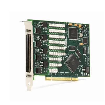
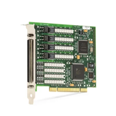
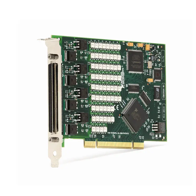
PCI-6513 64-Channel Bank-Isolated Sink Digital Output Device
Земля PCI-6513 is an industrial digital output device designed for computer-based automation, production testing and industrial actuator control. It provides 64 optically isolated sinking outputs organized into eight independently powered banks of eight channels.
The device switches external DC loads operating at up to 30 VDC. Programmable power-up states and digital I/O watchdogs allow engineers to define safe output conditions during computer startup, application failure or communication loss.
Key Features of the PCI-6513
- 64 dedicated digital output channels
- Eight isolated banks with eight lines per bank
- Sinking digital output architecture
- 30 VDC maximum switching voltage
- External 5 VDC to 30 VDC load supply
- Up to 475 mA on one active line per bank at 25°C
- Up to 125 mA per line with all eight bank lines active at 25°C
- Current capability derated according to temperature and channel usage
- 30 VDC bank-to-bank and bank-to-bus isolation
- Optically isolated output channels
- Programmable power-up output states
- Configurable watchdog safe states
- Self-resetting overcurrent fuse on each output port
- 80 µs typical propagation delay
- 100-pin keyed female SCSI connector
- Conventional PCI computer interface
- NI-DAQmx software support
PCI-6513 Technical Specifications
| Product Model | PCI-6513 |
|---|---|
| Part Number | 778970-01 |
| Product Type | Bank-isolated industrial digital output device |
| Total Digital Channels | 64 |
| Digital Input Channels | 0 |
| Digital Output Channels | 64 |
| Тип вывода | Sinking |
| Signaling Type | Single-ended |
| Number of Banks | 8 |
| Channels per Bank | 8 |
| Channel Isolation | Optical isolation |
| Common-Mode Isolation | 30 VDC, bank-to-bank and bank-to-bus |
| Maximum Switching Voltage | 30 VDC |
| External Load-Supply Range | 5 VDC to 30 VDC |
| Maximum Current, All Eight Lines Active at 25°C | 125 mA per line |
| Maximum Current, One Line per Bank at 25°C | 475 mA |
| Maximum Sinking-Output Voltage Drop at 100 mA | 1.1 V |
| Maximum Sinking-Output Voltage Drop at 200 mA | 1.3 V |
| Maximum Sinking-Output Voltage Drop at 350 mA | 1.6 V |
| Typical Propagation Delay | 80 µs with 100 Ω load |
| Default Power-On State | Logic 0, output open |
| Programmable Power-Up States | Logic 0 or logic 1 |
| Power-Up-State Response Time | 400 ms |
| Overcurrent Protection | Self-resetting fuse on each output port |
| Data Transfers | Interrupts and programmed I/O |
| I/O Connector | 100-pin keyed female SCSI |
| Computer Bus | PCI |
| PCI Power Consumption at +5 V | 250 mA typical |
| PCI Power Consumption at +3.3 V | 300 mA typical |
| Dimensions | 18.1 × 12.6 cm |
| Weight | 70.9 g |
| Operating Temperature | 0°C to 55°C |
| Storage Temperature | −20°C to 70°C |
| Operating Humidity | 10% to 90%, noncondensing |
| Storage Humidity | 5% to 95%, noncondensing |
| Maximum Operating Altitude | 2,000 m |
| Software Driver | НИ-DAQmx |
PCI-6513 Output-Current Derating
| Ambient Temperature | All Eight Lines Active per Bank | One Active Line per Bank |
|---|---|---|
| Up to 25°C | 125 mA per line | 475 mA |
| Up to 35°C | 125 mA per line | 425 mA |
| Up to 45°C | 115 mA per line | 375 mA |
| Up to 55°C | 100 mA per line | 325 mA |
These limits apply at a 100% duty cycle under the specified operating conditions. Actual current capability depends on ambient temperature, airflow, output voltage, number of active channels, duty cycle and enclosure cooling.
PCI-6513 Part Number and Accessories
| Item | Part Number | Описание |
|---|---|---|
| PCI-6513 | 778970-01 | 64-channel, 30 V bank-isolated sinking digital output device |
| SH100M-100M Flex Cable | 185095-01 | 1 m shielded 100-pin cable assembly |
| R100M-50F-50F Cable | 182762-02 | 2 m ribbon cable dividing the 100-pin interface into two 50-pin connectors |
| SCB-100A Connector Block | 785024-01 | Shielded, noise-rejecting 100-pin I/O connector block |
| CB-50 Connector Block | 776164-90 | 50-pin DIN-rail-mountable connector block without cable |
| CB-50LP Connector Block | 777101-01 | Low-cost unshielded 50-pin I/O connector block |
Use the SH100M-100M cable with the SCB-100A when a shielded 100-pin connection is required. The R100M-50F-50F cable can connect the device to two CB-50 or CB-50LP blocks for accessible field wiring.
64 Dedicated Digital Outputs
The PCI-6513 provides 64 dedicated digital output lines. Unlike bidirectional digital devices, every channel is designed specifically for controlling an external load.
The large channel count supports centralized control of relays, solenoids, lamps, valves, indicators and other industrial DC loads from one PCI slot.
Eight Isolated Output Banks
The 64 output channels are divided into eight banks of eight lines. Each bank has its own power and ground connections, allowing groups of channels to operate from different compatible external supplies.
Isolation is provided between banks and between the field wiring and computer bus. This helps reduce ground-loop current and prevents one field circuit from sharing a direct ground path with every other output group.
30 VDC Bank Isolation
The PCI-6513 provides 30 VDC common-mode isolation between output banks and between the banks and computer bus. It is designed for low-voltage industrial control circuits.
The device is not intended to switch mains power directly. Use an appropriately rated interposing relay, contactor or solid-state relay when controlling higher-voltage equipment.
Sinking Digital Outputs
A sinking output switches the load current toward the bank ground. The positive side of the load is connected to the external DC supply, while the other side is connected to a PCI-6513 output channel.
When the output is activated, the channel provides a current path from the load to ground. This arrangement is commonly used with industrial loads designed for NPN or sinking control.
Sinking-Output Wiring
Connect an external 5 VDC to 30 VDC supply to the appropriate bank power and ground connections. Connect the load between the positive supply and the selected digital output line.
All eight channels in a bank share the associated ground and power connections. Confirm the field wiring against the official pinout before applying power.
External Power Supply Requirement
The PCI-6513 does not generate the field voltage used to energize connected loads. A separate external DC power supply is required for each output bank or group of banks.
The external supply must remain within the device voltage rating and provide sufficient current for all simultaneously active loads. Include suitable fusing and current limiting in the field circuit.
Current-Sinking Capability
At ambient temperatures up to 25°C, each output can sink as much as 125 mA when all eight lines in a bank are continuously active. If only one line in each bank is used, that line can sink as much as 475 mA.
The allowable current decreases as ambient temperature rises. Engineers must use the appropriate derated value rather than treating the highest single-line rating as available on every channel simultaneously.
Output Voltage Drop
The PCI-6513 uses a transistor output stage that introduces voltage drop while sinking load current. Maximum voltage drop is 1.1 V at 100 mA, 1.3 V at 200 mA and 1.6 V at 350 mA.
Subtract this voltage drop from the external supply voltage when determining the voltage delivered to the load. This is especially important for low-voltage loads with a narrow operating range.
Output-Power Calculation
Power dissipated in an active output depends on the sinking current and voltage drop across the output stage. Higher current, high duty cycle and simultaneous operation of many channels increase device temperature.
Maintain sufficient airflow around the PCI card and avoid exceeding the current limits shown for the applicable ambient temperature.
Self-Resetting Overcurrent Protection
Each output port includes a self-resetting fuse that helps protect the board from severe overcurrent conditions. If excessive current causes the protection circuit to trip, the affected outputs may shut down.
Remove the overload and allow the protection device to recover. A self-resetting fuse is a protective feature and should not replace correctly rated external fuses or current-limited power supplies.
Inductive Load Protection
Relays, solenoids, valves and contactors can generate a high-voltage transient when current is interrupted. Install a suitable flyback diode or other suppression component across inductive DC loads.
Locate the suppression component close to the load and select it according to the load voltage, current and required release time.
Programmable Power-Up States
The default power-on state is logic 0, which leaves the sinking output open. The PCI-6513 also allows power-up states to be programmed as logic 0 or logic 1.
This feature allows the computer to establish known output conditions during startup. The programmed state is applied within the specified power-up response period.
Power-Up-State Response Time
The specified programmable power-up-state response time is 400 ms. System designers should not assume that a configured state appears immediately when computer power is applied.
If a machine requires an immediate safety state, implement that behavior with independent external circuitry rather than depending solely on software-controlled outputs.
Digital I/O Watchdog
The PCI-6513 supports a digital I/O watchdog that monitors communication between the application and device. If the application stops servicing the watchdog, the outputs can transition to configured safe states.
The watchdog is useful for detecting software crashes, operating-system failures or stalled control loops. Safe-state behavior should be tested under realistic fault conditions before commissioning the system.
Watchdog Safe States
Each output should be assigned a state that minimizes risk when application control is lost. Depending on the connected load, the safe state may turn an actuator off, release a relay or activate a warning circuit.
The complete machine-safety strategy should include hardware emergency stops, safety relays and other independently rated protection where required.
Optical Isolation
The field outputs are optically isolated from the computer-side logic. Optical isolation reduces direct electrical coupling between the industrial wiring and the PCI bus.
This protection helps with ground-potential differences and electrical noise, but all signals must still remain within the published isolation and voltage limits.
80 µs Propagation Delay
The typical output propagation delay is 80 µs with a 100 Ω load. This is suitable for industrial on/off control, relay switching, indication and many production-test applications.
The PCI-6513 is not a hardware-timed digital waveform generator. Applications requiring precisely timed, high-speed digital patterns should use a dedicated high-speed digital I/O device.
100-Pin SCSI Connector
The PCI-6513 uses a keyed female 100-pin high-density SCSI connector. The connector carries the 64 output lines together with the bank power, ground and related connections.
Because the connector has many closely spaced pins, use a compatible NI cable and connector block rather than attempting to wire directly to the card.
SCB-100A Integration
The SCB-100A provides a shielded connector block for accessing the device signals. It is suitable when the installation requires improved shielding, organized field wiring and a single 100-pin cable.
Verify that the connector block is configured and labeled according to the PCI-6513 output-bank pinout.
CB-50 and CB-50LP Integration
The R100M-50F-50F cable divides the PCI-6513 connection into two 50-pin interfaces. These interfaces can connect to CB-50 or CB-50LP blocks.
This arrangement provides separate, accessible terminals for the two halves of the 100-pin device connector and can simplify control-cabinet wiring.
Relay and Contactor Control
The PCI-6513 can control compatible DC relay and contactor coils within its voltage and current limits. The relay contacts can then switch higher-power circuits that the PCI device cannot drive directly.
Install flyback suppression on DC coils and confirm that the coil current, including inrush, remains within the appropriate temperature-derated output limit.
Solenoid and Valve Control
Industrial solenoids and pneumatic valves can be controlled when their DC voltage and current requirements remain within specification.
Use external protection for inductive transients and verify that the selected safe state will not create unexpected machine movement during startup or a watchdog timeout.
Lamp and Indicator Control
The 64 outputs can operate panel indicators, warning lamps and compatible low-voltage signaling devices. Check cold-filament inrush current when driving incandescent lamps.
LED indicators may require an external resistor or dedicated driver depending on their electrical design.
PLC Interface Simulation
The PCI-6513 can simulate multiple sinking digital outputs in automated PLC, controller and industrial-equipment tests. Software can generate different output combinations to verify controller response.
Bank isolation allows separate groups of outputs to interface with compatible circuits using different ground references, provided the isolation limits are respected.
Production Test Fixtures
The high output count makes the PCI-6513 suitable for production fixtures that control relays, clamps, indicators, pneumatic valves and DUT operating modes.
Programmable startup and watchdog states help keep the fixture in a defined condition when the computer starts or the test application stops unexpectedly.
NI-DAQmx Software Support
The PCI-6513 is controlled with NI-DAQmx. NI-DAQmx provides functions for device configuration, digital output writes, power-up states, watchdog operation and diagnostics.
The driver supports LabVIEW and compatible C, C++, C# and other programming environments. Engineers can also use NI MAX to verify device detection and perform basic testing.
PCI Computer Integration
The PCI-6513 installs in a compatible conventional PCI slot in a desktop or industrial computer. It is not a PCI Express card.
Before ordering, confirm that the target computer has the required PCI slot, mechanical clearance, supported operating system and compatible NI-DAQmx version.
Typical PCI-6513 Applications
- Industrial actuator control
- Relay and contactor control
- Solenoid and valve control
- Indicator and warning-light control
- Production test fixtures
- PLC output simulation
- Machine-control interfaces
- Автоматизация процессов
- Environmental test systems
- Laboratory automation
- Equipment validation
- End-of-line functional testing
PCI-6513 Troubleshooting
The PCI-6513 is not detected in NI MAX
Confirm that the device is fully inserted into a compatible PCI slot. Check computer BIOS settings, NI-DAQmx installation and operating-system compatibility, then rescan for hardware in NI MAX.
An output channel does not switch the load
Verify the external DC supply, bank ground, load wiring and output command. The PCI-6513 does not internally supply the field voltage required by the load.
The output reads voltage but cannot drive current
Check the load connection and external supply. A high-impedance meter can display voltage in an improperly wired circuit even when no usable load-current path exists.
Outputs shut down when several loads activate
Calculate the total bank current and compare each channel with the temperature-derated limits. The self-resetting port fuse may activate when the output current is excessive.
The load receives less voltage than expected
Account for the voltage drop across the sinking output transistor. The drop increases with current and can reach 1.6 V at 350 mA.
The computer resets when an inductive load switches
Install suitable flyback suppression across the load. Check grounding, cable shielding, power-supply regulation and separation between field wiring and computer wiring.
The outputs enter an unexpected state during startup
Review the programmed power-up states and allow for the 400 ms response time. Verify that the application does not overwrite the desired state after initialization.
The watchdog does not place outputs in a safe state
Confirm that the watchdog is configured and started by the application. Check the expiration time and the safe-state value assigned to each output.
A channel remains off after an overload
Disconnect the excessive load and allow the self-resetting fuse to recover. Inspect the wiring for shorts and confirm that the load current remains within the specified limit.
PCI-6513 Comparison with Similar Digital I/O Devices
| Модель | Channel Configuration | Тип вывода | Best Suited For |
|---|---|---|---|
| PCI-6513 | 64 isolated outputs | Sinking | High-channel-count NPN-style industrial load control |
| PCI-6512 | 64 isolated outputs | Источники | High-channel-count PNP-style industrial load control |
| PCI-6515 | 32 isolated inputs and 32 isolated outputs | Sinking outputs | Systems requiring both status inputs and sinking control outputs |
| PCI-6517 | 32 isolated outputs | Sinking | Lower-channel-count systems using a 37-pin connector |
| PCI-6519 | 16 isolated inputs and 16 isolated outputs | Sinking outputs | Compact mixed-input and sinking-output applications |
| PXI-6513 | 64 isolated outputs | Sinking | Equivalent output function in a modular PXI chassis |
PCI-6513 vs PCI-6512
The PCI-6513 provides 64 sinking outputs, while the PCI-6512 provides 64 sourcing outputs. Both models organize the channels into eight isolated banks and use a 100-pin SCSI connector.
Choose the PCI-6513 when the load requires the control device to switch current toward ground. Choose the PCI-6512 sourcing-output device when the controller must supply positive current to the load.
PCI-6513 vs PCI-6515
The PCI-6513 provides 64 dedicated sinking outputs. The PCI-6515 divides its channels between 32 isolated inputs and 32 sinking outputs.
Select the PCI-6513 when maximum output-channel density is required. Choose the PCI-6515 isolated digital I/O device when the same card must monitor field signals and control sinking loads.
PCI-6513 vs PXI-6513
The PCI-6513 and PXI-6513 provide similar 64-channel, bank-isolated sinking-output functions. The primary difference is the host interface and mechanical format.
Choose the PCI-6513 for a compatible desktop or industrial computer with a conventional PCI slot. Choose the PXI-6513 digital output module for integration into a modular PXI chassis.
Recommended Related Products
- PCI-6512 64-Channel Sourcing Digital Output Device
- PCI-6515 32-Input 32-Sinking-Output Digital I/O Device
- PCI-6517 32-Channel Sinking Digital Output Device
- PCI-6519 Isolated Digital I/O Device
- PXI-6513 64-Channel Sinking Digital Output Module
- PCI-6528 Isolated Digital I/O Device
- View More NI PCI and USB Data Acquisition Devices
Selecting the Right Industrial Digital Output Device
Choose the PCI-6513 when the application requires 64 isolated sinking outputs, eight independently powered banks and programmable startup and watchdog states.
Select a sourcing-output model when the connected loads require PNP-style control. Choose a mixed digital I/O model when the system must both monitor input signals and operate output loads.
Why Choose the PCI-6513?
- Provides 64 dedicated industrial output channels
- Uses sinking outputs for NPN-style load control
- Divides channels into eight isolated banks
- Switches compatible loads at up to 30 VDC
- Supports programmable power-up states
- Provides configurable watchdog safe states
- Includes self-resetting overcurrent protection
- Uses a high-density 100-pin SCSI interface
- Integrates with NI-DAQmx applications
- Supports automation and production-test systems
Frequently Asked Questions
What is the PCI-6513?
The PCI-6513 is a 64-channel, bank-isolated sinking digital output device for industrial control and computer-based automation.
What is the PCI-6513 part number?
The standard NI part number for the PCI-6513 is 778970-01.
How many output channels does it provide?
The device provides 64 dedicated digital outputs organized into eight banks of eight channels.
Does the PCI-6513 provide digital inputs?
No. All 64 channels are dedicated sinking outputs.
What is a sinking output?
A sinking output completes the load-current path toward ground. The load is connected between the external positive supply and the selected output channel.
Does the PCI-6513 require an external power supply?
Yes. It does not generate the field voltage required by the loads. Connect a suitable external DC supply according to the official wiring diagram.
What is the maximum switching voltage?
The maximum switching voltage is 30 VDC.
What is the maximum output current?
At up to 25°C, one active line per bank can sink as much as 475 mA. When all eight lines in a bank are active, the limit is 125 mA per line. These values decrease at higher temperatures.
Does the PCI-6513 provide channel isolation?
The outputs are optically isolated and organized into eight banks. Common-mode isolation is rated at 30 VDC between banks and between the banks and computer bus.
What happens during computer startup?
The default output state is logic 0 or open. Users can program the power-up state of the outputs as logic 0 or logic 1.
Does the device provide a watchdog?
Yes. The digital I/O watchdog can place outputs in configured safe states if the application stops communicating with the device.
Which connector does the PCI-6513 use?
The device uses a 100-pin keyed female SCSI connector.
Which software controls the PCI-6513?
The PCI-6513 is controlled through NI-DAQmx and can be programmed with LabVIEW and compatible text-based development environments.
Request a Quote for the PCI-6513
Contact us for current availability, lead time and project pricing for the PCI-6513 64-Channel Bank-Isolated Sink Digital Output Device. We can also help identify compatible SCSI cables, connector blocks, industrial power supplies and related NI digital I/O hardware for your automation or production test system.















