






Quick Answer: Choose PXI modules by starting with the signals and test functions, then comparing channel count, signal range, sampling rate, bandwidth, resolution, accuracy, isolation, triggering, synchronization, and connector requirements. After selecting the measurement performance, verify PXI or PXIe slot compatibility, data throughput, power, cooling, drivers, operating system, and accessories. The best module is the one that meets the complete electrical and system requirement—not simply the model with the highest sample rate or resolution.
What Are PXI Modules?
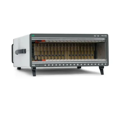
PXI модули are plug-in instruments and interfaces installed in a Шасси PXI. They provide measurement, waveform generation, power, switching, digital control, RF test, data acquisition, FPGA processing, timing, and communication functions.
A complete PXI system may combine modules from several instrument categories. For example, an automated functional tester might include a DMM, switch matrix, programmable power supply, digital I/O, waveform generator, and digitizer.
Module selection must consider both instrument performance and system integration. A module can meet the electrical specification but remain unsuitable because it requires an incompatible slot, unsupported driver, proprietary terminal block, excessive bandwidth, or more cooling than the chassis provides.
Choose PXI Modules in the Correct Order
Recommended selection process:
- List every signal and test function.
- Define ranges, channels, rates, bandwidth, accuracy, and isolation.
- Choose the appropriate instrument category and channel architecture.
- Evaluate timing, triggering, and synchronization.
- Calculate module and system data throughput.
- Verify PXI/PXIe slot, power, and cooling compatibility.
- Verify drivers, APIs, operating system, and software licenses.
- Complete the configuration with cables, terminal blocks, and calibration.
Step 1: Define the Required Test Functions
Start from the device under test rather than a module model. List everything the system must measure, generate, switch, control, or communicate.
MeasureVoltage, current, resistance, frequency, temperature, strain, vibration, RF, digital or protocol data.
GenerateAnalog waveforms, RF signals, digital patterns, DC voltage, current, power or simulated sensors.
RouteMultiplex, matrix-switch, isolate, insert faults, or connect test points to shared instruments.
CommunicateCAN, LIN, FlexRay, serial, Ethernet, avionics, high-speed serial, GPIB or custom interfaces.
Describe whether functions operate sequentially or simultaneously, whether several DUTs are tested in parallel, and whether the module must process signals onboard.
Step 2: Define the Electrical Specifications
Signal Range
Specify normal, minimum, maximum, transient, and common-mode levels. Include source impedance, load impedance, coupling, grounding, and protection. Choose the narrowest practical measurement range that safely covers the signal.
Channel Count
Separate total channel count from simultaneous channel count. A multiplexed module shares one converter across several inputs, while a simultaneous-sampling module uses separate conversion paths for time-correlated measurements.
Частота дискретизации
Confirm whether the published rate is per channel, aggregate, simultaneous, or available only under specific configurations. Include continuous and finite-record requirements.
Analog Bandwidth
Analog bandwidth defines the frequency range passed by the input or output path. It is not the same as sample rate. High-speed waveform capture requires both sufficient bandwidth and sufficient real-time sampling.
Resolution and Accuracy
Resolution describes the smallest digital step, while accuracy describes closeness to the true value. Compare gain error, offset, noise, linearity, temperature coefficient, range, stability, and calibration uncertainty rather than ADC bits alone.
Isolation and Protection
Determine whether the application needs channel-to-channel, bank, or earth isolation. Review working voltage, transient protection, input current limits, safe wiring, and measurement category where applicable.
| Спецификация | Question to Ask | Common Mistake |
|---|---|---|
| Каналы | Are all channels simultaneous? | Using total channel count as simultaneous count |
| Sample rate | Per channel or aggregate? | Assuming maximum rate applies to every channel |
| Пропускная способность | Which frequency must pass accurately? | Confusing bandwidth with sample rate |
| Разрешение | What effective resolution is available in the selected range? | Comparing only nominal ADC bits |
| Accuracy | What is the full uncertainty over temperature and time? | Using typical values as guaranteed limits |
| Изоляция | What voltage can exist between channels and ground? | Assuming connector separation provides isolation |
Step 3: Choose the Instrument Category
PXI Oscilloscopes and Digitizers
Compare real-time sample rate, analog bandwidth, vertical resolution, input range, memory depth, channel count, impedance, coupling, triggering, streaming, and synchronization. For waveform fidelity, consider noise, ENOB, SFDR, and timing jitter in addition to nominal bit resolution.
Цифровые мультиметры PXI
Review supported measurements, digits of resolution, absolute accuracy, reading rate, input protection, isolation, trigger latency, and calibration. Precision DMMs prioritize uncertainty and stability; production DMMs may prioritize reading speed.
PXI Data Acquisition Modules
DAQ modules may combine analog input, analog output, digital I/O, and counters. Check simultaneous or multiplexed sampling, channel count, sensor conditioning, isolation, sample rate, timing engine, terminal block, and cable.
Генераторы сигналов PXI
For arbitrary waveform generators and function generators, compare update rate, output bandwidth, resolution, voltage range, memory, waveform sequencing, channel synchronization, impedance, and reconstruction-filter behavior.
PXI Source Measure Units
SMUs combine source and measurement functions. Evaluate voltage and current quadrants, source and measurement ranges, accuracy, resolution, compliance, pulsing, transient response, remote sense, isolation, and power dissipation.
PXI Programmable Power Supplies and Loads
Check voltage, current, power, channels, isolation, sequencing, ripple, transient response, sense connections, protection, sinking capability, and DUT inrush requirements.
PXI Switch Modules
Select topology before channel count: multiplexer, matrix, general-purpose relay, RF switch, or fault insertion. Compare voltage, current, power, bandwidth, impedance, crosstalk, insertion loss, switching speed, relay life, and terminal accessories.
PXI RF Instruments
For RF analyzers, generators, and transceivers, specify frequency range, instantaneous bandwidth, output power, noise floor, dynamic range, phase noise, modulation support, phase coherence, reference-clock requirements, connectors, and calibration.
PXI FPGA and Reconfigurable I/O
Evaluate FPGA resources, I/O adapter compatibility, onboard memory, transceiver rate, latency, data streaming, peer-to-peer capability, development tools, compilation workflow, and long-term maintenance of custom code.
PXI Digital and Communication Modules
Confirm logic levels, channel direction, timing, pattern memory, protocol, port count, transceiver type, isolation, termination, cable pinout, bus monitoring, and driver API.
| Module Category | Primary Selection Specifications |
|---|---|
| Digitizer | Bandwidth, sample rate, resolution, memory and triggering |
| DMM | Accuracy, resolution, reading rate and protection |
| DAQ | Channels, architecture, rate, isolation and signal conditioning |
| AWG | Update rate, bandwidth, range, memory and sequencing |
| SMU | Quadrants, ranges, accuracy, compliance and pulsing |
| Switch | Topology, voltage/current, bandwidth, relay life and accessories |
| RF | Frequency, instantaneous bandwidth, dynamic range and phase |
| ФПГА | Logic resources, I/O, memory, latency and development workflow |
| Communication | Protocol, ports, speed, transceiver, isolation and software |
Step 4: Plan Triggering and Synchronization
Define whether modules need only a common start event or precise sample, frequency, phase, and timestamp alignment. Relevant resources include:
- Front-panel trigger inputs and outputs
- PXI Триггерная шина
- PXI_CLK10 and PXIe_CLK100 reference clocks
- PXI Star and PXIe Differential Star
- Sample-clock import and export
- External 10 MHz references
- Timestamping and absolute-time support
A common trigger aligns an event but does not prevent instruments with independent oscillators from drifting. Use the PXI Timing and Synchronization Guide to choose a suitable method.
Also account for ADC pipelines and digital-filter group delay. Modules can share clocks and triggers yet return data associated with different effective input times.
Step 5: Calculate Module Data Throughput
Estimate raw acquisition traffic:
Data rate = channels × samples per second × bytes per sample
Add output streaming, metadata, protocol overhead, multiple records, and concurrent modules. Then compare the total with:
- Module PCI or PCI Express interface
- Selected slot lane width and generation
- Shared chassis-switch links
- Controller link and RAM bandwidth
- Storage or network throughput
Onboard processing and decimation can reduce transferred data. Onboard memory can support short high-speed bursts even when continuous streaming at the same rate is not possible.
Step 6: Verify Slot, Power, and Cooling Compatibility
PXI vs. PXIe
Traditional PXI modules require compatible parallel PCI slots. PXIe modules require PXI Express slots. Hybrid slots can accept PXIe and compatible hybrid PXI modules, but not every legacy PXI connector fits.
Module Width
Some RF, switching, FPGA, processing, or power modules occupy multiple slot widths. Reserve all adjacent positions and ensure front-panel cables remain accessible.
Slot Bandwidth
High-speed PXIe modules may require a particular lane width or PCIe generation. Review the chassis backplane diagram before assigning slots.
Power and Cooling
Check module power, current rails, and cooling requirement against the exact slot and chassis. High-performance RF, FPGA, digitizer, and power modules can need substantially more thermal capacity.
Compatibility warning: Physical fit does not prove full compatibility. Verify the module connector, bus, slot type, bandwidth, power, cooling, timing resources, driver, and operating system.
Step 7: Verify Drivers and Software
Confirm the complete software stack before purchasing:
- Supported Windows, Linux, or real-time OS
- Required instrument driver and version
- LabVIEW, TestStand, C/C++, C#, Python or MATLAB API
- 32-bit or 64-bit application requirements
- Firmware and chassis platform-service requirements
- FPGA, protocol, analysis or test-management licenses
- Deployment runtimes and target-controller support
- Long-term driver and OS lifecycle
Modules from different manufacturers can share one PXI chassis, but their driver installation, APIs, error handling, timing configuration, and lifecycle may differ.
Step 8: Include Connectors and Accessories
Many PXI modules require accessories before they can connect safely and accurately to the DUT. Include:
- Terminal blocks and breakout boxes
- Front-panel connectors and backshells
- Shielded analog and digital cables
- RF cables, adapters, attenuators and loads
- Probes and sensor cables
- Switch terminal blocks and harnesses
- Signal conditioning and sensor excitation
- Timing and synchronization cables
- Fixtures and DUT interfaces
- Calibration certificates
Draw the full signal path from the DUT to each module. This reveals connector, grounding, isolation, attenuation, protection, and switching requirements.
PXI Module Selection Checklist
- Every measurement, generation, switching, and communication function is defined.
- Signal ranges, impedances, grounding, and protection are specified.
- Total and simultaneous channel counts are known.
- Sample rate and analog bandwidth are separately verified.
- Accuracy, noise, resolution, and calibration meet the requirement.
- Isolation and signal conditioning are appropriate.
- Trigger, clock, phase, and timestamp needs are documented.
- Continuous and peak data throughput is calculated.
- PXI/PXIe slot and lane compatibility is verified.
- Module width, power, and cooling are included in the slot map.
- Driver, API, operating system, and licenses are compatible.
- Terminal blocks, cables, adapters, and fixtures are included.
- Calibration, warranty, lead time, lifecycle, and spares are planned.
Common PXI Module Selection Mistakes
- Choosing a module from sample rate alone
- Confusing analog bandwidth with sampling rate
- Comparing nominal ADC bits instead of usable accuracy and noise
- Assuming every channel samples simultaneously
- Ignoring impedance, isolation, and common-mode voltage
- Assuming a hardware trigger provides complete clock synchronization
- Ignoring PCIe streaming and chassis switch topology
- Forgetting multi-slot width, power, and cooling
- Checking hardware without checking driver and OS support
- Omitting terminal blocks, cables, fixtures, and calibration
Frequently Asked Questions
Should I choose PXI or PXIe modules?
Choose PXIe for high-speed streaming, RF, FPGA, modern digitizers, and advanced synchronization. Traditional PXI may be sufficient for DMMs, switching, relays, and low-speed interfaces.
Can PXI modules work in a PXIe chassis?
Compatible PXI modules can work in suitable hybrid or PXI peripheral slots. They cannot work in every PXIe-only slot.
Is a higher sample rate always better?
No. The required rate depends on signal bandwidth and analysis. Higher rates increase data volume, storage, processing, and chassis bandwidth requirements.
What is the difference between resolution and accuracy?
Resolution is the smallest digital step. Accuracy describes closeness to the true value and includes gain, offset, noise, drift, and calibration effects.
What is the difference between multiplexed and simultaneous sampling?
A multiplexed module shares a converter across channels and samples them sequentially. A simultaneous module converts channels at the same instant or with a tightly defined relationship.
Can modules from different manufacturers be combined?
Yes, when slot, bus, driver, operating-system, timing, and software requirements are compatible.
How do I know if a module can stream continuously?
Check continuous streaming specifications, PCIe interface, onboard processing, driver, chassis topology, controller, memory, and storage—not only the onboard sample rate.
Do PXI modules include terminal blocks and cables?
Not always. Many are sold separately. Confirm the exact included items and required accessories in the quotation.
How many modules can one chassis support?
Capacity depends on compatible slots, module widths, power, cooling, bandwidth, timing positions, and controller occupancy—not physical slot count alone.
What information is needed to recommend a module?
Provide signal type, range, channels, sample rate, bandwidth, accuracy, isolation, timing, software, chassis, connectors, accessories, condition, and delivery requirements.
Заключение
Choosing PXI modules begins with the DUT signals and test functions. Define ranges, channel architecture, sample rate, bandwidth, accuracy, isolation, triggering, and synchronization before comparing model numbers.
After selecting instrument performance, verify the complete system requirements: PXI or PXIe slot type, lane bandwidth, module width, power, cooling, drivers, operating system, terminal blocks, cables, fixtures, and calibration.
A structured selection process prevents specification mistakes and ensures that every module works as part of a reliable, scalable, and synchronized PXI test system.
Categories
Latest Articles
Products on Sale


Need Help Choosing a Product?
Contact our sales team for product selection, pricing, availability and lead-time information.
sales@pxisource.com