




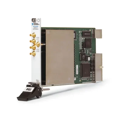
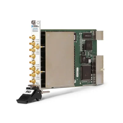
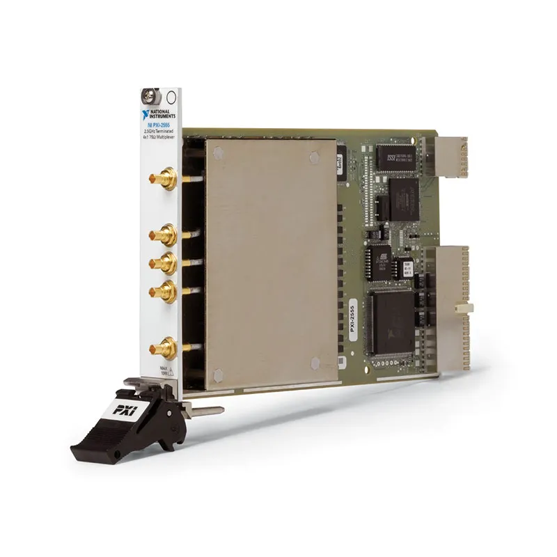
PXI-2555 2.5 GHz 75 Ω Terminated 4×1 RF Multiplexer
Земля PXI-2555 is a terminated 4×1 PXI RF multiplexer switch module designed for routing video, broadcast and other high-frequency 75 Ω signals. It connects one of four RF channels to a common port under software or hardware-triggered control.
Each unselected channel is connected to an internal 75 Ω termination. This maintains a defined impedance on inactive signal paths, reduces high-power reflections from open channels and helps protect sensitive RF sources used in video-related automated test systems.
The PXI-2555 supports signals from DC through 2.5 GHz with low insertion loss, controlled VSWR and high isolation. Onboard relay-count tracking helps engineers monitor switch usage, predict relay wear and schedule preventive maintenance.
Key Features of the PXI-2555
- Terminated 4×1 RF multiplexer topology
- Four selectable RF channels and one common port
- DC to 2.5 GHz signal-routing bandwidth
- 75 Ω nominal characteristic impedance
- Internal 75 Ω termination on each unselected channel
- 1.5 W termination rating at 25°C ambient
- 30 V maximum switching voltage
- 0.5 A maximum switching or carry current
- 10 W maximum channel-to-common RF power
- Less than 2 dB insertion loss through 2.5 GHz
- Greater than 43 dB typical isolation through 2.5 GHz
- Less than 30 ps typical channel-to-channel skew
- Electromechanical latching relays
- Onboard relay-count tracking
- PXI hardware trigger support
- Five gold-plated mini-75 Ω SMB connectors
- NI-SWITCH and NI Switch Executive compatibility
PXI-2555 Technical Specifications
| Product Model | PXI-2555 |
|---|---|
| Part Number | 778572-55 |
| Product Type | PXI RF multiplexer switch module |
| Topology | Terminated 4×1 multiplexer, SP4T |
| Number of Banks | 1 |
| Number of Channels | 4 channels plus 1 common port |
| Диапазон частот | DC to 2.5 GHz |
| Characteristic Impedance | 75 Ω nominal |
| Internal Termination | 75 Ω on each channel not connected to COM |
| Termination Power at 25°C | 1.5 W maximum, subject to ambient-temperature derating |
| Maximum Switching Voltage | 30 V |
| Maximum Switching Current | 0,5 А на канал |
| Maximum Carry Current | 0,5 А на канал |
| Maximum Channel-to-Common RF Power | 10 W |
| Initial DC Path Resistance | Less than 0.35 Ω typical |
| End-of-Life Path Resistance | 1.0 Ω or greater typical |
| Insertion Loss to 1 GHz | Less than 1.1 dB; less than 0.65 dB typical |
| Insertion Loss to 2 GHz | Less than 1.7 dB; less than 1.3 dB typical |
| Insertion Loss to 2.5 GHz | Less than 2.0 dB; less than 1.65 dB typical |
| Channel-to-Common VSWR to 1 GHz | Less than 1.3; less than 1.2 typical |
| Channel-to-Common VSWR to 2 GHz | Less than 1.65; less than 1.35 typical |
| Channel-to-Common VSWR to 2.5 GHz | Less than 1.75; less than 1.5 typical |
| Typical Isolation to 1 GHz | Greater than 49 dB |
| Typical Isolation to 2 GHz | Greater than 45 dB |
| Typical Isolation to 2.5 GHz | Greater than 43 dB |
| Channel-to-Channel Skew | Less than 30 ps typical |
| Propagation Delay | 1.2 ns typical |
| Rise Time | 90 ps typical, 10% to 90% |
| Тип реле | Electromechanical, latching |
| Maximum Relay Operate Time | 10.4 ms |
| Maximum Scan Rate | Approximately 45 channels/s |
| Mechanical Relay Life | 1 × 10⁶ cycles |
| Electrical Relay Life | 3 × 10⁵ cycles at 30 V and 10 mA resistive |
| Input Trigger Sources | PXI trigger lines 0 through 7 |
| Minimum Input Trigger Pulse Width | 150 ns with digital filtering enabled |
| Output Trigger Destinations | PXI trigger lines 0 through 7 |
| Output Trigger Pulse Width | Programmable from 1 µs to 62 µs |
| Front-Panel Connectors | 5 gold-plated mini-75 Ω SMB jacks |
| Поддержка программного обеспечения | NI-SWITCH and NI Switch Executive |
| Шинный интерфейс | PXI |
| Module Format | 3U, single-slot PXI/cPCI module |
| Dimensions | 21.6 × 2.0 × 13.0 cm |
| Weight | Approximately 218 g |
| Operating Temperature | 0°C to 55°C |
| Storage Temperature | -20°C to 70°C |
| Product Status | Discontinued by NI |
PXI-2555 Part Number and Accessories
| Item | Part Number | Описание |
|---|---|---|
| PXI-2555 | 778572-55 | 2.5 GHz, 75 Ω, terminated 4×1 PXI RF multiplexer |
| Mini-75 Ω SMB Cable | 197211-0R3 | 0.3 m mini-75 Ω SMB plug-to-plug coaxial cable |
| Mini-75 Ω SMB Cable | 197211-01 | 1 m mini-75 Ω SMB plug-to-plug coaxial cable |
| Type F to Mini-75 Ω SMB Cable | 197210-0R3 | 0.3 m Type F female to mini-75 Ω SMB plug coaxial cable |
The PXI-2555 uses mini-75 Ω SMB connectors rather than conventional 50 Ω SMB or SMA connections. Verify impedance, connector style, cable length and instrument interface before ordering accessories.
Terminated 4×1 Multiplexer Architecture
The PXI-2555 provides four selectable RF channels and one common connection. One channel can be connected to COM while the three unselected channels remain connected to their internal 75 Ω terminations.
The multiplexer can be used in either signal direction. A source connected to COM can be routed to one of four DUT inputs, or four device outputs can be selected individually for connection to one analyzer.
When the module is in its power-on state, all four channels are disconnected from COM and connected to their corresponding terminations.
Internal 75 Ω Channel Termination
Each input channel contains an internal 75 Ω termination. When a channel is not selected, the termination provides a defined load instead of allowing the port to remain open.
This helps prevent high-power reflections that can occur when a video or RF source sees an open circuit. It can also improve switching repeatability by maintaining consistent loading on disconnected sources.
The termination network is one of the principal differences between the PXI-2555 and the unterminated PXI-2554.
Termination Power Limit
Each internal termination is rated for a maximum of 1.5 W at an ambient temperature of 25°C. Termination power must be derated when ambient temperature rises above 25°C.
The terminations cannot withstand the module’s full 10 W channel-to-common rating. A signal that can safely pass through the selected relay path may damage an internal termination when its channel becomes unselected.
Before changing routes, calculate the power that will be absorbed by the newly terminated channel. Reduce or disable high-power RF sources when the termination rating could be exceeded.
75 Ω RF and Video Signal Paths
The PXI-2555 has a nominal 75 Ω characteristic impedance, matching the impedance used by many video, broadcast, cable television and coaxial distribution systems.
Use 75 Ω cables, sources and loads to maintain the published RF performance. Connecting 50 Ω equipment directly can introduce reflections, standing waves and amplitude error.
DC to 2.5 GHz Bandwidth
The PXI-2555 routes signals from DC through 2.5 GHz. This supports baseband and high-frequency video, broadcast RF, cable-device testing and other 75 Ω measurement applications.
Overall system bandwidth is affected by cables, adapters, fixtures and connected equipment. All parts of the route should support the intended frequency range.
Insertion Loss
Insertion loss is specified below 1.1 dB through 1 GHz, below 1.7 dB through 2 GHz and below 2 dB through 2.5 GHz.
The terminated design introduces slightly more loss than the related unterminated PXI-2554. The benefit is improved control of reflections on inactive channels.
For amplitude-sensitive measurements, characterize every complete route and apply frequency-dependent path-loss correction in the test software or measurement instrument.
Channel-to-Common VSWR
Channel-to-common VSWR is specified below 1.3 through 1 GHz, below 1.65 through 2 GHz and below 1.75 through 2.5 GHz.
Correctly rated 75 Ω cables and clean, secure connectors are necessary to preserve this performance. Mismatched adapters or instruments can dominate the total system VSWR.
Termination VSWR
The internal termination has its own frequency-dependent VSWR. Signals connected to unselected channels therefore see a practical 75 Ω termination rather than an ideal resistor across the entire frequency range.
When return loss is critical, characterize the terminated state at the required operating frequencies and signal levels.
Channel Isolation
Typical isolation is greater than 49 dB through 1 GHz, greater than 45 dB through 2 GHz and greater than 43 dB through 2.5 GHz.
Isolation helps prevent RF energy on inactive channels from coupling into the selected route. External cables and fixtures can reduce system-level isolation, especially when strong and weak signals are routed close together.
Propagation Delay and Channel Skew
Typical propagation delay is approximately 1.2 ns, while typical channel-to-channel skew is less than 30 ps. Typical 10% to 90% rise time is approximately 90 ps.
These characteristics support fast video and pulse routing. Match external cable lengths when timing alignment between channels is important.
30 V, 0.5 A and 10 W Ratings
The PXI-2555 supports switching voltages up to 30 V and switching or carry current up to 0.5 A per channel. The selected channel-to-common path can carry as much as 10 W.
These ratings apply simultaneously. The signal must remain within the voltage, current and power limits at the same time.
The internal termination has a separate, substantially lower power limit of 1.5 W at 25°C.
Avoid Switching Active RF Signals
NI recommends against changing routes while a high-power RF signal is active. During relay movement, the path is momentarily unterminated, which can reflect energy toward the source.
The signal can also be transferred from a 10 W-capable selected path to a termination rated for only 1.5 W. Reduce or disable the RF source before changing channels whenever practical.
Latching Electromechanical Relays
The PXI-2555 uses latching electromechanical relays. Latching relays maintain their commanded position without continuous coil power, reducing steady-state power consumption and heat.
Electromechanical switching provides low path resistance and good RF performance, but the contacts have a finite service life. Cold switching generally extends electrical relay life.
Relay Life and Relay-Count Tracking
Expected mechanical relay life is approximately 1 × 10⁶ operations. Expected electrical life is approximately 3 × 10⁵ operations at 30 V and 10 mA with a resistive load.
Onboard relay-count tracking records switching activity. Engineers can use these counts to identify heavily used channels and schedule preventive maintenance before a relay produces intermittent or high-resistance connections.
Hardware-Triggered Switching
The PXI-2555 accepts input triggers and exports output triggers through PXI trigger lines 0 through 7. Hardware triggering allows switching to be synchronized with digitizers, signal generators and RF analyzers.
The minimum input trigger pulse width is 150 ns with digital filtering enabled. Output trigger pulse width is programmable from 1 µs to 62 µs.
NI-SWITCH Software Support
The PXI-2555 is controlled using the NI-SWITCH instrument driver. NI-SWITCH provides functions for initialization, route connection, route disconnection, scanning, triggering and relay-count monitoring.
The driver supports LabVIEW, LabWindows/CVI and compatible text-based programming environments. Verify operating-system and driver compatibility when maintaining an older PXI controller.
NI Switch Executive Integration
NI Switch Executive allows developers to assign descriptive names to RF sources, analyzers, DUT ports and routes. This makes test programs easier to read than code based entirely on physical channel names.
Named routes can also coordinate the PXI-2555 with additional RF switches in larger automated test platforms.
Typical PXI-2555 Applications
- Terminated video RF signal routing
- Broadcast equipment testing
- Cable television device validation
- Video tuner testing
- Set-top box functional testing
- RF analyzer input selection
- Signal generator distribution
- Video modulator testing
- Automated production test equipment
- 75 Ω RF component characterization
- Receiver and tuner validation
- Laboratory video test automation
- Coaxial device testing
- High-frequency signal-path selection
Video Tuner Testing
The PXI-2555 can route a common video RF source to one of four tuner inputs while maintaining 75 Ω loads on the unselected channels.
Alternatively, several tuner outputs can be connected to the four channels and selected individually for measurement by one analyzer connected to COM.
Broadcast and Cable Equipment Testing
The 75 Ω architecture matches common broadcast and cable-system interfaces. Internal termination reduces the need to install separate external loads on every inactive source.
Verify that the power delivered by each source remains within the 1.5 W termination limit when the source is disconnected from COM.
Automated Production Testing
In production systems, the PXI-2555 replaces manual coaxial reconnection with repeatable software-controlled routing. Test software can select each DUT or test point automatically.
Relay-count tracking supports preventive maintenance and helps reduce intermittent failures caused by worn relay contacts.
PXI-2555 Troubleshooting
The PXI-2555 Is Not Detected in NI MAX
Confirm that the module is fully installed in a compatible PXI or hybrid slot. Check chassis power, controller communication and NI-SWITCH installation, then restart the system.
No Signal Reaches the Common Port
Verify that the correct channel is connected to COM. Check the source, mini-75 Ω SMB cable, destination instrument and NI-SWITCH route configuration.
The Signal Level Is Lower Than Expected
Account for switch insertion loss, cable attenuation and fixture loss. The PXI-2555 has slightly higher insertion loss than the unterminated PXI-2554.
The Signal Has Excessive Reflections
Confirm that all connected equipment and cables use 75 Ω impedance. Inspect the mini-SMB connectors and verify that the internal termination has not been damaged by excessive power.
A Termination Becomes Excessively Hot
Stop the test and disconnect the source. Verify that termination power remains below 1.5 W at 25°C and apply the required derating at higher ambient temperatures.
An RF Source Shuts Down During Switching
The source may be responding to momentary reflected power during relay operation. Disable or reduce its RF output before changing routes.
An Unselected Signal Appears at COM
Check external cable coupling and fixture isolation. Strong signals can bypass the intended switch path through poorly shielded or closely routed external wiring.
A Channel Has Excessive Path Resistance
Inspect the cables and connectors, then compare the route with another channel. Review relay-count information because increasing resistance can indicate contact wear.
The Triggered Scan Does Not Advance
Verify the PXI trigger line, direction, pulse width and scan-list configuration. Start the scan before the first hardware trigger is generated.
PXI-2555 Comparison with Similar 75 Ω RF Switches
| Модель | Primary Configuration | Best Suited For |
|---|---|---|
| PXI-2554 | 2.5 GHz, 75 Ω, unterminated 4×1 multiplexer | Applications using external termination |
| PXI-2555 | 2.5 GHz, 75 Ω, terminated 4×1 multiplexer | Protecting sources from reflections on inactive channels |
| PXI-2556 | 2.5 GHz, 75 Ω, dual 4×1 multiplexer | Parallel stimulus-and-response routing |
| PXI-2557 | 2.5 GHz, 75 Ω, 8×1 multiplexer | Higher-channel-count video RF selection |
| PXI-2558 | 2.5 GHz, 75 Ω, quad SPDT RF relay | Building custom changeover and multiplexer networks |
| PXI-2559 | 75 Ω RF relay architecture | Independent general-purpose video RF switching |
PXI-2555 vs PXI-2554
The PXI-2555 terminates every unselected channel with an internal 75 Ω load. The PXI-2554 leaves unselected channels unterminated.
The PXI-2555 is preferable when open-channel reflections could disturb or damage a source. The PXI-2554 offers lower insertion loss and is appropriate when termination is provided externally.
The internal PXI-2555 termination is limited to 1.5 W at 25°C, while its selected channel-to-common path supports up to 10 W.
PXI-2555 vs PXI-2556
The PXI-2555 provides one terminated 4×1 multiplexer. The PXI-2556 provides two independent 4×1 multiplexer banks but does not offer the same internally terminated topology.
Choose the PXI-2555 for controlled loading of inactive sources. Select the PXI-2556 when two signal paths must be routed simultaneously.
PXI-2555 vs PXI-2557
The PXI-2555 selects between four channels and provides internal termination. The PXI-2557 increases the channel count to an 8×1 architecture.
Choose the PXI-2555 when termination and source protection are the primary requirements. Select the PXI-2557 when one instrument must access a larger number of RF channels.
Recommended Related Products
- PXI-2554 Unterminated 4×1 RF Multiplexer
- PXI-2556 Dual 4×1 RF Multiplexer
- PXI-2557 8×1 RF Multiplexer
- PXI-2558 Quad SPDT RF Relay Module
- PXI-2559 75 Ω RF Relay Module
- View More NI PXI and PXI Express Modules
Selecting the Right 75 Ω RF Multiplexer
Choose the PXI-2555 when the application requires a 4×1 multiplexer, DC to 2.5 GHz frequency coverage and internal 75 Ω loading on every unselected channel.
Choose the PXI-2554 when external termination and lower insertion loss are preferred. Select the PXI-2556 for two parallel 4×1 paths or the PXI-2557 for an 8×1 configuration.
Why Choose the PXI-2555?
- Provides four-channel RF selection in one PXI slot
- Supports signals from DC to 2.5 GHz
- Maintains 75 Ω loading on inactive channels
- Helps reduce damaging open-channel reflections
- Provides low insertion loss and controlled VSWR
- Handles 30 V, 0.5 A and up to 10 W on the selected path
- Uses low-resistance latching relays
- Includes onboard relay-count tracking
- Supports hardware-triggered scanning
- Integrates with NI-SWITCH and NI Switch Executive
Frequently Asked Questions
What is the PXI-2555?
The PXI-2555 is a 2.5 GHz, 75 Ω PXI RF multiplexer with four selectable channels, one common port and internal termination on every unselected channel.
What is the PXI-2555 part number?
The standard NI part number is 778572-55.
What is the switch topology?
The PXI-2555 uses a terminated 4×1 multiplexer, also described as an SP4T configuration.
What is the frequency range?
The module routes signals from DC through 2.5 GHz.
What happens to an unselected channel?
An unselected channel is disconnected from COM and connected to its internal 75 Ω termination.
How much power can the internal termination handle?
The termination is rated for 1.5 W at 25°C ambient and must be derated at higher temperatures. It cannot withstand the full 10 W channel-to-common rating.
What is the maximum insertion loss?
Insertion loss is less than 1.1 dB through 1 GHz, less than 1.7 dB through 2 GHz and less than 2 dB through 2.5 GHz.
What type of connectors does it use?
The front panel provides five gold-plated mini-75 Ω SMB connectors.
What is the difference between PXI-2555 and PXI-2554?
The PXI-2555 terminates unselected channels internally. The PXI-2554 leaves the unselected channels unterminated and provides slightly lower insertion loss.
Does the PXI-2555 support relay-count tracking?
Yes. Onboard relay-count tracking helps monitor switching usage and schedule preventive maintenance.
Which software controls the module?
The PXI-2555 is controlled using NI-SWITCH and can be incorporated into named-route applications with NI Switch Executive.
Is the PXI-2555 still available from NI?
No. NI identifies the PXI-2555 as no longer available. Used, refurbished and new-surplus modules may remain available through specialized suppliers.
Request a Quote for the PXI-2555
Contact us for current availability, condition, testing options and project pricing for the PXI-2555 2.5 GHz 75 Ω Terminated 4×1 RF Multiplexer. We can also help identify compatible mini-75 Ω SMB cables, PXI chassis and related PXI-2554, PXI-2556 or PXI-2557 modules.















