




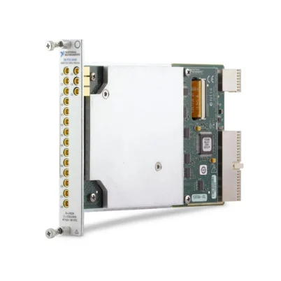
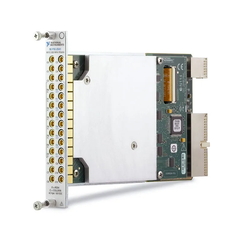
PXI-2541 300 MHz 8×12 PXI RF Matrix Switch Module
Земля PXI-2541 is an expandable 8×12 PXI RF matrix switch module designed for automated signal routing between RF generators, digitizers, oscilloscopes, function generators and other test instruments. Its nonblocking matrix architecture provides 96 independently controlled crosspoints and supports signal frequencies through 300 MHz.
The module uses 50 Ω nonlatching reed relays and 28 front-panel MCX connectors. Each channel supports switching voltages up to 60 VDC, current up to 0.5 A and RF or DC switching power up to 10 W, subject to frequency and simultaneous-channel derating.
For applications requiring more than 12 columns, Row Out connections allow multiple PXI-2541 modules to be cascaded into 8×24, 8×36 and larger switching matrices.
Key Features of the PXI-2541
- 8×12 nonblocking RF matrix topology
- 96 independently controlled matrix crosspoints
- 300 MHz RF bandwidth
- 50 Ω nominal characteristic impedance
- Expandable column architecture
- Supports 8×24, 8×36 and larger matrices
- 60 VDC maximum switching voltage
- 0.5 A maximum switching or carry current per channel
- 10 W maximum DC switching power per channel
- 10 W maximum RF power per channel in a 50 Ω system
- Less than 3 dB specified matrix-path insertion loss at 300 MHz
- Greater than 75 dB typical open-channel isolation
- Less than -35 dB typical crosstalk
- Nonlatching rhodium reed relays
- 0.25 ms maximum relay operate and release time
- 28 front-panel MCX connectors
- PXI hardware trigger support
- Onboard relay-count tracking
- NI-SWITCH software support
- NI Switch Executive compatibility
- Single-slot 3U PXI module
PXI-2541 Technical Specifications
| Product Model | PXI-2541 |
|---|---|
| Part Number | 778572-41 |
| Product Type | PXI RF matrix switch module |
| Topology | 8×12 matrix |
| Matrix Crosspoints | 96 |
| Design | Nonblocking, expandable RF matrix |
| Пропускная способность | 300 MHz |
| Characteristic Impedance | 50 Ω nominal |
| Maximum Switching Voltage | 60 VDC or 42.4 Vpk |
| Maximum Switching or Carry Current | 0,5 А на канал |
| Maximum DC Switching Power | 10 Вт на канал |
| Maximum RF Power | 10 W per channel in a 50 Ω system |
| Maximum-Power Simultaneous Channels | 3 through 300 MHz, subject to derating requirements |
| Initial DC Path Resistance | Less than 2.1 Ω typical |
| End-of-Life Path Resistance | 3.1 Ω or greater typical |
| Row In-to-Column Insertion Loss | Less than 3 dB through 300 MHz; less than 2.1 dB typical |
| Row In-to-Row Out Insertion Loss | Less than 1 dB through 300 MHz; less than 0.5 dB typical |
| Row In-to-Column VSWR | Less than 2.2 through 300 MHz; less than 1.6 typical |
| Row In-to-Row Out VSWR | Less than 1.8 through 300 MHz; less than 1.5 typical |
| Open-Channel Isolation | Greater than 75 dB typical, Row In to Column, through 300 MHz |
| Crosstalk | Less than -35 dB typical through 300 MHz |
| Propagation Delay | Less than 6 ns typical, Row In to Column |
| Channel-to-Channel Skew | Less than 2 ns typical, Row In to Column |
| Тип реле | Nonlatching reed relay |
| Relay Contact Material | Rhodium |
| Maximum Relay Operate Time | 0.25 ms |
| Maximum Relay Release Time | 0.25 ms |
| Typical Mechanical Relay Life | 10 million cycles |
| Simultaneous Relay Drive Limit | 40 relays |
| Input Trigger Sources | PXI trigger lines 0 through 7 |
| Minimum Trigger Pulse Width | 150 ns |
| Output Trigger Destinations | PXI trigger lines 0 through 7 |
| Front-Panel Connectors | 28 MCX jacks |
| Поддержка программного обеспечения | NI-SWITCH and NI Switch Executive |
| Operating Temperature | 0°C to 55°C |
| Dimensions | 21.6 cm × 2.0 cm × 13.0 cm |
| Weight | 410 g |
| Module Format | 3U, single-slot PXI module |
| Life-Cycle Status | Discontinued |
| PXI Express Alternative | PXIe-2541, part number 780587-41 |
PXI-2541 Part Number and Compatible Cables
| Item | Part Number | Описание |
|---|---|---|
| PXI-2541 | 778572-41 | 300 MHz, 8×12, 50 Ω PXI RF matrix switch module |
| PXIe-2541 | 780587-41 | PXI Express version of the expandable 8×12 RF matrix |
| MCX-to-MCX Cable | 188374-01 | 1 m cable for MCX signal routing and matrix connections |
| MCX-to-MCX Cable | 188374-0R3 | 30 cm cable for short MCX connections |
| MCX-to-MCX Expansion Cable | 188374-0R15 | 15 cm cable recommended for cascading adjacent matrix modules |
| MCX-to-BNC Cable | 188375-01 | 1 m cable for connecting the matrix to BNC instruments |
| MCX-to-BNC Cable | 188375-0R3 | 30 cm MCX-to-BNC cable |
| MCX-to-SMB Cable | 188376-01 | 1 m cable for instruments using SMB connectors |
| MCX-to-SMB Cable | 188376-0R3 | 30 cm MCX-to-SMB cable |
| MCX-to-SMA Cable | 188377-01 | 1 m cable for connecting SMA RF instruments and fixtures |
The PXI-2541 uses 28 MCX front-panel connectors for its row, column and expansion connections. Confirm the number, length and connector combination of all required cables before ordering.
8×12 RF Matrix Architecture
The PXI-2541 provides eight rows and 12 columns, creating 96 independently controlled crosspoints. Closing a crosspoint connects the selected row to the selected column.
The matrix topology allows RF sources and measurement instruments to be connected to multiple devices or fixture points under software control. This reduces manual cable changes and allows a single instrument to serve many test paths.
Nonblocking Signal Routing
The nonblocking design permits multiple row-to-column connections to be active simultaneously, subject to electrical loading, signal interaction and relay-drive limits.
Isolation relays disconnect unused sections of the matrix to help maintain RF isolation and reduce the loading produced by inactive signal paths.
Before closing several crosspoints, verify that the planned routes do not connect incompatible sources together or create an unintended signal conflict.
Expandable Column Architecture
Each row provides separate Row In and Row Out connections. Row Out connectors from one PXI-2541 can be connected to the corresponding Row In connectors of another module to expand the number of columns.
Two modules create an 8×24 matrix, three modules create an 8×36 matrix and additional modules can be cascaded for larger routing systems. The 15 cm MCX-to-MCX cable, part number 188374-0R15, is designed for short connections between adjacent modules.
Every cascaded module and expansion cable adds insertion loss and propagation delay. Evaluate the complete expanded path against the required signal amplitude, bandwidth and timing performance.
300 MHz RF Bandwidth
The PXI-2541 routes DC and RF signals through 300 MHz in a nominal 50 Ω environment. This bandwidth supports function-generator signals, intermediate-frequency paths, lower-frequency RF signals and many automated instrumentation connections.
System bandwidth also depends on external cables, adapters, fixtures and connected instruments. Use properly terminated 50 Ω components and keep cable lengths as short as practical.
50 Ω Signal Paths
The module is designed for a nominal 50 Ω system. Correct impedance matching reduces reflections, ringing and amplitude errors, especially as the routed signal approaches the upper frequency range.
When a high-impedance instrument is connected to the matrix, the resulting signal amplitude may differ from the level expected with a 50 Ω termination. Configure the source and receiving instrument for the actual load.
RF Insertion Loss
The specified Row In-to-Column insertion loss is less than 3 dB through 300 MHz, with typical performance below 2.1 dB. The Row In-to-Row Out expansion path has less than 1 dB specified insertion loss and less than 0.5 dB typical insertion loss.
Insertion loss increases with frequency and matrix expansion. Calibrate the complete signal path when accurate RF power or amplitude measurements are required.
Open-Channel Isolation
Typical open-channel isolation from Row In to a disconnected column is greater than 75 dB through 300 MHz. High isolation helps prevent a strong signal on one route from leaking into an inactive measurement path.
Actual system isolation can be limited by cable coupling, fixture layout, grounding and external switch hardware. Separate sensitive low-level paths from high-power signal cables whenever possible.
Crosstalk Performance
Typical crosstalk is less than -35 dB through 300 MHz. Crosstalk describes unwanted signal coupling between simultaneously active or adjacent matrix paths.
When routing signals with a large difference in amplitude, verify that coupled energy remains below the measurement or device-under-test tolerance.
Signal Propagation and Skew
Typical Row In-to-Column propagation delay is less than 6 ns, with channel-to-channel skew below 2 ns. These characteristics are relevant when routing pulses, clocks and synchronized signals.
Cables and expansion modules add additional delay and skew. Systems requiring precise timing alignment should characterize the complete installed signal paths.
60 V and 0.5 A Switching Capability
The PXI-2541 supports switching voltages up to 60 VDC or 42.4 Vpk and switching or carry current up to 0.5 A per channel. Maximum switching power must not exceed 10 W per channel.
The voltage, current and power limits apply simultaneously. A route operating at the maximum voltage cannot necessarily switch the maximum current because doing so would exceed the 10 W power limit.
10 W RF Power Handling
In a correctly terminated 50 Ω system, the module supports RF power up to 10 W per channel under specified conditions. Up to three channels can operate simultaneously at the maximum RF power through 300 MHz, subject to the official frequency and channel-count derating curves.
NI recommends avoiding the switching of active RF signals. During relay movement, the route is momentarily unterminated, which can reflect energy toward the RF source. Disable or reduce the source output before changing routes whenever practical.
Nonlatching Reed Relays
The PXI-2541 uses nonlatching reed relays with rhodium contacts. Reed relays provide good RF isolation, fast switching and a defined default state when power is removed.
Maximum operate and release times are 0.25 ms. Additional settling time may be necessary when the connected instrument or device under test requires signal stabilization after switching.
Relay Life and Maintenance
Typical mechanical relay life is 10 million operations. Electrical life depends on the switched voltage, current, power, load type and frequency of operation.
Capacitive loads can create high inrush current, while inductive loads can produce flyback voltage when opened. External protection can reduce relay stress and extend operating life.
NI-SWITCH relay-count tracking can help identify heavily used crosspoints and support preventive-maintenance planning.
PXI Hardware Triggering
The PXI-2541 can accept input triggers from PXI trigger lines 0 through 7. The minimum specified input pulse width is 150 ns when digital filtering is enabled.
Output triggers can also be routed to PXI trigger lines 0 through 7. Hardware triggering allows switching operations to be coordinated with generators, digitizers and automated measurement sequences.
Typical PXI-2541 Applications
- Automated RF signal routing
- Production functional testing
- Digitizer input selection
- Function-generator output distribution
- RF source and analyzer routing
- Intermediate-frequency signal switching
- Multichannel device testing
- Полупроводниковые системы тестирования
- Communications-device validation
- Research and laboratory automation
- Test-fixture signal selection
- Expandable RF matrix systems
Automated Instrument Routing
The PXI-2541 can connect multiple instruments to multiple device-under-test points without manual recabling. Software can select the required source and measurement routes at each stage of a test sequence.
For example, a function generator can be routed to several DUT inputs while an oscilloscope or digitizer measures different output nodes. Route validation should prevent incompatible sources from being connected together.
Production Test Systems
In production testing, the matrix allows the same set of instruments to test many channels or fixture positions. Automated routing improves repeatability and reduces connector wear caused by manual cable changes.
Named routes can be defined for different product variants, allowing one test station to support several fixtures or configurations.
RF and IF Signal Distribution
The 300 MHz bandwidth makes the PXI-2541 suitable for distributing RF and intermediate-frequency signals among analyzers, generators and devices under test.
The matrix is bidirectional from an electrical routing perspective, but route names should clearly identify intended signal flow to simplify system maintenance and avoid source conflicts.
NI-SWITCH Software Support
The PXI-2541 is controlled with the NI-SWITCH instrument driver. NI-SWITCH provides functions for initializing the module, connecting and disconnecting routes, creating scan lists, configuring triggers and reading relay-count information.
The driver supports LabVIEW, LabWindows/CVI and compatible text-based programming environments. Verify driver compatibility when installing the discontinued PXI-2541 in a newer operating system.
NI Switch Executive Integration
NI Switch Executive allows engineers to define virtual devices, named signals, routes and route groups. Applications can then request a meaningful route instead of controlling individual matrix crosspoints directly.
Named routing is especially useful when several PXI-2541 modules are cascaded into a larger matrix. It reduces application complexity and helps prevent conflicting connections.
PXI-2541 Troubleshooting
The PXI-2541 is not detected in NI MAX
Confirm that the module is fully installed in a compatible PXI slot. Check chassis power, controller communication and NI-SWITCH installation, then refresh the hardware list in NI Measurement & Automation Explorer.
A selected route does not pass the signal
Verify the row and column names used by the application. Check the front-panel MCX cables, fixture wiring and route state. Use a low-frequency continuity test when appropriate to isolate the failed section.
The routed RF signal is weaker than expected
Account for matrix insertion loss, cable loss, adapter loss and expansion-module loss. Confirm that every instrument and cable uses the intended 50 Ω impedance.
The signal contains reflections or ringing
Inspect the route for impedance mismatches, unterminated branches and damaged RF cables. Verify that the source, matrix, cables and receiving instrument all use compatible 50 Ω termination.
There is excessive signal leakage
Check whether another route is unintentionally closed. Inspect cable spacing, fixture shielding and grounding because external coupling can reduce system isolation below the module specification.
An expanded matrix has too much insertion loss
Every expansion cable and module adds loss. Reduce the number of cascaded sections, shorten the cables or add a suitable amplifier when the complete path no longer meets the signal-level requirement.
A relay does not switch reliably
Check the relay-count history and measure route resistance. A significant increase in resistance may indicate relay wear. Verify that the channel has not been exposed to excessive power, capacitive inrush or inductive flyback.
The module reports a route conflict
Review the active connections in NI Switch Executive or the application. Make sure two sources are not being connected to the same matrix node and that route exclusions are configured correctly.
The RF source reports a protection fault
A relay can momentarily leave an active source unterminated while switching. Disable the RF output before changing the route or use external protection appropriate for the source.
Hardware-triggered switching does not occur
Verify the selected PXI trigger line, trigger direction and pulse width. Confirm that the switch is armed before the trigger arrives and that another module is not driving the same trigger line incorrectly.
PXI-2541 Comparison with Related RF Matrix Modules
| Модель | Primary Configuration | Best Suited For |
|---|---|---|
| PXI-2540 | 350 MHz, 8×9, 50 Ω RF matrix | Higher bandwidth with fewer columns |
| PXI-2541 | 300 MHz, 8×12, expandable RF matrix | Legacy PXI systems requiring greater column density |
| PXIe-2540 | 350 MHz, 8×9 PXI Express RF matrix | Modern PXI Express systems with higher bandwidth |
| PXIe-2541 | 300 MHz, 8×12 expandable PXI Express matrix | PXI Express replacement for PXI-2541 applications |
| PXI-2593 | 500 MHz, 4×16 RF matrix | Applications requiring more columns and higher bandwidth |
PXI-2541 vs PXI-2540
The PXI-2541 provides an 8×12 matrix with 300 MHz bandwidth, while the PXI-2540 provides an 8×9 matrix with bandwidth through 350 MHz.
Choose the PXI-2541 when additional columns and expandable 8×24 or 8×36 configurations are more important. Select the PXI-2540 when the smaller 8×9 topology is sufficient and the additional bandwidth is useful.
PXI-2541 vs PXIe-2541
The PXI-2541 and PXIe-2541 offer the same basic 8×12, 300 MHz, 50 Ω expandable matrix architecture. The primary difference is the chassis bus interface.
The PXI-2541 is part number 778572-41 and is intended for legacy PXI systems. The PXIe-2541 is part number 780587-41 and is the preferred version for compatible PXI Express systems.
PXI-2541 vs PXI-2593
The PXI-2541 provides eight rows and 12 columns with 300 MHz bandwidth. The PXI-2593 provides a 4×16 topology and higher bandwidth through 500 MHz.
Select the PXI-2541 when eight independent row connections are required. Choose the PXI-2593 when additional columns and higher-frequency routing are more important than row count.
Recommended Related Products
- PXI-2540 350 MHz 8×9 RF Matrix Switch
- PXIe-2540 350 MHz 8×9 RF Matrix Switch
- PXIe-2541 300 MHz 8×12 RF Matrix Switch
- PXI-2593 500 MHz 4×16 RF Matrix Switch
- PXI-2542 Quad 2×1 RF Multiplexer
- PXI-2543 Dual 4×1 RF Multiplexer
- PXI-2544 8×1 RF Multiplexer
- View More NI PXI and PXI Express Modules
Selecting the Right RF Matrix Switch
Choose the PXI-2541 when an existing PXI system requires eight rows, 12 columns, 300 MHz bandwidth and the ability to create larger matrices through column expansion.
Select the PXI-2540 when an 8×9 topology is sufficient and slightly higher bandwidth is required. For newer PXI Express systems, use the PXIe-2541. Consider the PXI-2593 when a 4×16 configuration and 500 MHz bandwidth better match the signal-routing requirement.
Why Choose the PXI-2541?
- Provides 96 independently controlled RF matrix crosspoints
- Routes DC and RF signals through 300 MHz
- Supports nonblocking row-to-column connections
- Expands into 8×24, 8×36 and larger matrices
- Maintains 50 Ω signal-path impedance
- Offers high open-channel isolation
- Uses fast nonlatching reed relays
- Supports PXI triggering and relay-count tracking
- Integrates with NI-SWITCH and NI Switch Executive
- Fits into a single 3U PXI slot
Frequently Asked Questions
What is the PXI-2541?
The PXI-2541 is a 300 MHz, 8×12, 50 Ω PXI RF matrix switch used to route signals between multiple instruments and devices under test.
How many crosspoints does the PXI-2541 provide?
The 8×12 matrix contains 96 independently controlled row-to-column crosspoints.
What is the PXI-2541 bandwidth?
The specified RF bandwidth is 300 MHz.
Can the PXI-2541 matrix be expanded?
Yes. Row Out connectors can be connected to another module’s Row In connectors to create 8×24, 8×36 and larger matrices.
What is the maximum switching voltage?
The maximum switching voltage is 60 VDC or 42.4 Vpk.
What is the maximum switching current?
The maximum switching or carry current is 0.5 A per channel.
What is the maximum RF power?
The maximum RF power is 10 W per channel in a 50 Ω system, subject to frequency and simultaneous-channel derating.
Which connector does the PXI-2541 use?
The module has 28 front-panel MCX jacks for row, column and expansion connections.
Which driver controls the PXI-2541?
The module is controlled through NI-SWITCH and can be configured with named routes using NI Switch Executive.
What is the PXI-2541 part number?
The standard NI part number is 778572-41.
Is the PXI-2541 still available from NI?
No. NI identifies the PXI-2541 as no longer available. Used, refurbished or surplus modules may remain available.
What is the PXI Express alternative?
The PXIe-2541, part number 780587-41, provides the corresponding 300 MHz, 8×12 expandable RF matrix for compatible PXI Express systems.
What should be checked before purchasing a used PXI-2541?
Verify the exact part number, relay counts, crosspoint operation, RF insertion loss, path resistance, MCX connector condition and included expansion cables. The module should be tested across multiple rows and columns rather than through only one route.
Request a Quote for the PXI-2541
Contact us for current availability, test condition and project pricing for the PXI-2541 300 MHz 8×12 PXI RF Matrix Switch Module. We can also help identify compatible MCX cables, PXI chassis, expansion modules and related RF switching products.















