






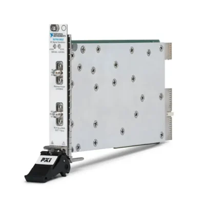
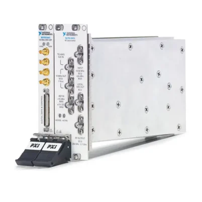
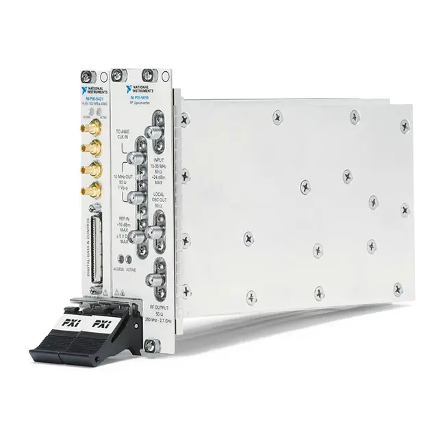
PXI-5670 2.7 GHz PXI Vector Signal Generator
Земля PXI-5670 is a modular PXI vector signal generator designed for RF communications, semiconductor, aerospace, defense and wireless-device testing. It generates continuous-wave and vector-modulated RF signals over a frequency range from 250 kHz to 2.7 GHz.
The PXI-5670 combines an NI PXI-5421 arbitrary waveform generator with an NI PXI-5610 RF upconverter. The PXI-5421 creates a modulated intermediate-frequency waveform, while the PXI-5610 converts the signal to the selected RF output frequency.
The system provides 20 MHz of instantaneous modulation bandwidth and supports standard and custom formats such as AM, FM, PM, ASK, FSK, PSK, MSK and QAM. Software-defined waveform generation makes it suitable for product development, validation and automated production testing.
Key Features of the PXI-5670
- 250 kHz to 2.7 GHz RF frequency range
- 20 MHz instantaneous modulation bandwidth
- Up to +10 dBm RF output power
- 16-bit arbitrary waveform generation
- 100 MS/s base sample rate
- Up to 400 MS/s interpolated waveform rate
- AM, FM and PM analog modulation
- ASK, FSK, PSK, MSK and QAM digital modulation
- Support for custom user-defined modulation
- CW and vector-modulated signal generation
- Approximately ±0.7 dB amplitude accuracy
- Typical -95 dBc/Hz phase noise at a 10 kHz offset
- Typical -120 dBm/Hz output noise density at 0 dBm
- Phase-continuous waveform generation
- Waveform scripting and sequencing
- 8 MB, 32 MB, 256 MB and 512 MB memory options
- PXI triggering and reference-clock synchronization
- NI-RFSG and NI-FGEN software support
PXI-5670 Technical Specifications
| Product Model | PXI-5670 |
|---|---|
| Product Type | PXI vector signal generator |
| Диапазон частот | 250 kHz to 2.7 GHz |
| Instantaneous Modulation Bandwidth | 20 MHz |
| Maximum RF Output Power | +10 dBm |
| Amplitude Accuracy | Approximately ±0.7 dB |
| Typical Output Noise Density at 0 dBm | -120 dBm/Hz |
| Typical Phase Noise | -95 dBc/Hz at 10 kHz offset |
| Typical CW Tuning Time | 35 ms |
| Typical Arbitrary-Waveform Tuning Time | 4.2 s |
| Vector Modulation Bandwidth Flatness | ±0.5 dB typical with equalization enabled |
| Group Delay Deviation | ±20 ns typical within the vector modulation bandwidth |
| Analog Modulation | AM, FM and PM |
| Digital Modulation | ASK, FSK, PSK, MSK, QAM and custom formats |
| AWG Resolution | 16 bits |
| AWG Base Sample Rate | 100 MS/s |
| AWG Interpolated Rate | Up to 400 MS/s |
| Onboard Memory Options | 8 MB, 32 MB, 256 MB or 512 MB |
| RF Upconverter Module | PXI-5610 |
| Arbitrary Waveform Generator | PXI-5421 |
| RF Output Connector | SMA |
| Reference and Intermodule Connections | SMA and SMB coaxial connectors |
| Trigger Source Module | PXI-5421 |
| Total Slot Requirement | Three PXI slots |
| PXI-5610 Format | 3U, two-slot PXI module |
| PXI-5421 Format | 3U, one-slot PXI module |
| Combined Weight | 1,510 g nominal |
| Шинный интерфейс | Conventional PXI |
| Поддержка программного обеспечения | NI-RFSG, NI-FGEN, LabVIEW and compatible text-based environments |
| Lifecycle Status | No longer available from NI and under limited support |
| NI Recommended Replacement | PXI-5671 configuration with 512 MB, part number 779079-04 |
PXI-5670 Part Numbers and Memory Options
| Part Number | Onboard Waveform Memory | Описание |
|---|---|---|
| 778768-01 | 8 MB | PXI-5670 vector signal generator with PXI-5421 and PXI-5610 modules |
| 778768-02 | 32 MB | PXI-5670 with expanded waveform memory |
| 778768-03 | 256 MB | PXI-5670 for longer waveform records and sequences |
| 778768-04 | 512 MB | PXI-5670 with the maximum available PXI-5421 memory configuration |
The memory option is associated with the PXI-5421 arbitrary waveform generator included in the kit. The PXI-5610 upconverter, operating frequency range and primary RF specifications remain the same across the four PXI-5670 part numbers.
PXI-5670 System Components
| Component | Component Part Number | Function |
|---|---|---|
| PXI-5610 | 778737-01 | 250 kHz to 2.7 GHz RF upconverter |
| PXI-5421 | Memory dependent | 16-bit, 100 MS/s arbitrary waveform and IF signal generator |
| SMA-to-SMB Interconnect Cables | 190846 series | Connects the AWG waveform and reference clock to the RF upconverter |
| Cable Wrenches | 746016-01 | Supports proper handling of the semi-flexible coaxial cable connectors |
The PXI-5670 is a multi-module instrument. There is no single physical module labeled PXI-5670; the model name refers to the calibrated system formed by the PXI-5610 and PXI-5421 with their required interconnection cables.
PXI-5421 Arbitrary Waveform Generator
The PXI-5421 creates the modulated intermediate-frequency waveform used by the PXI-5670. It provides 16-bit resolution and a 100 MS/s base sample rate with interpolation up to 400 MS/s.
The AWG stores I/Q or real waveform samples in onboard memory and can generate them continuously, as a triggered burst or through a scripted sequence. The amount of available memory depends on the selected PXI-5670 part number.
The PXI-5421 also manages PXI trigger sharing for the complete PXI-5670 system. When configuring backplane trigger routes, the AWG module name should be selected as the relevant hardware endpoint.
PXI-5610 RF Upconverter
The PXI-5610 converts the waveform generated by the PXI-5421 to the selected RF carrier frequency. Its superheterodyne architecture provides RF generation from 250 kHz to 2.7 GHz.
The upconverter contains the RF frequency-conversion, local-oscillator, filtering, attenuation and output-level-control circuitry. It also supplies a reference signal to the PXI-5421 through the required front-panel cable.
Intermodule Cable Connections
The PXI-5421 waveform output connects to the PXI-5610 input through a semi-flexible SMA-to-SMB coaxial cable. A second cable connects the upconverter’s 10 MHz reference output to the AWG clock input.
Both cables are necessary for normal operation. Incorrectly connected, loose or damaged cables can cause initialization errors, unlocked reference clocks, reduced output level or poor modulation quality.
Use the specified cable tools and avoid repeatedly bending semi-flexible coaxial cables. Confirm the exact cable routing in the NI getting-started guide before applying power.
250 kHz to 2.7 GHz Frequency Coverage
The PXI-5670 covers RF frequencies from 250 kHz to 2.7 GHz. This range supports low-frequency communications research and many common wireless, broadcast, RFID, navigation and industrial radio bands.
Applications above 2.7 GHz require another vector signal generator. The PXIe-5673E extends coverage to 6.6 GHz, while modern PXI vector signal transceivers provide higher frequencies and wider instantaneous bandwidth.
20 MHz Instantaneous Bandwidth
The generator supports as much as 20 MHz of instantaneous vector modulation bandwidth. It can therefore generate complex signals whose occupied bandwidth fits within this range without retuning the RF carrier.
The usable bandwidth depends on the waveform sample rate, digital filtering, modulation format and equalization configuration. Wideband signals should be verified with a suitable vector signal analyzer.
RF Output Power
The PXI-5670 provides RF output power up to +10 dBm. Programmable attenuation and digital waveform scaling allow lower output levels to be configured for receiver and component testing.
The power delivered to the DUT depends on cable loss, external attenuation, connectors and fixture insertion loss. For accurate DUT input power, characterize the entire signal path or measure the level at the fixture reference plane.
Amplitude Accuracy
Specified amplitude accuracy is approximately ±0.7 dB under applicable operating and calibration conditions. Temperature correction and calibration data help maintain stable output across the supported frequency range.
Allow the hardware to warm up and verify the calibration status before precision measurements. Additional uncertainty must be included for cables, switches, attenuators and fixture connections.
Output Noise Performance
At a 0 dBm output setting, typical output noise density is approximately -120 dBm/Hz. The noise floor changes with the configured output power and internal attenuation.
For receiver-sensitivity testing, use the appropriate power range and external filtering when necessary. Residual noise and spurious signals should be compared with the DUT’s required test limits.
Phase Noise Performance
The PXI-5670 provides typical phase noise of approximately -95 dBc/Hz at a 10 kHz offset under the specified conditions. Phase-noise performance affects error vector magnitude, adjacent-channel behavior and receiver testing.
The actual result depends on carrier frequency, offset frequency, reference-clock quality and chassis environment. Use an appropriate external reference when the system must share frequency accuracy with other RF equipment.
Analog Modulation
The PXI-5670 supports amplitude, frequency and phase modulation. Engineers can configure modulation parameters programmatically and combine them with automated RF frequency and power sweeps.
Analog modulation is useful for receiver testing, communications research, legacy radio validation and sensor-system development.
Digital Modulation
Supported digital modulation formats include ASK, FSK, PSK, MSK and QAM. Custom waveform generation allows users to implement additional formats that fit within the instrument’s bandwidth and memory capabilities.
Modulated waveform creation may use NI modulation software, LabVIEW or externally generated I/Q data. The waveform can then be downloaded to the PXI-5421 and upconverted to the selected RF carrier.
QAM Signal Generation
Quadrature amplitude modulation varies both the amplitude and phase of the RF carrier. The PXI-5670 can generate QAM signals for transmitter, receiver and component validation.
Modulation quality depends on waveform scaling, filter configuration, symbol rate, carrier frequency and system calibration. Avoid clipping the I/Q samples because clipping can degrade error vector magnitude and spectral regrowth.
PSK and MSK Generation
Phase-shift keying and minimum-shift keying signals can be generated for digital communications testing. Configurable pulse shaping allows the occupied bandwidth and transition behavior to match the intended system.
The generator can be paired with a PXI vector signal analyzer to measure error vector magnitude, constellation behavior, occupied bandwidth and adjacent-channel power.
Custom Modulation Formats
The arbitrary waveform architecture allows engineers to create custom modulation formats instead of being limited to predefined personalities. This is useful for proprietary radio protocols, research waveforms and emerging wireless systems.
Custom I/Q samples must be created with the correct sample rate, scaling and filtering. Verify that the resulting signal remains within the 20 MHz instantaneous bandwidth.
Continuous-Wave Generation
The PXI-5670 can operate as a continuous-wave RF source for gain, compression, frequency-response and sensitivity measurements. Typical CW frequency tuning time is approximately 35 ms.
CW mode generally tunes faster than arbitrary-waveform mode because a new waveform does not need to be configured and downloaded for every frequency setting.
Waveform Scripting and Sequencing
The PXI-5421 supports waveform scripting and sequencing. Stored waveform records can be repeated, triggered or arranged into a defined test sequence without transferring every sample again.
Scripts can create packet bursts, alternating modulation states, preambles, gaps and other time-domain structures. Larger memory configurations support longer sequences and additional stored signals.
Attenuator Hold
Attenuator-hold mode allows output power to be adjusted without repeatedly switching the PXI-5610’s mechanical attenuation setting. The attenuator remains set for the highest required level, while lower levels are produced by digitally scaling the waveform.
This feature can provide smoother power sweeps and reduce discontinuities associated with attenuator changes. Digital scaling reduces the number of DAC codes used and may therefore decrease signal-to-noise ratio at lower power settings.
External Reference Clock
The PXI-5610 includes reference input and output connections for synchronizing the RF generator with other test equipment. A shared 10 MHz reference can improve frequency coherence across signal generators, analyzers and other instruments.
The intermodule reference connection between the PXI-5610 and PXI-5421 must remain installed even when the system uses an external reference.
PXI Triggering
The PXI-5670 can use PXI backplane trigger resources to synchronize RF generation with digitizers, switches and other instruments. The PXI-5421 is the submodule responsible for importing and exporting PXI trigger signals for the combined generator.
Hardware triggering allows waveform generation to begin at a more repeatable point than software-only control. Verify trigger polarity, source, destination and delay during system integration.
RF Receiver Testing
The PXI-5670 can generate controlled RF signals for receiver sensitivity, selectivity and demodulation testing. Frequency, power and modulation can be changed automatically across a test sequence.
When performing very-low-level receiver tests, account for residual generator noise and leakage. External attenuation or filtering may improve the signal environment at the DUT.
RFID Testing
The frequency range and custom modulation capabilities support the development and validation of radio-frequency identification systems. Engineers can generate reader or tag-related waveforms within the instrument’s bandwidth and power limits.
Custom waveform sequencing can reproduce bursts, commands and response timing for supported RFID protocols.
Wireless Sensor Network Testing
The PXI-5670 can generate packet-based and custom RF signals used by wireless sensor networks. Test software can vary frequency, modulation, output power and packet content to evaluate receiver behavior.
Automated testing can characterize sensitivity, packet-error rate, adjacent-channel performance and response to impaired signals.
Semiconductor RF Testing
The generator can provide CW and modulated stimuli for amplifiers, mixers, filters, modulators and receiver ICs. It can be combined with PXI digitizers, vector signal analyzers, power meters and switching modules in a semiconductor test system.
External amplifiers or attenuators may be required when the DUT input level falls outside the generator’s direct operating range.
Aerospace and Defense Applications
Custom waveform generation, hardware triggering and PXI integration make the PXI-5670 suitable for legacy aerospace and defense RF validation systems. It can generate defined communication, navigation and test waveforms within its 2.7 GHz range.
The complete system must satisfy the application’s calibration, environmental, security and signal-integrity requirements.
Software-Defined Radio Research
Researchers can create baseband I/Q waveforms in software and use the PXI-5670 to translate them to RF. This supports experimentation with new modulation formats, coding methods and receiver algorithms.
Waveform design and analysis can be combined in LabVIEW or compatible programming environments to create a complete transmit-and-receive research platform.
NI-RFSG Software Support
The PXI-5670 operates as one logical RF signal generator through the NI-RFSG instrument driver. NI-RFSG coordinates frequency, power, waveform download, triggering and communication between the PXI-5421 and PXI-5610.
Applications should initialize the PXI-5670 as the combined RFSG device rather than attempting to control each component independently during normal vector signal generation.
NI-FGEN Integration
The PXI-5421 can also be accessed through NI-FGEN for supported standalone arbitrary waveform applications. This can be useful when the module is no longer required as part of the complete RF generator.
Direct component-level control requires a clear understanding of the intermodule signal path and should not be mixed with active NI-RFSG control of the same system.
Typical PXI-5670 Applications
- RF receiver sensitivity testing
- Digital communications validation
- AM, FM and PM signal generation
- ASK, FSK, PSK, MSK and QAM testing
- RFID system development
- Wireless sensor network testing
- Software-defined radio research
- Semiconductor RF component testing
- Aerospace and defense communications testing
- Consumer wireless-device validation
- Automated production testing
- Custom RF waveform generation
PXI-5670 Troubleshooting
The PXI-5670 Is Not Detected
Confirm that both the PXI-5610 and PXI-5421 are fully installed in compatible PXI slots. Check chassis power, controller communication and NI-RFSG installation, then inspect both modules in NI Measurement & Automation Explorer.
NI MAX Detects Two Modules but Not the Combined Instrument
Verify that the modules are associated correctly as a PXI-5670 and that the installed NI-RFSG version supports the hardware. Confirm that the intermodule cables are connected according to the getting-started guide.
There Is No RF Output
Check that signal generation has been initiated and that the RF output is enabled. Verify the RF frequency, power level, trigger configuration and connection to the PXI-5610 RF OUTPUT connector.
The Reference Clock Does Not Lock
Inspect the reference cable between the PXI-5610 10 MHz output and the PXI-5421 clock input. Confirm that the cable is connected to the correct ports and has not been damaged by excessive bending.
The Modulated Signal Has High EVM
Check waveform scaling, filter configuration, sample rate and equalization. Allow sufficient warm-up time, verify calibration status and confirm that the waveform samples are not clipping.
The RF Output Level Is Incorrect
Inspect external cable loss, attenuators, switches and fixture insertion loss. Verify that the measurement instrument is calibrated and that its reference level is suitable for the expected signal.
Output Power Changes Are Not Monotonic
Internal attenuator switching can create small discontinuities during a power sweep. Configure attenuator hold when a smooth monotonic change is more important than maintaining maximum digital dynamic range.
Waveform Loading Is Slow
The conventional PXI bus and older hardware architecture limit waveform download speed. Reuse stored waveforms and scripts where possible instead of downloading a new record for every test step.
A PXI Trigger Route Does Not Work
Use the PXI-5421 hardware name when routing PXI backplane triggers for the combined PXI-5670. The PXI-5610 is not the trigger-source submodule for this multi-module RF generator.
The System Occupies More Slots Than Expected
The PXI-5610 occupies two slots and the PXI-5421 occupies one slot. The complete PXI-5670 therefore requires three adjacent PXI-compatible slots.
PXI-5670 Comparison with Similar PXI Vector Signal Generators
| Модель | Primary Configuration | Best Suited For |
|---|---|---|
| PXI-5670 | 250 kHz to 2.7 GHz, 20 MHz bandwidth, PXI-5421 AWG | Legacy communications and RF production testing |
| PXI-5671 | 250 kHz to 2.7 GHz, 20 MHz bandwidth, PXI-5441 AWG | Improved baseband waveform and spectral performance |
| PXIe-5672 | 250 kHz to 2.7 GHz, 20 MHz bandwidth, PXI Express AWG | Faster waveform transfer and PXI Express systems |
| PXIe-5673E | 50 MHz to 6.6 GHz, 100 MHz bandwidth | Wider-bandwidth and higher-frequency RF generation |
| PXIe-5840 | Vector signal transceiver with RF generation and analysis | Modern software-designed RF test systems |
PXI-5670 vs PXI-5671
Both models use the PXI-5610 upconverter and cover frequencies from 250 kHz to 2.7 GHz with 20 MHz instantaneous bandwidth. The PXI-5671 replaces the PXI-5421 with the higher-performance PXI-5441 arbitrary waveform generator.
Choose the PXI-5670 when maintaining an existing test system designed around the PXI-5421. Choose the PXI-5671 when improved baseband waveform performance is required while retaining the same RF frequency range.
PXI-5670 vs PXIe-5672
Земля PXIe-5672 provides the same 2.7 GHz upper frequency and 20 MHz instantaneous bandwidth but uses a PXI Express arbitrary waveform generator.
The PXIe-5672 offers faster waveform transfer and is better suited to PXI Express systems. The PXI-5670 remains appropriate for maintaining conventional PXI platforms.
PXI-5670 vs PXIe-5673E
Земля PXIe-5673E extends the upper frequency to 6.6 GHz and increases instantaneous bandwidth to 100 MHz. It also provides improved phase-noise and output-noise performance.
Choose the PXI-5670 for applications below 2.7 GHz that fit within 20 MHz bandwidth. Choose the PXIe-5673E when higher-frequency standards or wider modulated signals must be generated.
PXI-5670 vs PXIe-5840
Земля PXIe-5840 is a vector signal transceiver that combines RF signal generation and analysis with a user-programmable FPGA. It offers wider bandwidth and substantially more processing flexibility than the legacy PXI-5670.
Migration is not a direct module substitution. Review frequency range, instantaneous bandwidth, software APIs, FPGA requirements, chassis compatibility and the surrounding measurement architecture.
Recommended Related Products
- PXI-5610 2.7 GHz RF Upconverter
- PXI-5421 16-Bit Arbitrary Waveform Generator
- PXI-5671 2.7 GHz Vector Signal Generator
- PXIe-5672 2.7 GHz Vector Signal Generator
- PXIe-5673E 6.6 GHz Vector Signal Generator
- PXIe-5840 Vector Signal Transceiver
- View More NI PXI and PXI Express Modules
Selecting the Right PXI RF Signal Generator
Choose the PXI-5670 when maintaining a conventional PXI RF test system requiring frequencies up to 2.7 GHz, 20 MHz vector bandwidth and software-defined modulation. It supports many legacy communications, RFID, semiconductor and research applications.
Choose the PXI-5671 for improved waveform performance within the same RF range. Consider the PXIe-5673E or a modern vector signal transceiver when the application requires higher frequency, wider bandwidth or faster data transfer.
Why Choose the PXI-5670?
- Generates RF signals from 250 kHz to 2.7 GHz
- Provides 20 MHz instantaneous modulation bandwidth
- Supports standard analog and digital modulation formats
- Generates custom user-defined RF waveforms
- Provides 16-bit arbitrary waveform generation
- Offers multiple onboard memory configurations
- Supports waveform scripting and hardware triggering
- Integrates with other conventional PXI instruments
- Uses NI-RFSG for coordinated system control
- Supports established legacy RF test programs
Frequently Asked Questions
What Is the PXI-5670?
The PXI-5670 is a multi-module PXI vector signal generator that combines a PXI-5421 arbitrary waveform generator with a PXI-5610 RF upconverter.
What Is the PXI-5670 Frequency Range?
The generator covers RF frequencies from 250 kHz to 2.7 GHz.
What Is Its Instantaneous Bandwidth?
The PXI-5670 provides 20 MHz of instantaneous vector modulation bandwidth.
Which Modulation Formats Are Supported?
Supported formats include AM, FM, PM, ASK, FSK, PSK, MSK and QAM. Custom modulation can be generated using user-defined waveform samples.
What Is the Maximum RF Output Power?
The maximum specified RF output power is +10 dBm.
How Many PXI Slots Does It Require?
The complete system requires three slots. The PXI-5610 occupies two slots and the PXI-5421 occupies one slot.
What Part Numbers Are Available?
Part numbers are 778768-01 with 8 MB, 778768-02 with 32 MB, 778768-03 with 256 MB and 778768-04 with 512 MB.
Are Intermodule Cables Required?
Yes. The PXI-5421 waveform output and clock input must be connected to the appropriate PXI-5610 ports using the specified SMA-to-SMB cables.
Which Module Handles PXI Triggers?
The PXI-5421 arbitrary waveform generator imports and exports PXI backplane triggers for the combined PXI-5670 system.
Which Software Controls the PXI-5670?
The complete vector signal generator is controlled using NI-RFSG. The PXI-5421 also supports NI-FGEN when used independently.
Is the PXI-5670 Still Manufactured?
No. The PXI-5670 is no longer available from NI and is maintained under limited support. Availability is generally limited to surplus and refurbished systems.
What Is the Recommended Replacement?
NI lists the 512 MB PXI-5671 configuration, part number 779079-04, as the recommended direct family replacement. More recent PXI Express signal generators or vector signal transceivers may be better choices for new systems.
Request a Quote for the PXI-5670
Contact us for current availability, memory configuration, module condition, interconnect cables, lead time and project pricing for the PXI-5670 2.7 GHz PXI Vector Signal Generator. We can also help identify compatible PXI chassis, vector signal analyzers and migration options for discontinued RF test systems.















